Page 1756 of 2000
SB–18SEAT BELT – SEAT BELT WARNING SYSTEM
SB
WIRING DIAGRAM
B129859E01
Page 1757 of 2000

SEAT BELT – SEAT BELT WARNING SYSTEMSB–19
SB
INSPECTION PROCEDURE
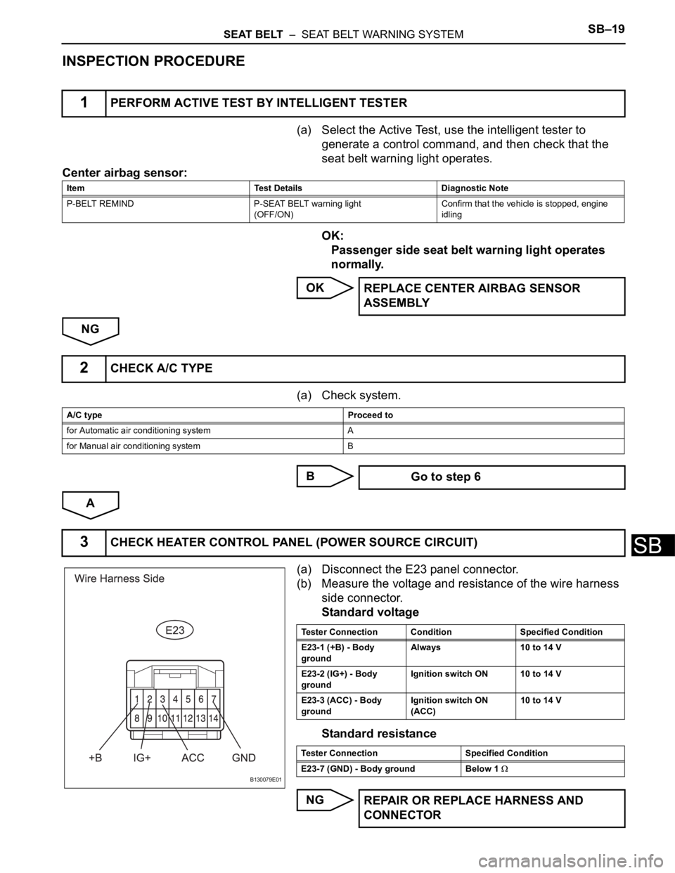
(a) Select the Active Test, use the intelligent tester to
generate a control command, and then check that the
seat belt warning light operates.
Center airbag sensor:
OK:
Passenger side seat belt warning light operates
normally.
OK
NG
(a) Check system.
B
A
(a) Disconnect the E23 panel connector.
(b) Measure the voltage and resistance of the wire harness
side connector.
Standard voltage
Standard resistance
NG
1PERFORM ACTIVE TEST BY INTELLIGENT TESTER
Item Test Details Diagnostic Note
P-BELT REMIND P-SEAT BELT warning light
(OFF/ON)Confirm that the vehicle is stopped, engine
idling
REPLACE CENTER AIRBAG SENSOR
ASSEMBLY
2CHECK A/C TYPE
A/C type Proceed to
for Automatic air conditioning system A
for Manual air conditioning system B
Go to step 6
3CHECK HEATER CONTROL PANEL (POWER SOURCE CIRCUIT)
B130079E01
Tester Connection Condition Specified Condition
E23-1 (+B) - Body
groundAlways 10 to 14 V
E23-2 (IG+) - Body
groundIgnition switch ON 10 to 14 V
E23-3 (ACC) - Body
groundIgnition switch ON
(ACC)10 to 14 V
Tester Connection Specified Condition
E23-7 (GND) - Body ground Below 1
REPAIR OR REPLACE HARNESS AND
CONNECTOR
Page 1758 of 2000
SB–20SEAT BELT – SEAT BELT WARNING SYSTEM
SB
OK
(a) Disconnect the E23 panel connector.
(b) Disconnect the E19 meter connector.
(c) Measure the resistance of the wire harness side
connectors.
Standard resistance
NG
OK
(a) Remove the heater control panel.
4CHECK WIRE HARNESS (HEATER CONTROL PANEL - COMBINATION METER
ASSEMBLY)
B130080E01
Tester Connection Specified Condition
E19-1 (PBLT) - E23-4 (PBEW) Below 1
REPAIR OR REPLACE HARNESS AND
CONNECTOR
5INSPECT HEATER CONTROL PANEL
Page 1759 of 2000

SEAT BELT – SEAT BELT WARNING SYSTEMSB–21
SB
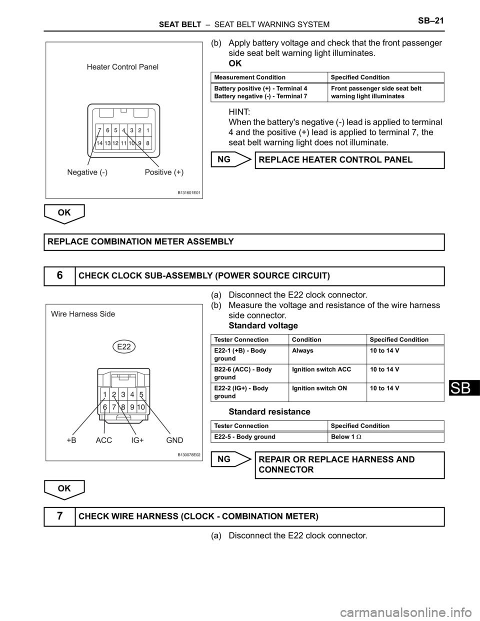
(b) Apply battery voltage and check that the front passenger
side seat belt warning light illuminates.
OK
HINT:
When the battery's negative (-) lead is applied to terminal
4 and the positive (+) lead is applied to terminal 7, the
seat belt warning light does not illuminate.
NG
OK
(a) Disconnect the E22 clock connector.
(b) Measure the voltage and resistance of the wire harness
side connector.
Standard voltage
Standard resistance
NG
OK
(a) Disconnect the E22 clock connector.
B131601E01
Measurement Condition Specified Condition
Battery positive (+) - Terminal 4
Battery negative (-) - Terminal 7Front passenger side seat belt
warning light illuminates
REPLACE HEATER CONTROL PANEL
REPLACE COMBINATION METER ASSEMBLY
6CHECK CLOCK SUB-ASSEMBLY (POWER SOURCE CIRCUIT)
B130078E02
Tester Connection Condition Specified Condition
E22-1 (+B) - Body
groundAlways 10 to 14 V
B22-6 (ACC) - Body
groundIgnition switch ACC 10 to 14 V
E22-2 (IG+) - Body
groundIgnition switch ON 10 to 14 V
Tester Connection Specified Condition
E22-5 - Body ground Below 1
REPAIR OR REPLACE HARNESS AND
CONNECTOR
7CHECK WIRE HARNESS (CLOCK - COMBINATION METER)
Page 1760 of 2000
SB–22SEAT BELT – SEAT BELT WARNING SYSTEM
SB
(b) Disconnect the E19 meter connector.
(c) Measure the resistance of the wire harness side
connectors.
Standard resistance
NG
OK
(a) Remove the clock.
(b) Apply battery voltage and check that the front passenger
side seat belt warning light illuminates.
OK
HINT:
When the battery's negative (-) lead is applied to terminal
3 and the positive (+) lead is applied to terminal 5, the
seat belt warning light does not illuminate.
NG
OK
B130081E01
Tester Connection Specified Condition
E22-3 (PBEW) - E19-1 (PBLT) Below 1
REPAIR OR REPLACE HARNESS AND
CONNECTOR
8INSPECT CLOCK SUB-ASSEMBLY
B131600E01
Measurement Condition Specified Condition
Battery positive (+) - Terminal 3
Battery negative (-) - Terminal 5Front passenger side seat belt
warning light illuminates
REPLACE CLOCK SUB-ASSEMBLY
REPLACE COMBINATION METER ASSEMBLY
Page 1786 of 2000

ENGINE IMMOBILISER – ENGINE IMMOBILISER SYSTEMEI–15
EI
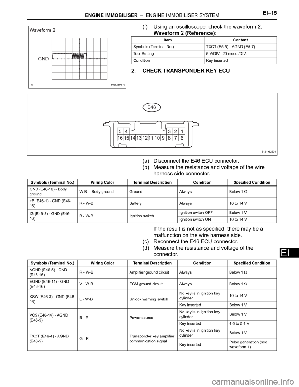
(f) Using an oscilloscope, check the waveform 2.
Waveform 2 (Reference):
2. CHECK TRANSPONDER KEY ECU
(a) Disconnect the E46 ECU connector.
(b) Measure the resistance and voltage of the wire
harness side connector.
If the result is not as specified, there may be a
malfunction on the wire harness side.
(c) Reconnect the E46 ECU connector.
(d) Measure the resistance and voltage of the
connector.
B069239E10
Item Content
Symbols (Terminal No.) TXCT (E5-5) - AGND (E5-7)
Tool Setting 5 V/DIV., 20 msec./DIV.
Condition Key inserted
B121962E04
Symbols (Terminal No.) Wiring Color Terminal Description ConditionSpecified Condition
GND (E46-16) - Body
groundW-B - Body ground Ground Always Below 1
+B (E46-1) - GND (E46-
16)R - W-B Battery Always 10 to 14 V
IG (E46-2) - GND (E46-
16)B - W-B Ignition switchIgnition switch OFF Below 1 V
Ignition switch ON 10 to 14 V
Symbols (Terminal No.) Wiring Color Terminal Description ConditionSpecified Condition
AGND (E46-5) - GND
(E46-16)R - W-B Amplifier ground circuit Always Below 1
EGND (E46-11) - GND
(E46-16)V - W-B ECM ground circuit Always Below 1
KSW (E46-3) - GND (E46-
16)L - W-B Unlock warning switchNo key is in ignition key
cylinder10 to 14 V
Key inserted Below 1 V
VC5 (E46-14) - AGND
(E46-5)B - R Power sourceNo key is in ignition key
cylinderBelow 1 V
Key inserted 4.6 to 5.4 V
TXCT (E46-4) - AGND
(E46-5)G - RTransponder key amplifier
communication signalNo key is in ignition key
cylinderBelow 1 V
Key insertedPulse generation (see
waveform 1)
Page 1792 of 2000

ENGINE IMMOBILISER – ENGINE IMMOBILISER SYSTEMEI–21
EI
DATA LIST / ACTIVE TEST
1. READ DATA LIST
HINT:
Using the intelligent tester's DATA LIST allows switch,
sensor, actuator and other item values to be read without
removing any parts. Reading the DATA LIST early in
troubleshooting is one way to save time.
(a) Connect the intelligent tester (with CAN VIM) to the
DLC3.
(b) Turn the ignition switch ON and turn the tester ON.
(c) Select the following menu items: DIAGNOSIS /
OBD/MOBD / IMMOBILISER / DATA LIST.
(d) Check the results by referring to the table below.
Transponder key ECU:
ItemMeasurement Item / Display
(Range)Normal Condition Diagnostic Note
KEY SWUnlock warning switch signal /
ON or OFFON: Key is in ignition key cylinder
OFF: No key is in ignition key
cylinder-
IG SW Ignition switch signal / ON or OFFON: Ignition switch ON (IG or
ACC)
OFF: Ignition switch OFF-
IMMOBILISERImmobiliser system status / SET
or UNSETSET: No key is in ignition key
cylinder
UNSET: Key is in ignition key
cylinder-
PERMIT (START)Engine starting control / OK or
NGOK: Engine start is permitted
NG: Engine start is not permitted-
RESPONSETransponder chip data / NG or
OKNG: Data error
OK: Data OK-
FRAME ERRORTransponder chip data / NG or
OKNG: Data error
OK: Data OK-
SERIAL NUMBERTransponder chip data / NG or
OKNG: Data error
OK: Data OK-
ENCRYPT CODETransponder chip data / NG or
OKNG: Data error
OK: Data OK-
STATUSTransponder chip data / NG or
OKNG: Data error
OK: Data OK-
BCCTransponder chip signal / NG or
OKNG: Incorrect data sent
OK: Correct data sent-
SUB KEYSub-key code signal / MATCH or
NOMATCHMATCH: Registered sub-key
code is sent
NOMATCH: Unmatched sub-key
code is sent-
MASTER KEYMaster key code signal / MATCH
or NOMATCHMATCH: Registered master key
code is sent
NOMATCH: Unmatched master
key code is sent-
REGIST SUB CODENumber of registered sub-keys /
min.: 0, max.: 15Number of registered sub-keys -
REGIST MAS CODENumber of registered master
keys / min.: 0, max.: 15Number of registered master
keys-
REG CODE SPACEKey registration code memory
space full / NOTFULL or FULLNOTFULL: Possible to register
more key codes
FULL: Cannot register any more
key codes-
Page 1794 of 2000
ENGINE IMMOBILISER – ENGINE IMMOBILISER SYSTEMEI–23
EI
DIAGNOSTIC TROUBLE CODE CHART
Transponder key ECU:
ECM:
DTC No. Detection Item Trouble Area See page
B2780Push Switch / Key Unlock
Warning Switch Malfunction- Transponder key ECU
- Unlock warning switch
- Wire harnessEI-21
B2784Antenna Coil Open / Short - Transponder key ECU
- Transponder key amplifier
- Wire harnessEI-24
B2793 Transponder Chip Malfunction KeyEI-26
B2794 Unmatched Encryption Code KeyEI-27
B2795 Unmatched Key Code KeyEI-28
B2796No Communication in Immobiliser
System- Transponder key ECU
- Key
- Wire harness
- Transponder key amplifierEI-29
B2797Communication Malfunction No. 1 - Key
- Wire harness
- Transponder key ECU
- Transponder key amplifierEI-32
B2798 Communication Malfunction No. 2 KeyEI-29
DTC No. Detection Item Trouble Area See page
B2799Engine Immobiliser System - Wire harness
- Transponder key ECU
- ECMEI-36