Page 1671 of 2000
AIR CONDITIONING – AMBIENT TEMPERATURE SENSOR (for Automatic Air Conditioning
System)AC–233
AC
INSTALLATION
1. INSTALL AMBIENT TEMPERATURE SENSOR
(a) Connect the connector, and then push in the sensor.
2. INSTALL FRONT BUMPER COVER
(a) Install the front bumper cover (see page ET-10).
3. CONNECT CABLE TO NEGATIVE BATTERY
TERMINAL
4. CHECK SRS WARNING LIGHT
(a) Check SRS warning light (see page RS-37).
Page 1672 of 2000
AIR CONDITIONING – SOLAR SENSOR (for Automatic Air Conditioning System)AC–237
AC
INSTALLATION
1. INSTALL SOLAR SENSOR
(a) Connect the connector, and then push in the solar
sensor.
2. CONNECT CABLE TO NEGATIVE BATTERY
TERMINAL
3. CHECK SRS WARNING LIGHT
(a) Check the SRS warning light (see page RS-37).
Page 1676 of 2000

SUPPLEMENTAL RESTRAINT SYSTEM – AIRBAG SYSTEMRS–27
RS
• The center airbag sensor receives signals
from the deceleration sensor and the
electronic safing sensor built into the center
airbag sensor and the rear airbag sensor, and
determines whether or not the side airbag
and curtain shield airbag should be activated,
and diagnoses system malfunctions.
• The center airbag sensor sends the airbag
deployment signal to ECM through the CAN
to operate the fuel pump control.
(2) Deceleration sensor and ignition control circuit
• The deceleration sensor is built into the
center airbag sensor.
• The ignition control circuit performs
calculations based on the signal output from
the deceleration sensors of the center airbag
sensor and front airbag sensor. If the
calculated values are greater than the
specified values, it activates the deployment
operation.
(3) Safing sensor
The safing sensor is built into the center airbag
sensor. During a frontal collision, the sensor
turns on and outputs an ON signal to the center
airbag sensor if a deceleration rate greater than
the specified value is applied to the safing
sensor.
(4) Electronic safing sensor
The electronic safing sensor is built into the
center airbag sensor. During a side collision, the
sensor turns on and outputs an ON signal to the
center airbag sensor if a deceleration rate
greater than the specified value is applied to the
electronic safing sensor.
(5) Back-up power source
The back-up power source consists of a power
supply capacitor and a DC-DC converter. When
the power system does not function during a
collision, the power supply capacitor discharges
and supplies electric power to the system. The
DC-DC converter operates as a boosting
transformer when the battery voltage falls below
a predetermined level.
(6) Diagnostic circuit
This circuit constantly diagnoses system
malfunctions. When a malfunction is detected, it
lights up the SRS warning light on the telltale
light to inform the driver.
(7) Memory circuit
When a malfunction is detected in the diagnostic
circuit, it is coded and stored in the memory
circuit.
Page 1677 of 2000

RS–28SUPPLEMENTAL RESTRAINT SYSTEM – AIRBAG SYSTEM
RS
(e) SRS WARNING LIGHT
(1) The SRS warning light is located on the telltale
light. It comes on to inform the driver of system
trouble when a malfunction is detected in the
self-diagnosis of the center airbag sensor. Under
normal operating conditions when the ignition
switch is turned on, it comes on for
approximately 6 seconds and then goes off.
3. DEPLOYMENT CONDITION
When the vehicle collides and the shock is greater than
the specified value, the SRS is activated automatically.
The center airbag sensor includes the safing sensor and
deceleration sensor. The safing sensor was designed to
be turned on at a smaller deceleration rate than the
deceleration sensor.
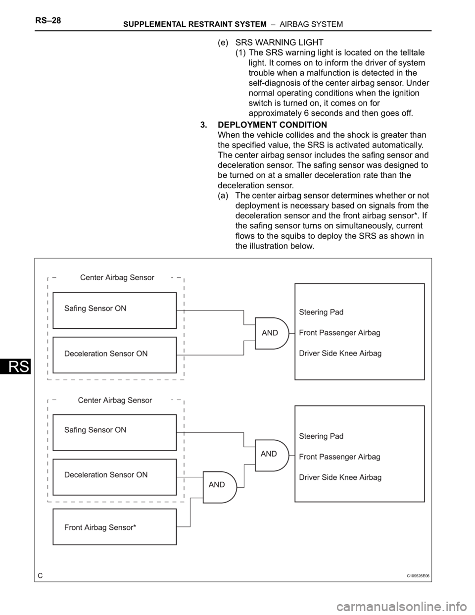
(a) The center airbag sensor determines whether or not
deployment is necessary based on signals from the
deceleration sensor and the front airbag sensor*. If
the safing sensor turns on simultaneously, current
flows to the squibs to deploy the SRS as shown in
the illustration below.
C109526E06
Page 1682 of 2000
SUPPLEMENTAL RESTRAINT SYSTEM – AIRBAG SYSTEMRS–33
RS
NEXT
(a) Check the DTC.
Result
B
A
NEXT
NEXT
NEXT
NEXT
(a) Check the DTC.
Result
B
5WARNING LIGHT CHECK*
6CHECK FOR DTC (Present and Past DTCs)
Result Proceed to
DTC is not output A
DTC is output B
PROBLEM SYMPTOMS TABLE
7DTC CHART
8CIRCUIT INSPECTION
9REPAIR*
10CLEAR DTC (Present and Past DTCs)*
11CHECK FOR DTC (Present and Past DTCs)
Result Proceed to
DTC is not output A
DTC is output B
Go to step 6
Page 1684 of 2000

SUPPLEMENTAL RESTRAINT SYSTEM – AIRBAG SYSTEMRS–35
RS
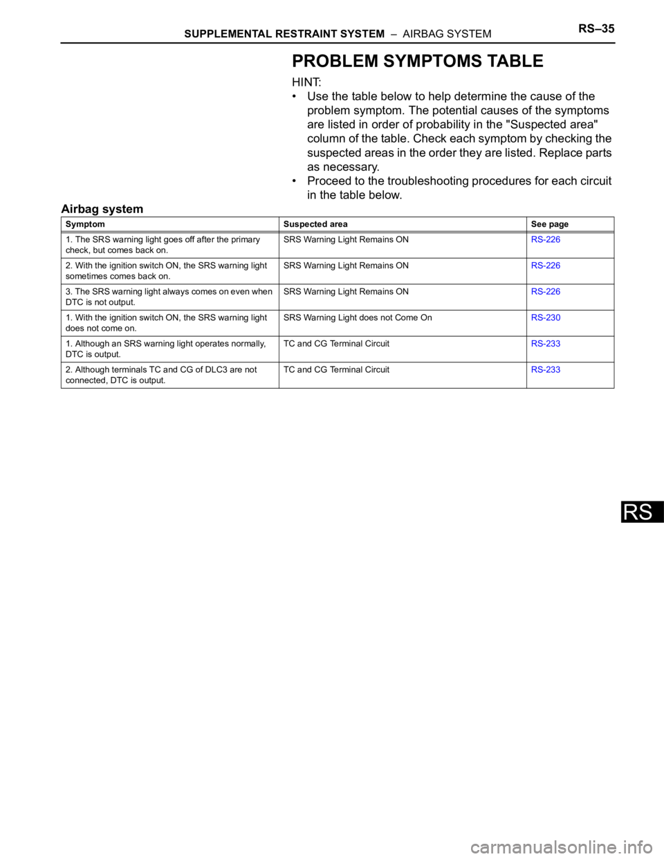
PROBLEM SYMPTOMS TABLE
HINT:
• Use the table below to help determine the cause of the
problem symptom. The potential causes of the symptoms
are listed in order of probability in the "Suspected area"
column of the table. Check each symptom by checking the
suspected areas in the order they are listed. Replace parts
as necessary.
• Proceed to the troubleshooting procedures for each circuit
in the table below.
Airbag system
Symptom Suspected area See page
1. The SRS warning light goes off after the primary
check, but comes back on.SRS Warning Light Remains ONRS-226
2. With the ignition switch ON, the SRS warning light
sometimes comes back on.SRS Warning Light Remains ONRS-226
3. The SRS warning light always comes on even when
DTC is not output.SRS Warning Light Remains ONRS-226
1. With the ignition switch ON, the SRS warning light
does not come on.SRS Warning Light does not Come OnRS-230
1. Although an SRS warning light operates normally,
DTC is output.TC and CG Terminal CircuitRS-233
2. Although terminals TC and CG of DLC3 are not
connected, DTC is output.TC and CG Terminal CircuitRS-233
Page 1686 of 2000

SUPPLEMENTAL RESTRAINT SYSTEM – AIRBAG SYSTEMRS–37
RS
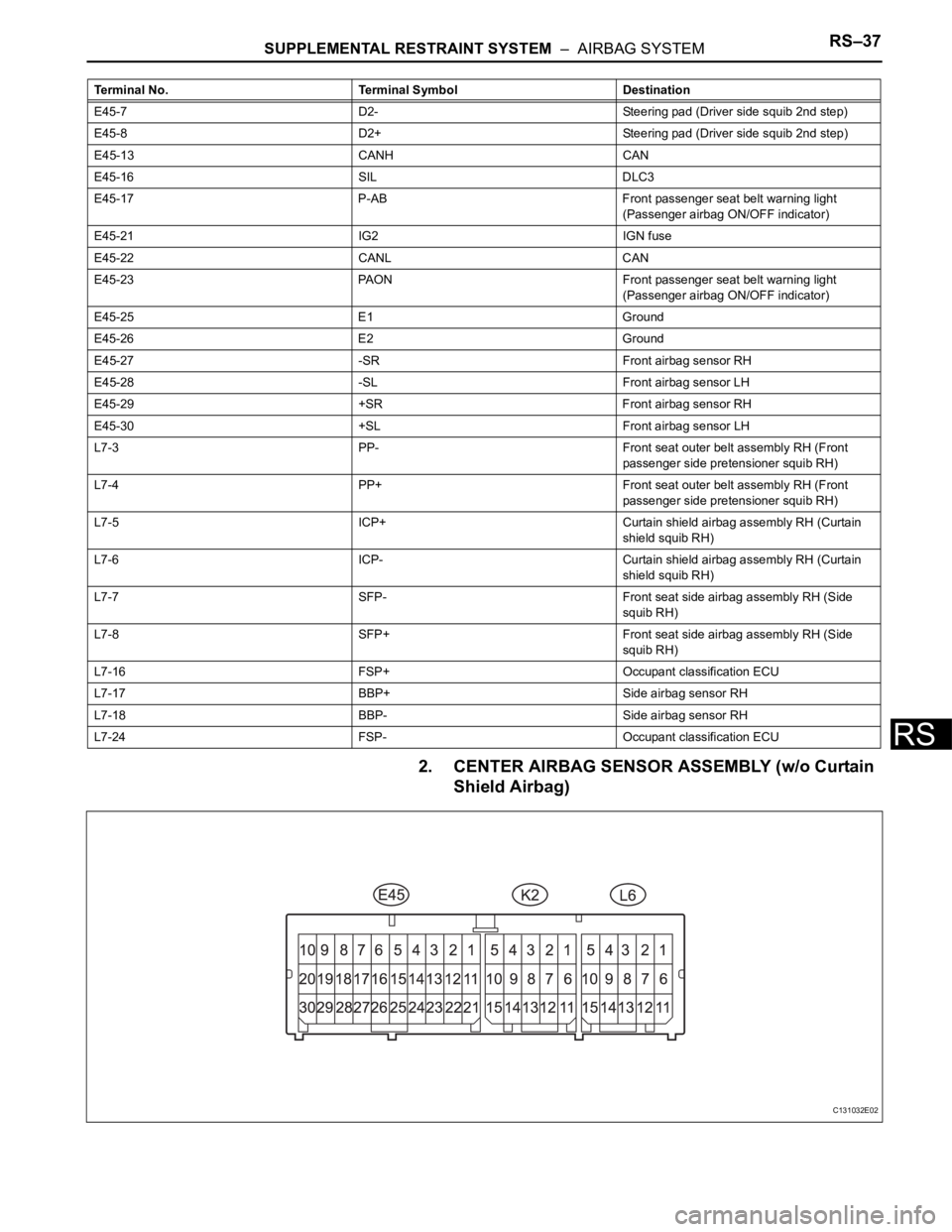
2. CENTER AIRBAG SENSOR ASSEMBLY (w/o Curtain
Shield Airbag)
E45-7 D2- Steering pad (Driver side squib 2nd step)
E45-8 D2+ Steering pad (Driver side squib 2nd step)
E45-13 CANH CAN
E45-16 SIL DLC3
E45-17 P-AB Front passenger seat belt warning light
(Passenger airbag ON/OFF indicator)
E45-21 IG2 IGN fuse
E45-22 CANL CAN
E45-23 PAON Front passenger seat belt warning light
(Passenger airbag ON/OFF indicator)
E45-25 E1 Ground
E45-26 E2 Ground
E45-27 -SR Front airbag sensor RH
E45-28 -SL Front airbag sensor LH
E45-29 +SR Front airbag sensor RH
E45-30 +SL Front airbag sensor LH
L7-3 PP- Front seat outer belt assembly RH (Front
passenger side pretensioner squib RH)
L7-4 PP+ Front seat outer belt assembly RH (Front
passenger side pretensioner squib RH)
L7-5 ICP+ Curtain shield airbag assembly RH (Curtain
shield squib RH)
L7-6 ICP- Curtain shield airbag assembly RH (Curtain
shield squib RH)
L7-7 SFP- Front seat side airbag assembly RH (Side
squib RH)
L7-8 SFP+ Front seat side airbag assembly RH (Side
squib RH)
L7-16 FSP+ Occupant classification ECU
L7-17 BBP+ Side airbag sensor RH
L7-18 BBP- Side airbag sensor RH
L7-24 FSP- Occupant classification ECU Terminal No. Terminal Symbol Destination
C131032E02
Page 1687 of 2000

RS–38SUPPLEMENTAL RESTRAINT SYSTEM – AIRBAG SYSTEM
RS
Terminal No. Terminal Symbol Destination
E45-1 P2+ Front passenger airbag (Front passenger side
squib 2nd step)
E45-2P2- Front passenger airbag (Front passenger side
squib 2nd step)
E45-3P- Front passenger airbag (Front passenger side
squib)
E45-4 P+ Front passenger airbag (Front passenger side
squib)
E45-5 D+ Steering pad (Driver side squib)
E45-6 D- Steering pad (Driver side squib)
E45-7 D2- Steering pad (Driver side squib 2nd step)
E45-8 D2+ Steering pad (Driver side squib 2nd step)
E45-13 CANH CAN
E45-16 SIL DLC3
E45-17 P-AB Front passenger seat belt warning light
(Passenger airbag ON/OFF indicator)
E45-21 IG2 IGN fuse
E45-22 CANL CAN
E45-23 PAON Front passenger seat belt warning light
(Passenger airbag ON/OFF indicator)
E45-25 E1 Ground
E45-26 E2 Ground
E45-27 -SR Front airbag sensor RH
E45-28 -SL Front airbag sensor LH
E45-29 +SR Front airbag sensor RH
E45-30 +SL Front airbag sensor LH
K2-1 PD- Front seat outer belt assembly LH (Driver side
pretensioner squib)
K2-2 PD+ Front seat outer belt assembly LH (Driver side
pretensioner squib)
K2-11 DBE+ Front seat inner belt assembly LH
K2-12 DBE- Front seat inner belt assembly LH
K2-13 DSP- Seat position sensor
K2-14 DSP+ Seat position sensor
L6-4 PP+ Front seat outer belt assembly RH (Front
passenger side pretensioner squib RH)
L6-5 PP- Front seat outer belt assembly RH (Front
passenger side pretensioner squib RH)
L6-12 FSP+ Occupant classification ECU
L6-13 FSP- Occupant classification ECU