2006 LAND ROVER FRELANDER 2 brake
[x] Cancel search: brakePage 195 of 3229
Publi s hed: 11-May-2011
Suspension System - General Information - Suspension System
Diagnosi s and Tes ti ng
Principles of Operation
For a detail ed descripti on of the sus pens i on sys t em, refer t o t he rel evant Des cript ion and Operat ion s ecti on in theworks hop manual . REFER to:
Front Sus pensi on (204-01 Front Sus pensi on, Des cri pti on and Operati on),Rear Sus pens ion (204-02 Rear Suspens ion, Descri pti on and Operat ion),Ride and Handli ng Opti mizati on (204-06 Ride and Handli ng Opti mizat ion, Descri pti on and Operat ion).
Inspection and Verification
1. Verify t he cus t omer concern.1.
2. Vis ually ins pect for obvious s igns of damage.2.
Visual InspectionMechanical
Damaged t iresW heel bearing(s)Loose or damaged front or rear s uspens ion component sLoose, damaged or mis s ing s us pens ion fas tener(s )Incorrect spring(s ) i ns t alledDamaged or s aggi ng spring(s )Damaged or leaking s hock abs orber(s )Damaged or leaking s t rut (s )W orn or damaged s us pensi on bushi ng(s )Loose, worn or damaged s t eering sys tem componentsDamaged axle component s
3. If an obvious cause for an obs erved or report ed concern is found, correct t he caus e (if pos s ible) beforeproceeding t o t he next s t ep.3.
4. If t he caus e is not vis ually evi dent , verify t he sympt om and refer t o t he Sympt om Chart.4.
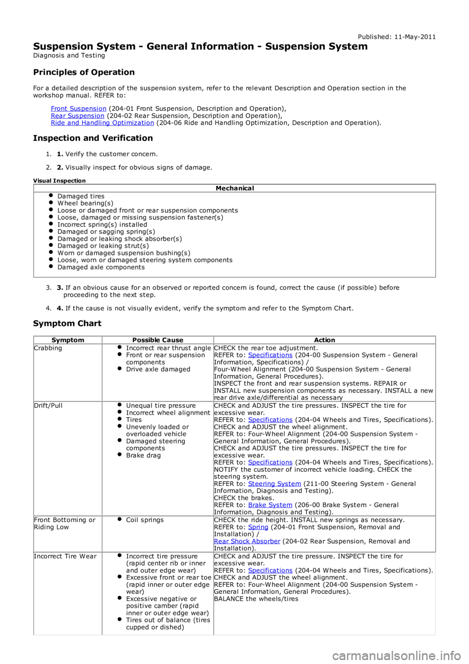
Symptom Chart
SymptomPossible CauseAction
CrabbingIncorrect rear thrus t angleFront or rear s uspens ioncomponent sDrive axle damaged
CHECK t he rear toe adjust ment.REFER to: Speci fi cat ions (204-00 Suspens ion Syst em - GeneralInformat ion, Specificati ons) /Four-W heel Al ignment (204-00 Sus pens i on Sys t em - GeneralInformat ion, General Procedures ).INSPECT t he front and rear s us pensi on s yst ems . REPAIR orINSTALL new s us pens ion component s as neces s ary. INSTALL a newrear dri ve axl e/di fferenti al as necess ary
Drift/Pul lUnequal t ire pres s ureIncorrect wheel ali gnmentTiresUnevenl y loaded oroverloaded vehi cleDamaged s teeri ngcomponent sBrake drag
CHECK and ADJUST the t ire pres s ures . INSPECT t he ti re forexces si ve wear.REFER to: Speci fi cat ions (204-04 W heels and Ti res , Specificati ons ).CHECK and ADJUST the wheel ali gnment .REFER to: Four-W heel Al ignment (204-00 Sus pensi on Syst em -General Informat ion, General Procedures ).CHECK and ADJUST the t ire pres s ures . INSPECT t he ti re forexces si ve wear.REFER to: Speci fi cat ions (204-04 W heels and Ti res , Specificati ons ).NOTIFY the cus tomer of incorrect vehicle l oadi ng. CHECK thes teeri ng s ys t em.REFER to: St eering Sys tem (211-00 St eeri ng Sys t em - GeneralInformat ion, Diagnosi s and Test ing).CHECK t he brakes .REFER to: Brake Sys tem (206-00 Brake Syst em - GeneralInformat ion, Diagnosi s and Test ing).Front Bott omi ng orRidi ng LowCoil s pri ngsCHECK t he ri de hei ght. INSTALL new springs as neces s ary.REFER to: Spri ng (204-01 Front Sus pensi on, Removal andIns t al lat ion) /Rear Shock Absorber (204-02 Rear Sus pensi on, Removal andIns t al lat ion).
Incorrect Ti re W earIncorrect ti re press ure(rapid center rib or i nnerand outer edge wear)Exces s ive front or rear toe(rapid inner or out er edgewear)Exces s ive negat ive orposi ti ve camber (rapi dinner or out er edge wear)Tires out of bal ance (ti rescupped or dis hed)
CHECK and ADJUST the t ire pres s ure. INSPECT t he t ire forexces si ve wear.REFER to: Speci fi cat ions (204-04 W heels and Ti res , Specificati ons ).CHECK and ADJUST the wheel ali gnment .REFER to: Four-W heel Al ignment (204-00 Sus pensi on Syst em -General Informat ion, General Procedures ).BALANCE the wheels /ti res
Page 196 of 3229
Publi s hed: 11-May-2011
Suspension System - General Information - Four-Wheel Alignment
General Procedures
Check the geomet ry s peci fi cat ions .
Refer t o: Specificati ons (204-00 Sus pens i on Sys t em - GeneralInformat ion, Speci fi cat ions ).
1.
Check the t ie rod ends , sus pens i on joi nt s , wheel beari ngs andwheels and t ires for damage, wear and free pl ay.2.
Check and adjust t ire pres s ures .3.
Pos it ion t he vehi cl e on a cal ibrat ed, l evel , vehicl e li ft .4.
Releas e t he vehi cl e parking brake.5.
Us ing onl y four wheel al ignment equi pment approved by Land Rover,check and adjus t t he wheel al ignment.6.
7. W ARNING: Make sure t o s upport the vehicle wit h axles tands .
Rais e and s upport t he vehi cl e.
7.
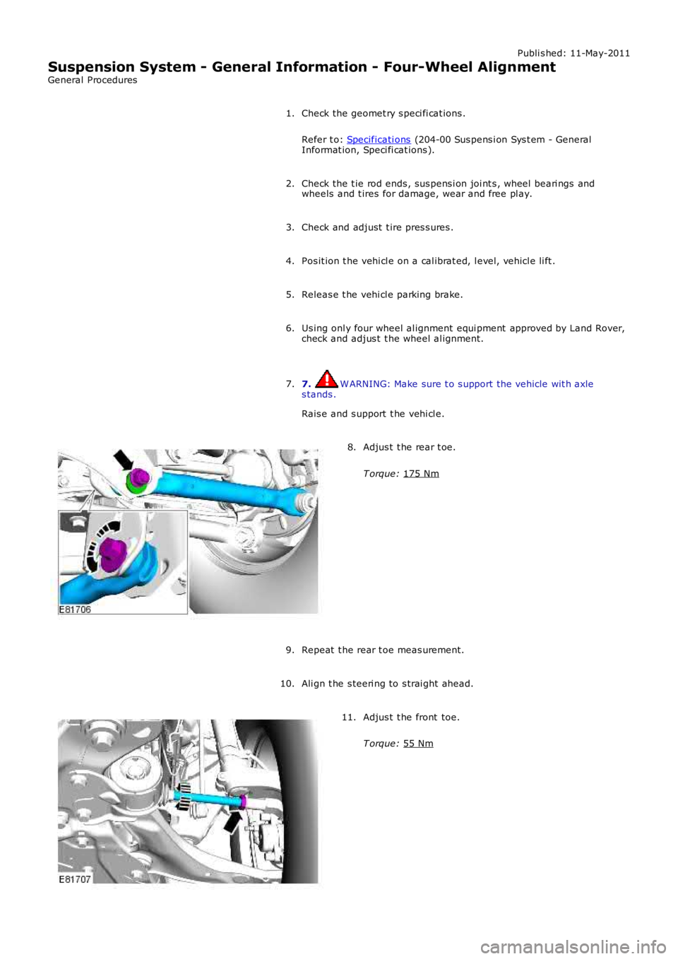
Adjus t t he rear t oe.
T orque: 175 Nm
8.
Repeat t he rear t oe meas urement.9.
Ali gn t he s teeri ng to s trai ght ahead.10.
Adjus t t he front toe.
T orque: 55 Nm
11.
Page 200 of 3229
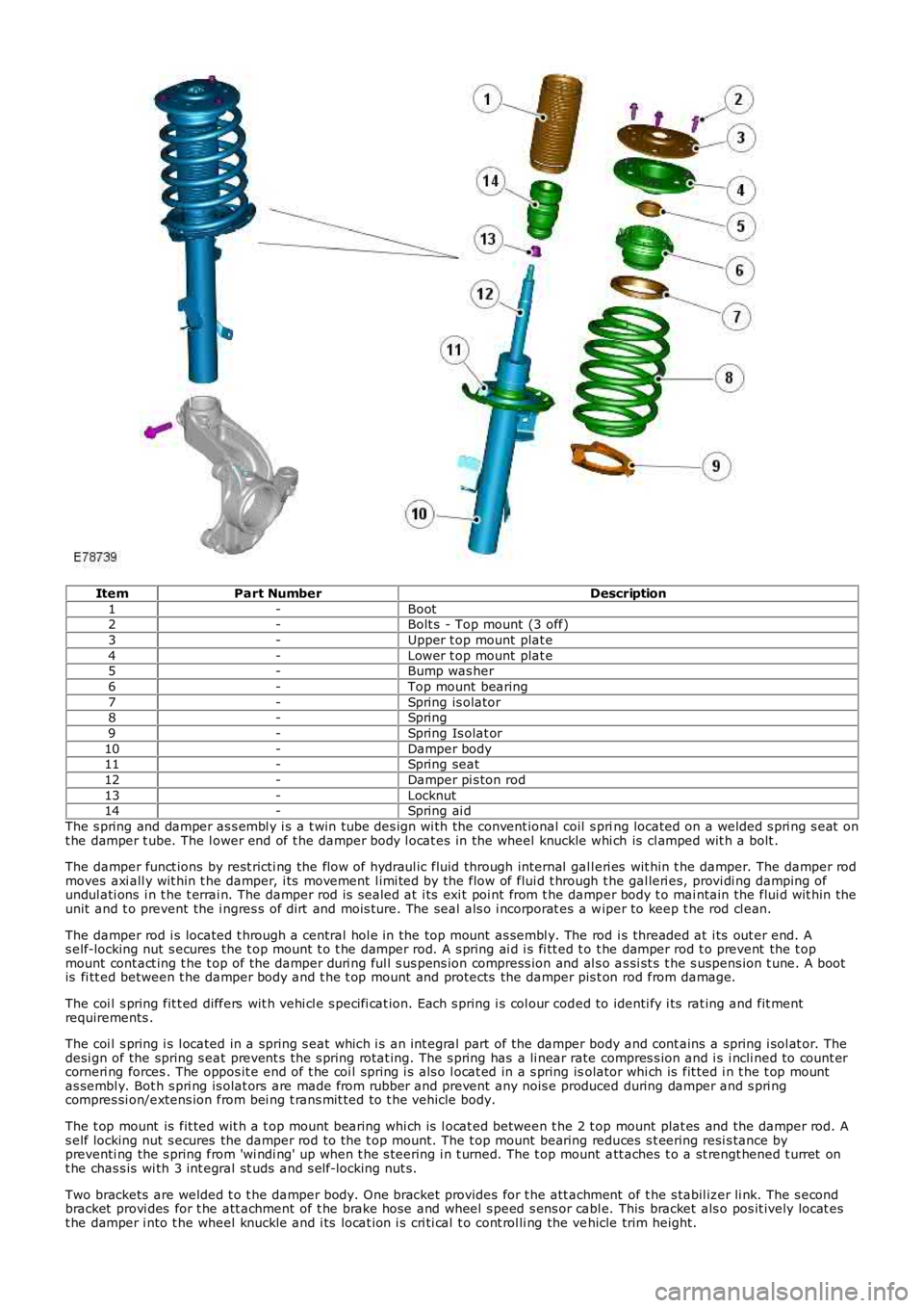
ItemPart NumberDescription
1-Boot2-Bolt s - Top mount (3 off)
3-Upper t op mount plat e
4-Lower t op mount plat e5-Bump was her
6-Top mount bearing
7-Spring is olator8-Spring
9-Spring Is olat or
10-Damper body11-Spring seat
12-Damper pi s ton rod
13-Locknut14-Spring ai d
The s pring and damper as s embl y i s a t win tube des ign wi th the convent ional coil s pring located on a welded s pri ng s eat ont he damper t ube. The l ower end of t he damper body l ocat es in the wheel knuckle whi ch is cl amped wit h a bolt .
The damper funct ions by rest ricti ng the flow of hydraul ic fluid through internal gall eri es wit hin t he damper. The damper rodmoves axi all y wit hin t he damper, i ts movement l imi ted by the flow of flui d t hrough the gal leri es, provi di ng damping ofundul ati ons i n t he t errai n. The damper rod is s ealed at i ts exi t poi nt from t he damper body t o mai ntain the flui d wit hin theunit and t o prevent the i ngres s of dirt and mois ture. The seal als o i ncorporat es a wiper to keep t he rod cl ean.
The damper rod i s located t hrough a central hol e in the top mount as sembl y. The rod i s threaded at i ts out er end. As elf-locking nut s ecures the t op mount t o t he damper rod. A s pring ai d i s fi tt ed t o t he damper rod t o prevent the t opmount cont act ing t he t op of the damper duri ng ful l s us pens ion compress ion and al s o as si st s t he s uspens ion t une. A bootis fi tt ed between t he damper body and t he t op mount and protects the damper pis t on rod from damage.
The coi l s pring fit t ed differs wit h vehi cl e s peci fi cat ion. Each s pring i s col our coded to identi fy i ts rat ing and fit mentrequirements .
The coi l s pring i s l ocated in a spring s eat which i s an int egral part of the damper body and cont ains a spring i sol at or. Thedesi gn of the spring s eat prevent s t he s pring rotat ing. The s pring has a li near rate compres s ion and i s i ncli ned to count ercorneri ng forces . The oppos it e end of t he coi l spring i s als o l ocat ed in a s pring isolator whi ch is fit ted i n t he t op mountas sembl y. Bot h s pri ng is olat ors are made from rubber and prevent any nois e produced during damper and s pri ngcompres si on/extens ion from bei ng t rans mit ted to t he vehicle body.
The t op mount is fit ted wit h a t op mount bearing whi ch is l ocat ed between t he 2 t op mount plat es and the damper rod. As elf locking nut s ecures the damper rod to the t op mount. The t op mount bearing reduces s t eering resi s tance bypreventi ng the s pring from 'wi ndi ng' up when t he s teering i n t urned. The t op mount att aches t o a st rengt hened t urret ont he chas s is wi th 3 int egral st uds and s elf-locking nut s.
Two brackets are welded t o t he damper body. One bracket provides for t he att achment of t he s tabil izer li nk. The s econdbracket provi des for t he att achment of t he brake hose and wheel s peed s ens or cabl e. This bracket als o pos it ively locat est he damper i nto t he wheel knuckle and i ts locat ion i s cri ti cal t o cont rol li ng the vehicle trim height.
Page 202 of 3229
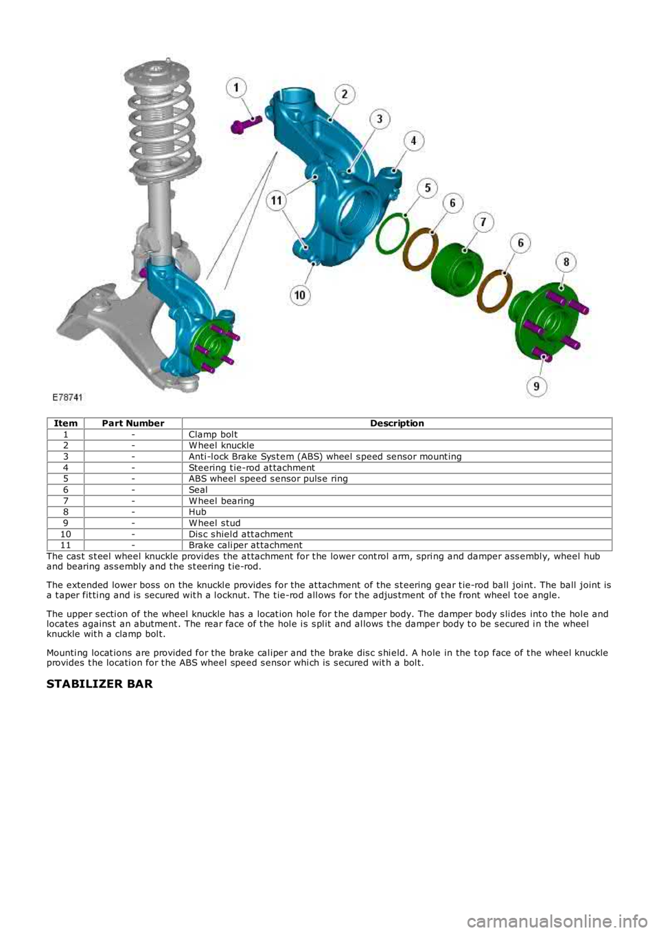
ItemPart NumberDescription
1-Clamp bol t2-W heel knuckle
3-Anti -l ock Brake Sys t em (ABS) wheel s peed sens or mount ing
4-Steering t ie-rod at tachment5-ABS wheel speed s ensor puls e ring
6-Seal
7-W heel bearing8-Hub
9-W heel s tud
10-Dis c s hiel d att achment11-Brake cali per at tachment
The cas t s t eel wheel knuckle provi des the at tachment for t he lower cont rol arm, spring and damper ass embl y, wheel huband bearing as s embly and t he s t eering t ie-rod.
The extended lower boss on the knuckl e provides for the at tachment of the s t eering gear t ie-rod ball joi nt. The ball joint isa t aper fit ti ng and is secured wit h a l ocknut. The t ie-rod all ows for t he adjus tment of t he front wheel t oe angle.
The upper s ecti on of the wheel knuckle has a locat ion hol e for t he damper body. The damper body s li des int o the hol e andlocates agains t an abutment . The rear face of t he hol e i s s pl it and al lows t he damper body t o be s ecured i n the wheelknuckle wit h a clamp bol t.
Mounti ng locat ions are provided for the brake cal iper and the brake dis c s hi eld. A hole in the t op face of t he wheel knuckl eprovides t he locati on for t he ABS wheel speed s ensor whi ch is s ecured wit h a bol t.
STABILIZER BAR
Page 210 of 3229
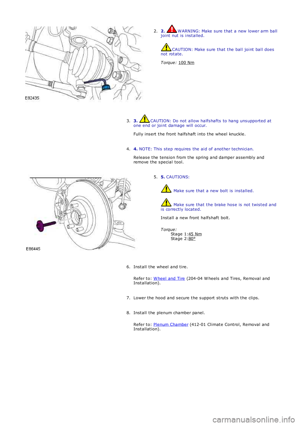
Stage 1:Stage 2:
2. W ARNING: Make sure t hat a new lower arm balljoi nt nut is i ns t alled.
CAUTION: Make s ure that t he bal l joi nt bal l doesnot rot ate.
T orque: 100 Nm
2.
3. CAUTION: Do not all ow halfs hafts to hang uns upported atone end or joi nt damage will occur.
Full y ins ert t he front hal fs haft i nto t he wheel knuckle.
3.
4. NOTE: Thi s s tep requires the ai d of anot her techni ci an.
Releas e t he tens ion from t he spring and damper as sembl y andremove the s peci al tool.
4.
5. CAUTIONS:
Make s ure that a new bol t is ins tall ed.
Make s ure that t he brake hos e is not t wis t ed andi s correctl y located.
Inst all a new front halfs haft bolt .
T orque:45 Nm80°
5.
Inst all t he wheel and t ire.
Refer t o: W heel and Ti re (204-04 W heel s and Tires, Removal andInst all at ion).
6.
Lower the hood and s ecure t he s upport st rut s wi th t he cli ps.7.
Inst all t he plenum chamber panel.
Refer t o: Plenum Chamber (412-01 Cl imat e Control, Removal andInst all at ion).
8.
Page 220 of 3229
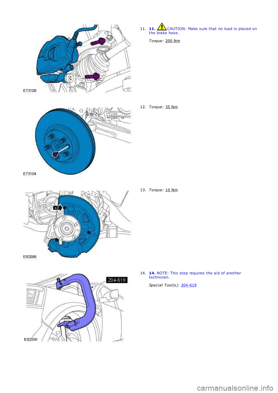
11. CAUTION: Make s ure t hat no load i s placed on
t he brake hos e.
T orque: 200 Nm 11.
T orque:
35 Nm 12.
T orque:
10 Nm 13.
14.
NOTE: Thi s s tep requires the ai d of anot her
t echnician.
Speci al Tool (s ): 204-619 14.
Page 222 of 3229
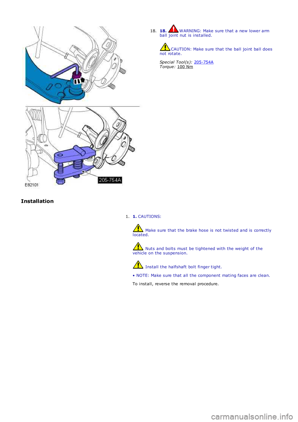
18. W ARNING: Make sure t hat a new lower arm
ball joi nt nut is i ns t alled. CAUTION: Make s ure that t he bal l joi nt bal l does
not rot ate.
Speci al Tool (s ): 205-754A T orque:
100 Nm 18.
Installation 1. CAUTIONS: Make s ure that t he brake hos e is not t wis t ed and is correctl y
l ocated. Nut s and bolt s mus t be t ightened wi th the wei ght of t he
vehicle on the s us pens ion. Ins tall t he halfshaft bol t fi nger t ight.
• NOTE: Make s ure that all t he component mat ing faces are clean.
To i nst all , revers e t he removal procedure.
1.
Page 227 of 3229
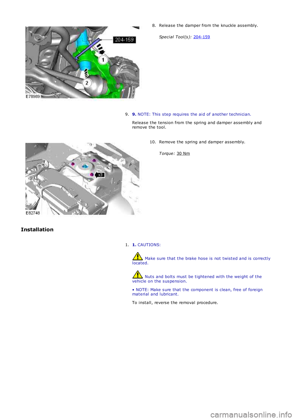
Releas e t he damper from t he knuckle as s embly.
Speci al Tool (s ): 204-159 8.
9. NOTE: Thi s s tep requires the ai d of anot her techni ci an.
Releas e t he tens ion from t he spring and damper as sembl y and
remove the t ool.
9. Remove t he s pring and damper as sembl y.
T orque: 30 Nm 10.
Installation 1. CAUTIONS: Make s ure that t he brake hos e is not t wis t ed and is correctl y
l ocated. Nut s and bolt s mus t be t ightened wi th the wei ght of t he
vehicle on the s us pens ion.
• NOTE: Make s ure that t he component is clean, free of foreign
mat eri al and l ubricant.
To i nst all , revers e t he removal procedure.
1.