2006 LAND ROVER FRELANDER 2 brake
[x] Cancel search: brakePage 121 of 3229
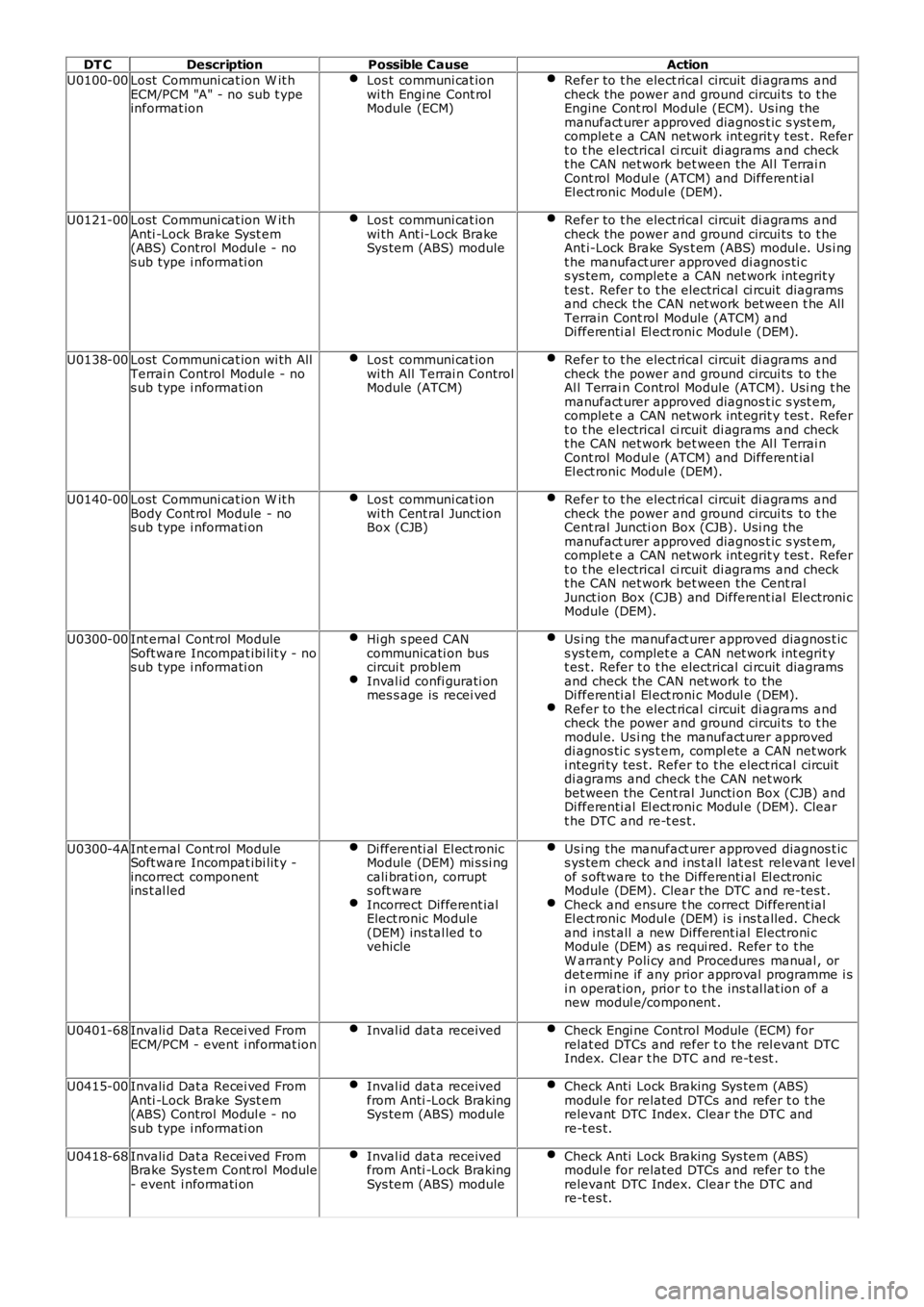
DT CDescriptionPossible CauseAction
U0100-00Lost Communi cat ion W it hECM/PCM "A" - no sub t ypeinformat ion
Los t communi cat ionwi th Engi ne Cont rolModule (ECM)
Refer to t he elect rical circuit di agrams andcheck the power and ground circui ts to t heEngine Cont rol Module (ECM). Us ing themanufact urer approved diagnos t ic s yst em,complet e a CAN network int egrit y t es t . Refert o t he electrical ci rcuit di agrams and checkt he CAN net work bet ween the Al l Terrai nCont rol Modul e (ATCM) and Different ialEl ect ronic Modul e (DEM).
U0121-00Lost Communi cat ion W it hAnti -Lock Brake Syst em(ABS) Control Modul e - nos ub type i nformati on
Los t communi cat ionwi th Ant i-Lock BrakeSys tem (ABS) module
Refer to t he elect rical circuit di agrams andcheck the power and ground circui ts to t heAnt i-Lock Brake Sys t em (ABS) modul e. Us i ngt he manufact urer approved di agnos ti cs ys tem, complet e a CAN net work int egrit yt es t. Refer t o t he electrical ci rcuit diagramsand check the CAN net work bet ween t he AllTerrain Cont rol Module (ATCM) andDi fferenti al El ect roni c Modul e (DEM).
U0138-00Lost Communi cat ion wi th AllTerrai n Control Modul e - nos ub type i nformati on
Los t communi cat ionwi th All Terrai n ControlModule (ATCM)
Refer to t he elect rical circuit di agrams andcheck the power and ground circui ts to t heAl l Terrai n Control Module (ATCM). Usi ng t hemanufact urer approved diagnos t ic s yst em,complet e a CAN network int egrit y t es t . Refert o t he electrical ci rcuit di agrams and checkt he CAN net work bet ween the Al l Terrai nCont rol Modul e (ATCM) and Different ialEl ect ronic Modul e (DEM).
U0140-00Lost Communi cat ion W it hBody Cont rol Module - nos ub type i nformati on
Los t communi cat ionwi th Cent ral Junct ionBox (CJB)
Refer to t he elect rical circuit di agrams andcheck the power and ground circui ts to t heCent ral Juncti on Box (CJB). Usi ng themanufact urer approved diagnos t ic s yst em,complet e a CAN network int egrit y t es t . Refert o t he electrical ci rcuit di agrams and checkt he CAN net work bet ween the Cent ralJunct ion Box (CJB) and Different ial Electroni cModule (DEM).
U0300-00Int ernal Cont rol ModuleSoft ware Incompat ibi lit y - nos ub type i nformati on
Hi gh s peed CANcommunicati on buscircui t problemInval id confi gurati onmes s age is recei ved
Us i ng the manufact urer approved diagnos t ics ys tem, complet e a CAN net work int egrit yt es t. Refer t o t he electrical ci rcuit diagramsand check the CAN net work to theDi fferenti al El ect roni c Modul e (DEM).Refer to t he elect rical circuit di agrams andcheck the power and ground circui ts to t hemodul e. Us i ng the manufact urer approveddi agnos ti c s ys t em, compl ete a CAN net worki ntegri ty tes t. Refer to t he elect rical circuitdi agrams and check t he CAN net workbet ween the Cent ral Juncti on Box (CJB) andDi fferenti al El ect roni c Modul e (DEM). Cleart he DTC and re-t es t.
U0300-4AInt ernal Cont rol ModuleSoft ware Incompat ibi lit y -incorrect componentins t al led
Di fferenti al El ect ronicModule (DEM) mi s si ngcali brati on, corrupts oft wareIncorrect Different ialElect ronic Module(DEM) ins tal led t ovehicle
Us i ng the manufact urer approved diagnos t ics ys tem check and i ns t all lat est relevant l evelof s oft ware to the Di fferenti al El ect ronicModule (DEM). Clear the DTC and re-tes t .Check and ensure t he correct Different ialEl ect ronic Modul e (DEM) i s i ns t alled. Checkand i nst all a new Different ial Electroni cModule (DEM) as requi red. Refer t o t heW arrant y Poli cy and Procedures manual , ordet ermi ne if any prior approval programme i si n operat ion, prior t o t he ins t al lat ion of anew modul e/component .
U0401-68Invali d Dat a Recei ved FromECM/PCM - event i nformat ionInval id dat a receivedCheck Engi ne Control Module (ECM) forrelat ed DTCs and refer t o t he rel evant DTCIndex. Cl ear t he DTC and re-t est .
U0415-00Invali d Dat a Recei ved FromAnti -Lock Brake Syst em(ABS) Control Modul e - nos ub type i nformati on
Inval id dat a receivedfrom Anti -Lock BrakingSys tem (ABS) module
Check Anti Lock Braking Sys tem (ABS)modul e for related DTCs and refer t o t herelevant DTC Index. Clear the DTC andre-t es t.
U0418-68Invali d Dat a Recei ved FromBrake Sys tem Cont rol Module- event i nformati on
Inval id dat a receivedfrom Anti -Lock BrakingSys tem (ABS) module
Check Anti Lock Braking Sys tem (ABS)modul e for related DTCs and refer t o t herelevant DTC Index. Clear the DTC andre-t es t.
Page 147 of 3229
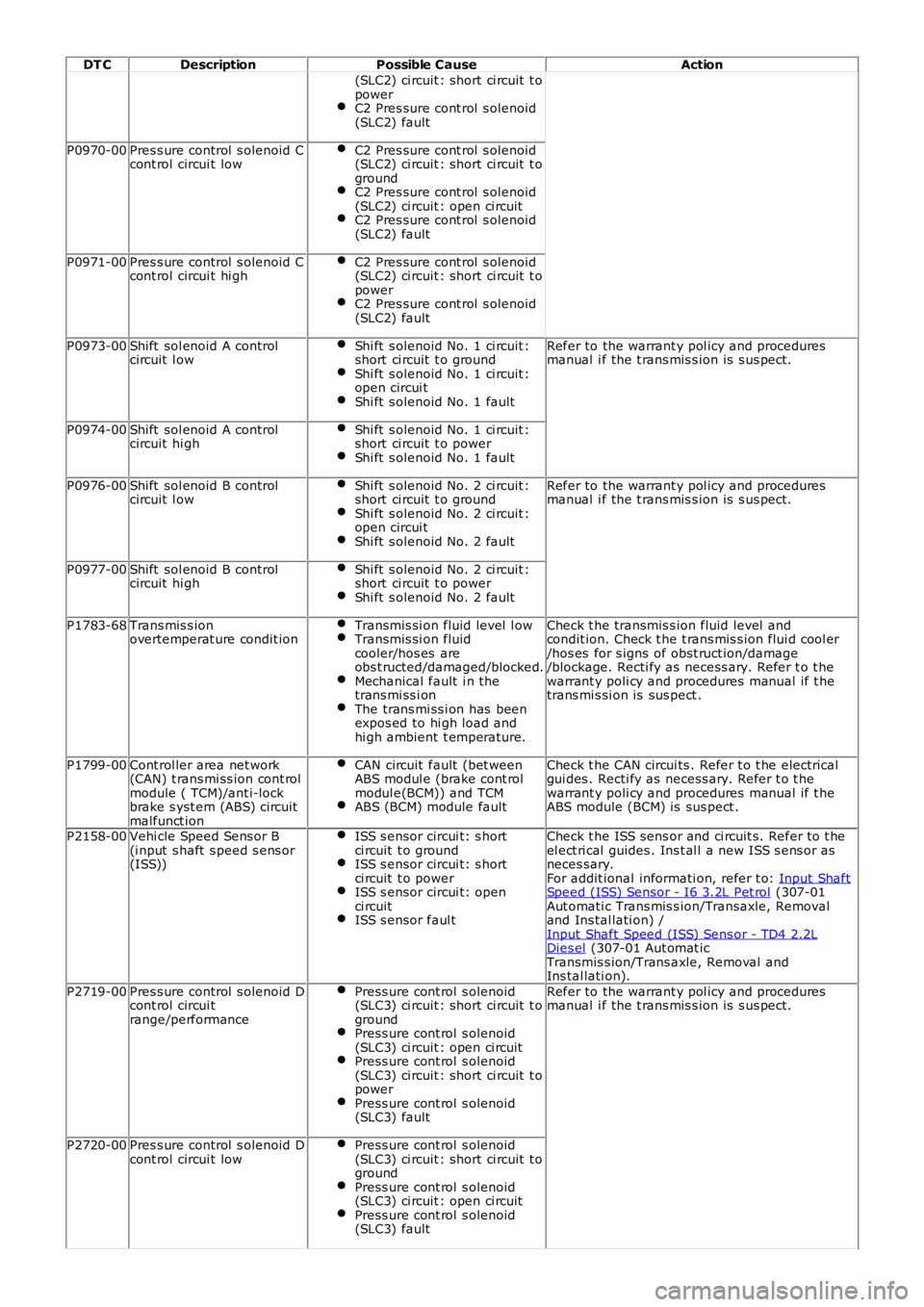
DT C
Description Possible Cause Action
(SLC2) ci rcuit : short ci rcuit t o
power
C2 Pres sure cont rol s olenoid
(SLC2) fault P0970-00
Pres s ure control s olenoid C
cont rol circui t low C2 Pres sure cont rol s olenoid
(SLC2) ci rcuit : short ci rcuit t o
ground C2 Pres sure cont rol s olenoid
(SLC2) ci rcuit : open ci rcuit C2 Pres sure cont rol s olenoid
(SLC2) fault P0971-00
Pres s ure control s olenoid C
cont rol circui t hi gh C2 Pres sure cont rol s olenoid
(SLC2) ci rcuit : short ci rcuit t o
power C2 Pres sure cont rol s olenoid
(SLC2) fault P0973-00
Shift sol enoid A control
circuit l ow Shi ft s olenoid No. 1 ci rcuit :
short ci rcuit t o ground Shi ft s olenoid No. 1 ci rcuit :
open circui t Shi ft s olenoid No. 1 fault Refer to the warrant y pol icy and procedures
manual i f the t rans mis s ion is s us pect.
P0974-00 Shift sol enoid A control
circuit hi gh Shi ft s olenoid No. 1 ci rcuit :
short ci rcuit t o power Shi ft s olenoid No. 1 fault
P0976-00
Shift sol enoid B control
circuit l ow Shi ft s olenoid No. 2 ci rcuit :
short ci rcuit t o ground Shi ft s olenoid No. 2 ci rcuit :
open circui t Shi ft s olenoid No. 2 fault Refer to the warrant y pol icy and procedures
manual i f the t rans mis s ion is s us pect.
P0977-00 Shift sol enoid B control
circuit hi gh Shi ft s olenoid No. 2 ci rcuit :
short ci rcuit t o power Shi ft s olenoid No. 2 fault
P1783-68
Trans mis s ion
overtemperat ure condit ion Transmis si on fluid level l ow Transmis si on fluid
cooler/hos es are
obs t ructed/damaged/blocked. Mechanical fault i n the
trans mi ss i on The trans mi ss i on has been
expos ed to hi gh load and
hi gh ambient t emperature. Check t he transmis s ion fluid level and
condit ion. Check t he t rans mis s ion flui d cool er
/hos es for s igns of obst ruct ion/damage
/blockage. Recti fy as necess ary. Refer t o t he
warrant y poli cy and procedures manual if t he
trans mi s si on is sus pect .
P1799-00 Cont rol ler area net work
(CAN) t rans mi ss ion cont rol
module ( TCM)/ant i-lock
brake s yst em (ABS) circuit
malfunct ion CAN circuit fault (bet ween
ABS modul e (brake cont rol
modul e(BCM)) and TCM ABS (BCM) module fault Check t he CAN circui ts . Refer t o t he electrical
gui des . Recti fy as necess ary. Refer t o t he
warrant y poli cy and procedures manual if t he
ABS module (BCM) is sus pect .
P2158-00 Vehi cle Speed Sens or B
(i nput s haft s peed s ens or
(ISS)) ISS s ensor circui t: s hort
ci rcuit t o ground ISS s ensor circui t: s hort
ci rcuit t o power ISS s ensor circui t: open
ci rcuit ISS s ensor faul t Check t he ISS sens or and ci rcuit s. Refer to t he
el ect ri cal guides . Ins t al l a new ISS s ens or as
neces sary.
For addit ional informati on, refer t o: Input Shaft Speed (ISS) Sensor - I6 3.2L Pet rol (307-01
Aut omati c Trans mis s ion/Transaxle, Removal
and Ins tal lati on) /
Input Shaft Speed (ISS) Sens or - TD4 2.2L Dies el (307-01 Aut omat ic
Transmis s ion/Trans axle, Removal and
Ins tal lati on).
P2719-00 Pres s ure control s olenoid D
cont rol circui t
range/performance Press ure cont rol s olenoid
(SLC3) ci rcuit : short ci rcuit t o
ground Press ure cont rol s olenoid
(SLC3) ci rcuit : open ci rcuit Press ure cont rol s olenoid
(SLC3) ci rcuit : short ci rcuit t o
power Press ure cont rol s olenoid
(SLC3) fault Refer to the warrant y pol icy and procedures
manual i f the t rans mis s ion is s us pect.
P2720-00 Pres s ure control s olenoid D
cont rol circui t low Press ure cont rol s olenoid
(SLC3) ci rcuit : short ci rcuit t o
ground Press ure cont rol s olenoid
(SLC3) ci rcuit : open ci rcuit Press ure cont rol s olenoid
(SLC3) fault
Page 149 of 3229
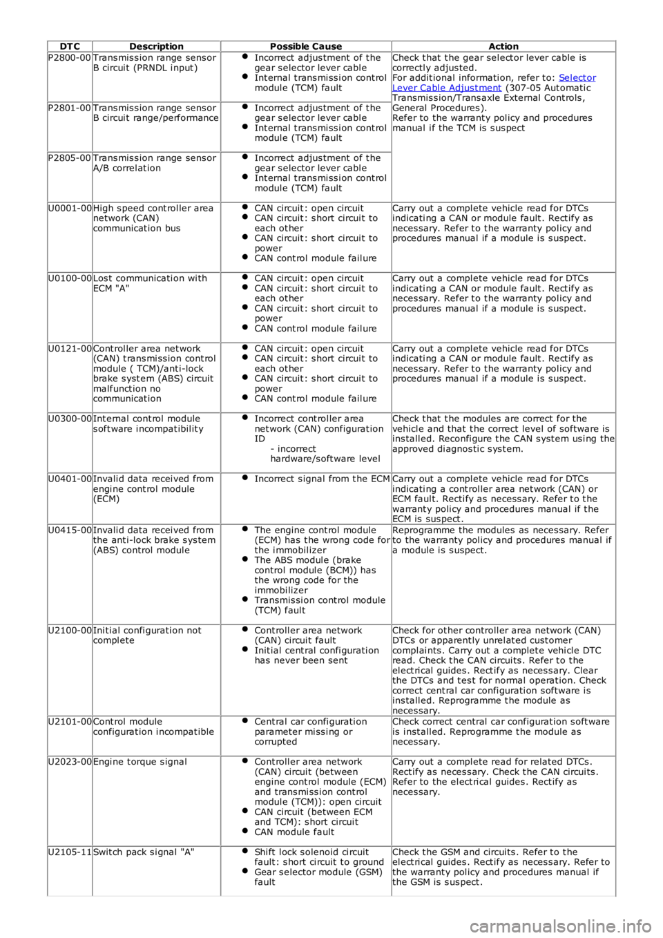
DT C
Description Possible Cause Action
P2800-00 Trans mis s ion range sens or
B circui t (PRNDL i nput ) Incorrect adjus tment of t he
gear s elector lever cabl e Int ernal t rans mi ss i on cont rol
modul e (TCM) fault Check t hat t he gear sel ect or lever cable is
correctl y adjus ted.
For addit ional informati on, refer t o: Sel ect or Lever Cabl e Adjus t ment (307-05 Aut omati c
Transmis s ion/Trans axle External Cont rols ,
General Procedures ).
Refer to the warrant y pol icy and procedures
manual i f the TCM is s us pect
P2801-00
Trans mis s ion range sens or
B circui t range/performance Incorrect adjus tment of t he
gear s elector lever cabl e Int ernal t rans mi ss i on cont rol
modul e (TCM) fault P2805-00
Trans mis s ion range sens or
A/B correl at ion Incorrect adjus tment of t he
gear s elector lever cabl e Int ernal t rans mi ss i on cont rol
modul e (TCM) fault U0001-00
High s peed cont rol ler area
network (CAN)
communicat ion bus CAN circuit : open circuit CAN circuit : s hort circui t to
each ot her CAN circuit : s hort circui t to
power CAN cont rol module fail ure Carry out a compl ete vehicle read for DTCs
indicati ng a CAN or module fault . Rect ify as
neces sary. Refer t o t he warranty pol icy and
procedures manual if a module i s s uspect.
U0100-00 Los t communicati on wi th
ECM "A" CAN circuit : open circuit CAN circuit : s hort circui t to
each ot her CAN circuit : s hort circui t to
power CAN cont rol module fail ure Carry out a compl ete vehicle read for DTCs
indicati ng a CAN or module fault . Rect ify as
neces sary. Refer t o t he warranty pol icy and
procedures manual if a module i s s uspect.
U0121-00 Cont rol ler area net work
(CAN) t rans mi ss ion cont rol
module ( TCM)/ant i-lock
brake s yst em (ABS) circuit
malfunct ion no
communicat ion CAN circuit : open circuit CAN circuit : s hort circui t to
each ot her CAN circuit : s hort circui t to
power CAN cont rol module fail ure Carry out a compl ete vehicle read for DTCs
indicati ng a CAN or module fault . Rect ify as
neces sary. Refer t o t he warranty pol icy and
procedures manual if a module i s s uspect.
U0300-00 Int ernal cont rol module
s oft ware i ncompat ibil it y Incorrect cont rol ler area
net work (CAN) configurat ion
ID
- incorrect
hardware/s oft ware level Check t hat t he modules are correct for the
vehicl e and that t he correct level of software is
ins tall ed. Reconfi gure t he CAN s yst em us i ng the
approved di agnos ti c s ys t em.
U0401-00 Invali d data recei ved from
engi ne cont rol module
(ECM) Incorrect s ignal from t he ECM Carry out a compl ete vehicle read for DTCs
indicati ng a cont rol ler area net work (CAN) or
ECM faul t. Recti fy as necess ary. Refer t o t he
warrant y poli cy and procedures manual if t he
ECM is sus pect .
U0415-00 Invali d data recei ved from
the ant i-lock brake s ys tem
(ABS) control modul e The engine cont rol module
(ECM) has t he wrong code for
the i mmobil izer The ABS modul e (brake
control modul e (BCM)) has
the wrong code for the
immobi lizer Transmis si on cont rol module
(TCM) faul t Reprogramme the modules as neces sary. Refer
to the warranty pol icy and procedures manual if
a module i s s uspect.
U2100-00 Ini ti al confi gurati on not
compl ete Cont roll er area network
(CAN) circui t fault Init ial cent ral confi gurati on
has never been sent Check for ot her controll er area network (CAN)
DTCs or apparent ly unrel at ed cust omer
compl ai nts . Carry out a complet e vehi cl e DTC
read. Check t he CAN circui ts . Refer t o t he
el ect ri cal guides . Rect ify as neces s ary. Clear
the DTCs and t es t for normal operat ion. Check
correct cent ral car confi gurati on s oftware i s
ins tall ed. Reprogramme t he module as
neces sary.
U2101-00 Cont rol module
configurat ion i ncompat ible Cent ral car confi gurati on
parameter mi ss i ng or
corrupted Check correct central car configurat ion s oft ware
is i nst all ed. Reprogramme t he module as
neces sary.
U2023-00 Engi ne t orque s ignal Cont roll er area network
(CAN) circui t (between
engine cont rol module (ECM)
and trans mi ss i on cont rol
modul e (TCM)): open ci rcuit CAN circuit (between ECM
and TCM): s hort circui t CAN module fault Carry out a compl ete read for related DTCs .
Rect ify as neces s ary. Check t he CAN circui ts .
Refer to the el ect ri cal guides . Rect ify as
neces sary.
U2105-11 Swit ch pack s i gnal "A" Shi ft l ock s olenoid ci rcuit
fault : s hort ci rcuit t o ground Gear s elector module (GSM)
fault Check t he GSM and circui ts . Refer t o t he
el ect ri cal guides . Rect ify as neces s ary. Refer to
the warrant y pol icy and procedures manual if
the GSM is s us pect .
Page 163 of 3229
Publ is hed: 24-Jun-2011
Jacking and Lifting - Jacking
Des cript ion and Operat ion
General
W ARNING: The foll owing i nst ructi ons mus t be adhered to before rais i ng the vehicle off t he ground:
Posi ti on vehi cl e on a sol id, level surface.Apply t he parking brake.Select 'P' - PARK on automat ic t rans mis s ion sel ect or.Select 'N' - Neutral on manual t rans mis s ion.
W ARNING: If t he dri ve s haft(s ) are t o be di sconnect ed, i t wil l be neces s ary t o rai s e all four wheels off the ground inorder t hat t he s haft (s ) can be rot ated. DO NOT us e the cus tomer jack and ens ure that t he vehi cl e is adequatel y s upport edon axle s t ands . W i th the vehicle rai sed, it will be necess ary to releas e t he park brake and sel ect Neutral - 'N' in the mai nt ransmis s ion t o enabl e t he dri ve s haft(s ) to be rot ated.
• CAUTIO NS:
To avoid damage t o t he underbody components of t he vehi cle, the foll owing i ns t ructions mus t be adhered to:
Do not pos it ion jacks or axle s t ands under the foll owing component s :
Body s truct ure ot her t han any approved jacki ng or li ft ing point sRear subframeBumpersFuel l inesFuel t ankBrake l inesFront or rear s uspens ion armsSteering l inkageRear di fferenti al uni tTrans mis s ionEngi ne oil pan - See not e below
• NOTE: For certain repair operat ions, i t may be necess ary to support t he engine under t he oil pan. In thi s cas e, a bl ock ofhardwood or a rubber pad mus t be pos it ioned on t he jack li ft ing pad t o protect the oi l pan.
Hydraulic jack
• W ARNINGS:
Before commenci ng work on undersi de of vehi cl e, ens ure that axle s t ands are correctly pos it ioned and vehi cle i ss ecurel y s upported.
Al ways chock the rear wheel s when jacking t he front of the vehicle.
A hydrauli c jack wi th a mi ni mum li ft ing capacit y of 1500 kg, (3,300 l bs) must be us ed.
Raising and Supporting the Vehicle
To as si s t in rais ing the vehicle, us e t he cus t omer jacki ng poi nts on the s i ll or on t he trolley jack pos i ti on at the rear of t hefront subframe as indicated i n t he fol lowing ill ust rat ions .
Raising the front of the vehicle
W ARNING: Always chock t he rear wheels when jacki ng the front of t he vehi cl e.
Apply t he parking brake.
Select 'P' - Park on aut omat ic trans mi s si on s el ect or.
Select 'N' - Neutral on manual t rans mis s ion.
Page 164 of 3229
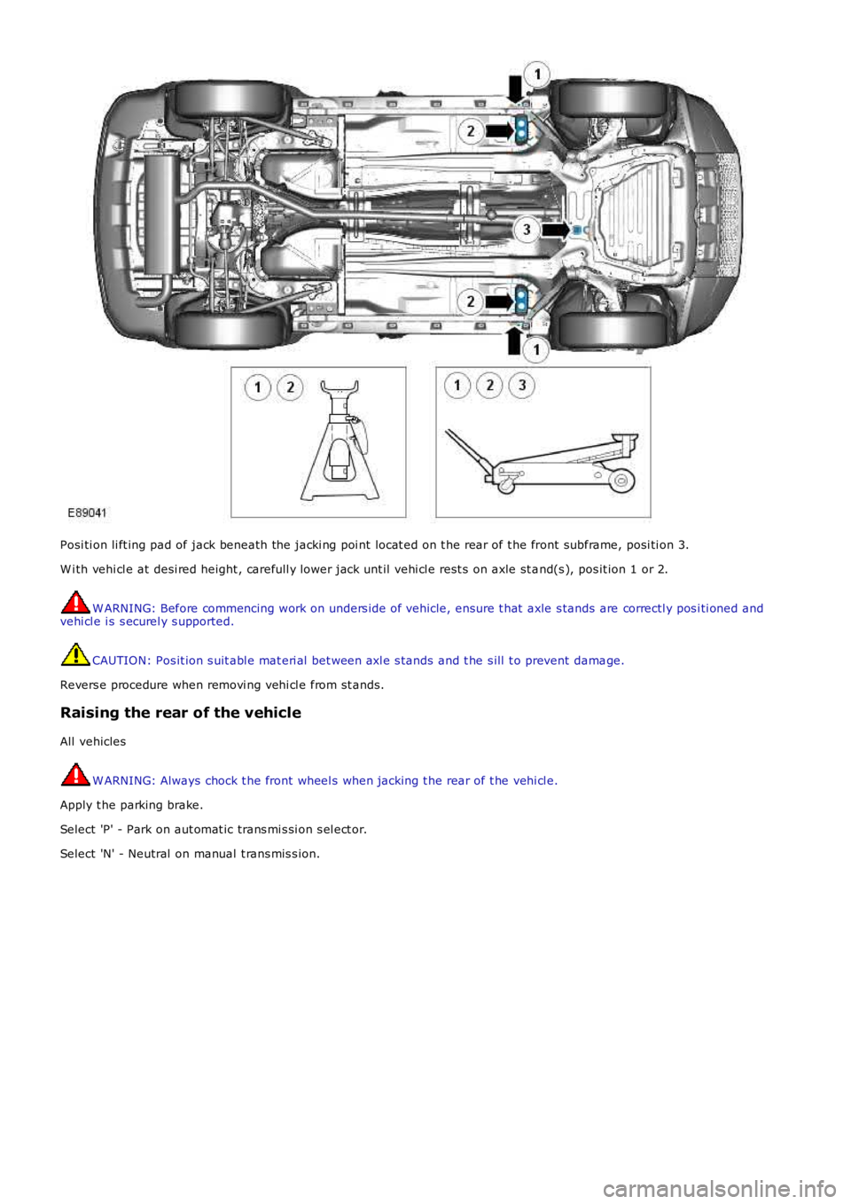
Posi ti on li ft ing pad of jack beneath the jacki ng poi nt locat ed on t he rear of t he front subframe, posi ti on 3.
W i th vehi cl e at desi red height , carefull y lower jack unt il vehi cl e rest s on axle st and(s ), pos it ion 1 or 2.
W ARNING: Before commencing work on unders ide of vehicle, ensure t hat axle s tands are correctl y pos i ti oned andvehi cl e i s s ecurel y s upported.
CAUTION: Pos it ion s uit abl e mat eri al bet ween axl e s tands and t he s ill t o prevent damage.
Revers e procedure when removi ng vehi cl e from st ands.
Raising the rear of the vehicle
All vehicles
W ARNING: Always chock t he front wheel s when jacking t he rear of t he vehi cl e.
Apply t he parking brake.
Select 'P' - Park on aut omat ic trans mi s si on s el ect or.
Select 'N' - Neutral on manual t rans mis s ion.
Page 166 of 3229

Publi s hed: 11-May-2011
Jacking and Lifting - Lifting
Des cript ion and Operat ion
Two-Post Lift
W ARNING: Make sure t hat t he vehicle i s s table before commencing work.
CAUTION: If the drive s haft (s ) are to be removed, rel eas e t he parking brake and s el ect NEUTRAL 'N' i n t het ransmis s ion i n order t hat t he s haft (s ) can be rot ated when the vehicle is rais ed to the des ired height.
1. Pos i ti on the vehicle wit h t he cent re of the l ift pill ars al igned approxi mat el y wi th t he front of the driver/pass enger s eatcus hions .
ItemPart NumberDescription
1-Two post l ift locati ons - Cus t omer jacki ng points2-Opti onal, Two-pos t front li ft l ocat ions - Body mounti ng us ed in vehicle product ion
2. Ext end t he li ft ing arms and pos it ion t he pad of each l ifti ng arm beneat h t he approved poi nt s .
3. Rais e t he vehi cl e unti l the wheels are just cl ear of t he ground and check t hat the pads of each lift ing arm are s ti llcorrect ly pos it ioned.
4. Rais e t he vehi cl e t o t he des i red height .
5. Ensure t he vehi cl e is correctl y s upport ed wi th the l ifti ng pads in full cont act with t he approved poi nt s .
Vehicle on wheels - Four-Post Ramp
• W ARNINGS:
If the drive s haft (s ) are t o be dis connected, it will be necess ary to rais e al l four wheel s off t he ramp in order thatt he shaft(s ) can be rot at ed. Refer to the 'W heel Free Lift - Four-Pos t Ramp' s ecti on below for li ft ing i ns t ructi ons thenrel eas e t he parki ng brake and s elect NEUTRAL i n t he transmis si on.
Do not pus h t he vehi cl e backwards and forwards along t he ramp in order to gai n acces s t o the drive s haft fixi ngs .
Posi ti on t he vehi cl e on t he ramp wit h t he front and rear wheel s equidis t ant from t he ends of t he ramp. Chock t he wheel s,s elect NEUTRAL i n t he transmis si on and where pract ical, apply the parki ng brake.
Wheel-Free Lift - Four-Post Ramp
Page 167 of 3229
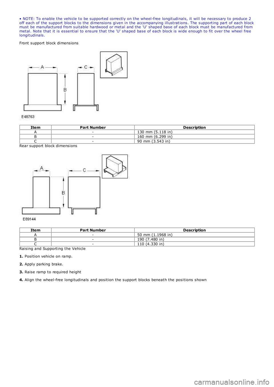
• NOTE: To enable t he vehi cle t o be s upport ed correctl y on t he wheel -free longit udi nal s, i t wil l be neces s ary t o produce 2off each of the support blocks t o the di mens ions given in the accompanying ill ust rations . The s upport ing part of each bl ockmus t be manufactured from s uit able hardwood or met al and the 'U' shaped bas e of each bl ock mus t be manufact ured frommet al . Note that it i s es sent ial to ens ure that t he 'U' s haped bas e of each block is wide enough to fit over t he wheel freelongit udinals .
Front s upport bl ock di mens ions
ItemPart NumberDescriptionA-130 mm (5.118 in)
B-160 mm (6.299 in)
C-90 mm (3.543 in)Rear support block dimens i ons
ItemPart NumberDescription
A-50 mm (1.1968 in)B-190 (7.480 in)
C-110 (4.330 in)
Rais ing and Support ing t he Vehicle
1. Posi ti on vehi cl e on ramp.
2. Appl y parking brake.
3. Rais e ramp t o required height
4. Ali gn the wheel -free l ongi tudinals and pos it ion the s upport blocks beneat h the pos it ions s hown
Page 169 of 3229

Publi s hed: 11-May-2011
Jacking and Lifting - Vehicle Recovery
Des cript ion and Operat ion
Towing Points
CAUTION: The s ingle towi ng poi nts at t he front and rear of t he vehi cl e are des igned for vehicl e recovery purpos esonly and mus t NOT be used to t ow a trail er or caravan.
The front towi ng eye is acces s ibl e aft er releas ing t he 2 t oggle fast eners s ecuring the t owing eye acces s panel andremovi ng the panel.
CAUTION: Ens ure t hat during t owing, the towi ng att achment does not contact t he bumper.
The rear t owing eye i s acces si ble after rel eas i ng the 2 toggle fas teners securi ng the towing eye access panel and removingt he panel.
CAUTION: This t owing eye s hould onl y be us ed for t owing another vehi cl e or for recovery purpos es .
Towing the vehicle on four wheels
• W ARNINGS:
Ens ure t hat the remote cont rol remai ns docked whil s t the vehicle is being towed. Removi ng the remot e cont rol wi llengage t he s t eering l ock, which wi ll prevent the vehicle from s t eering correct ly.
If the engine cannot be run whi ls t t he vehi cl e i s bei ng t owed, t here wi ll be no power as si s tance for t he s teeri ng orbrakes. Thi s wil l res ult in greater effort bei ng required to st eer or sl ow t he vehi cl e, and greatl y increas ed s toppingdis t ances.
• CAUTIO NS:
The vehicle s hould onl y be t owed wit h four wheels on the ground. Towing wi th two wheel s on t he ground wi ll res ultin serious damage t o t he trans mi s si on.
The vehicle s hould onl y be t owed for a maxi mum of 80 km (50 mil es), at a maximum s peed of 80 km/h (50 mph).Towing for a great er di st ance, or at a higher s peed may res ult i n s eri ous damage t o t he t rans mis s ion.
• NOTE: The recommended recovery met hod is to rais e al l four wheel s.
Towing procedure
1. The vehi cl e s houl d be parked on firm level ground, wi th t he park brake on, and the gear s el ect or in P if an aut omati cgearbox is fit t ed.
2. Secure the towing at t achment from the recovery vehicle to the front t owing eye.
CAUTION: Leavi ng the ignit ion s wi tched on for extended peri ods wil l caus e the bat tery t o drai n.
3. Dock the remote cont rol, and s wi tch on t he igni ti on.
4. Appl y t he foot brake, and s el ect neutral.
5. W i th the foot brake s t ill appli ed, releas e the park brake.