Page 233 of 3229

The t op mount at t aches t o a s t rengthened turret on t he chas s is wit h 3 i ntegral s tuds and s elf-l ocking nut s .
Two brackets are welded t o t he damper body. One bracket provides for t he att achment of t he s tabil izer li nk. The s econdbracket provi des for t he att achment of t he brake hose and wheel s peed s ens or cabl e. This bracket als o pos it ively locat est he damper i nto t he wheel knuckle and i ts locat ion i s cri ti cal t o cont rol li ng the vehicle trim height.
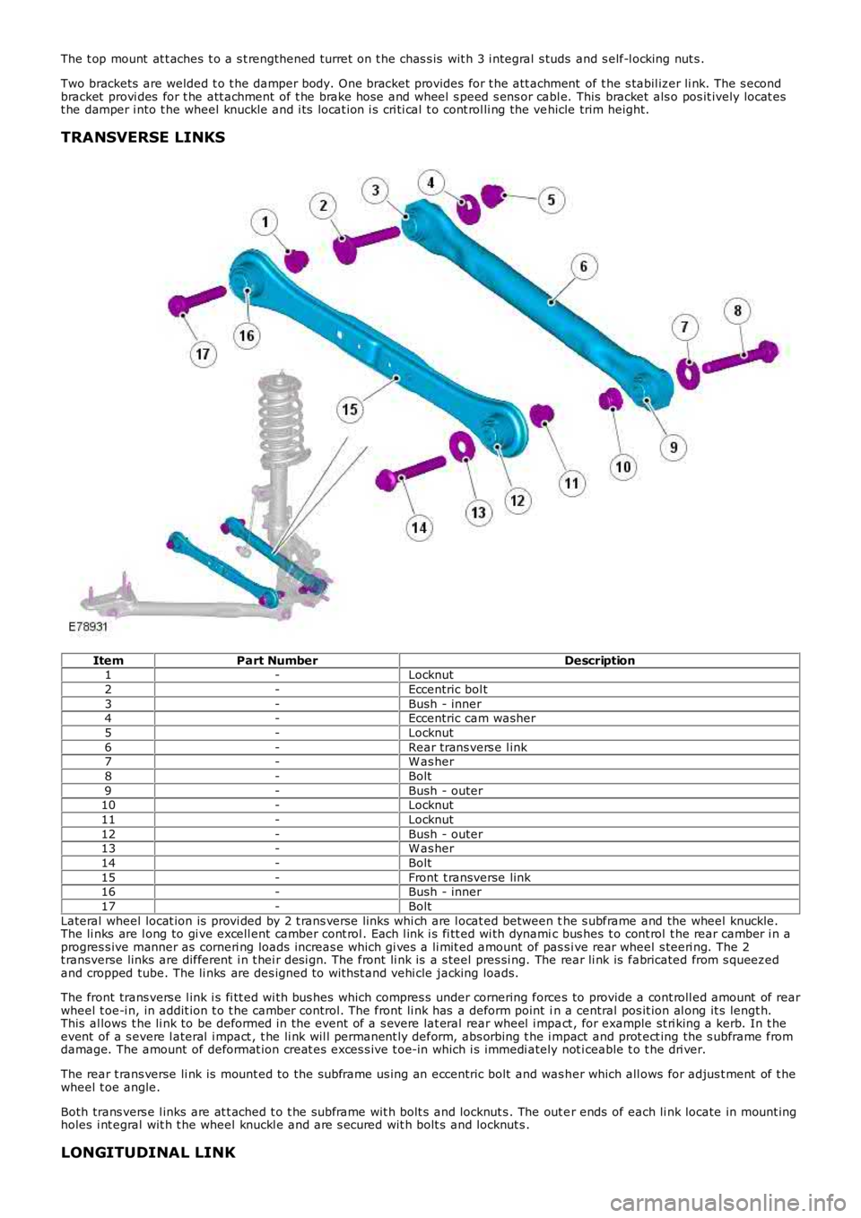
TRANSVERSE LINKS
ItemPart NumberDescription1-Locknut
2-Eccentric bol t
3-Bush - inner4-Eccentric cam washer
5-Locknut
6-Rear trans vers e l ink7-W as her
8-Bolt
9-Bush - outer10-Locknut
11-Locknut
12-Bush - outer13-W as her
14-Bolt
15-Front t ransverse link16-Bush - inner
17-Bolt
Lateral wheel locat ion is provi ded by 2 t rans verse li nks whi ch are l ocat ed between the s ubframe and the wheel knuckle.The li nks are l ong to gi ve excell ent camber cont rol . Each l ink i s fi tt ed wi th dynamic bus hes t o cont rol t he rear camber i n aprogres s ive manner as corneri ng loads increas e which gi ves a li mit ed amount of pas s ive rear wheel s teeri ng. The 2t ransverse links are different i n t hei r des i gn. The front li nk is a s teel pres si ng. The rear li nk is fabricated from s queezedand cropped tube. The li nks are des igned to wit hst and vehi cle jacking loads.
The front trans vers e l ink i s fi tt ed wi th bus hes which compres s under cornering forces to provide a cont roll ed amount of rearwheel t oe-i n, in addit ion t o t he camber control. The front li nk has a deform point in a central pos it ion al ong it s lengt h.This al lows t he li nk to be deformed in the event of a s evere lat eral rear wheel i mpact , for example st ri king a kerb. In t heevent of a s evere l ateral i mpact , t he li nk wil l permanent ly deform, abs orbing t he i mpact and prot ect ing the s ubframe fromdamage. The amount of deformat ion creat es exces s ive t oe-in which i s immedi ately not iceable t o t he dri ver.
The rear t rans verse li nk is mount ed to the subframe us ing an eccentric bolt and was her which all ows for adjus t ment of t hewheel t oe angle.
Both trans vers e l inks are at t ached t o t he s ubframe wit h bolt s and locknut s . The out er ends of each li nk locate in mount ingholes i nt egral wit h t he wheel knuckl e and are s ecured wit h bolt s and locknut s .
LONGITUDINAL LINK
Page 235 of 3229

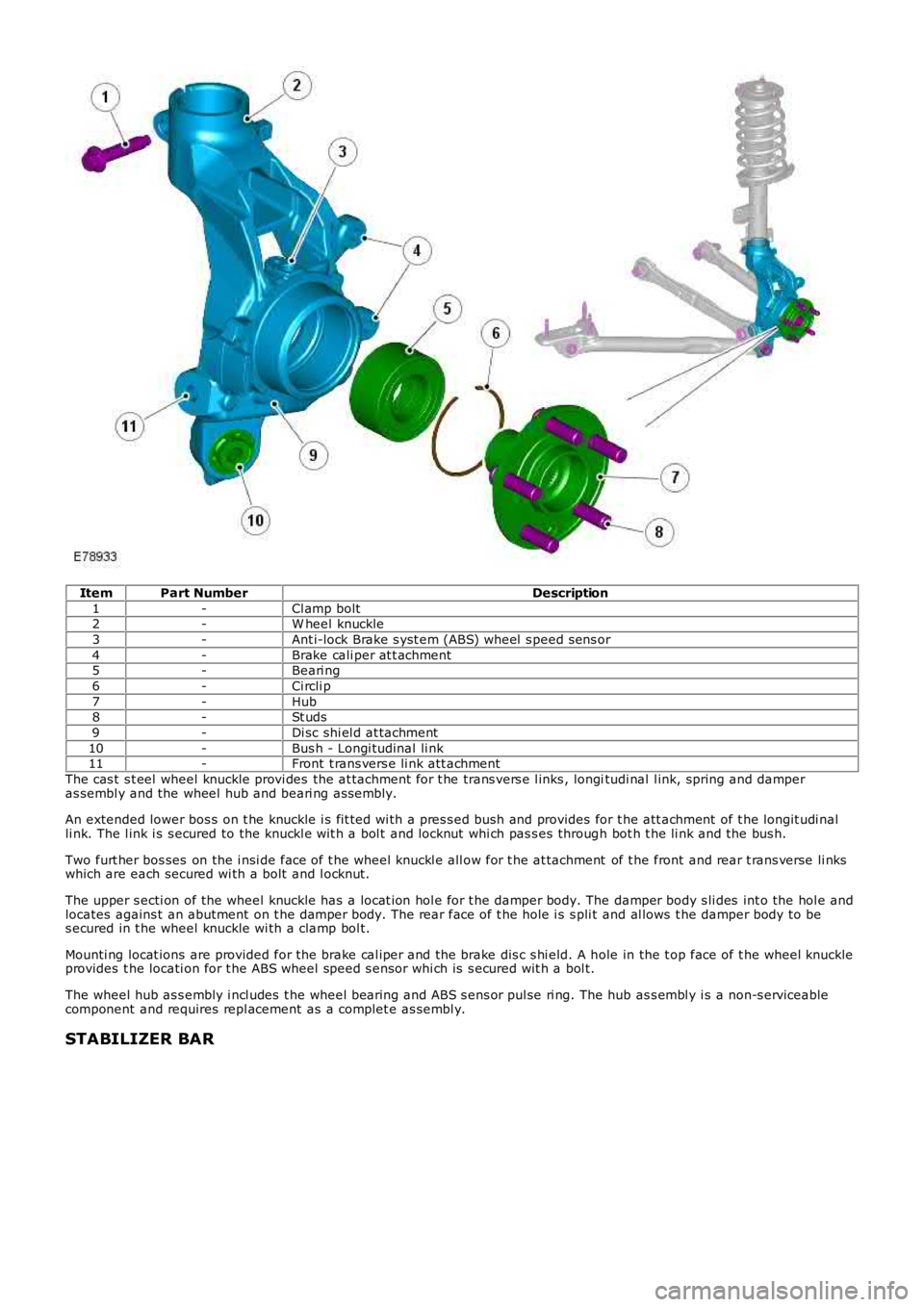
ItemPart NumberDescription
1-Cl amp bolt2-W heel knuckle
3-Ant i-lock Brake s yst em (ABS) wheel s peed s ens or
4-Brake cali per at t achment5-Beari ng
6-Ci rcli p
7-Hub8-St uds
9-Di sc shi el d at tachment
10-Bus h - Longi tudinal li nk11-Front t rans vers e li nk att achment
The cas t s t eel wheel knuckle provi des the at tachment for t he trans vers e l inks , longitudi nal l ink, spring and damperas sembl y and the wheel hub and beari ng ass embly.
An extended lower bos s on t he knuckle i s fit ted wi th a pres s ed bush and provides for t he att achment of t he longit udi nalli nk. The l ink i s s ecured to the knuckl e wit h a bol t and locknut whi ch pas s es through bot h t he li nk and the bus h.
Two furt her bos ses on the i nsi de face of t he wheel knuckl e all ow for t he at tachment of t he front and rear t rans verse li nkswhich are each secured wi th a bolt and l ocknut.
The upper s ecti on of the wheel knuckle has a locat ion hol e for t he damper body. The damper body s li des int o the hol e andlocates agains t an abutment on t he damper body. The rear face of t he hole i s s pli t and al lows t he damper body to bes ecured in t he wheel knuckle wi th a clamp bol t.
Mounti ng locat ions are provided for the brake cal iper and the brake dis c s hi eld. A hole in the t op face of t he wheel knuckl eprovides t he locati on for t he ABS wheel speed s ensor whi ch is s ecured wit h a bol t.
The wheel hub as s embly i ncl udes t he wheel bearing and ABS s ens or pul se ri ng. The hub as s embl y i s a non-s erviceablecomponent and requires repl acement as a complet e as sembl y.
STABILIZER BAR
Page 242 of 3229

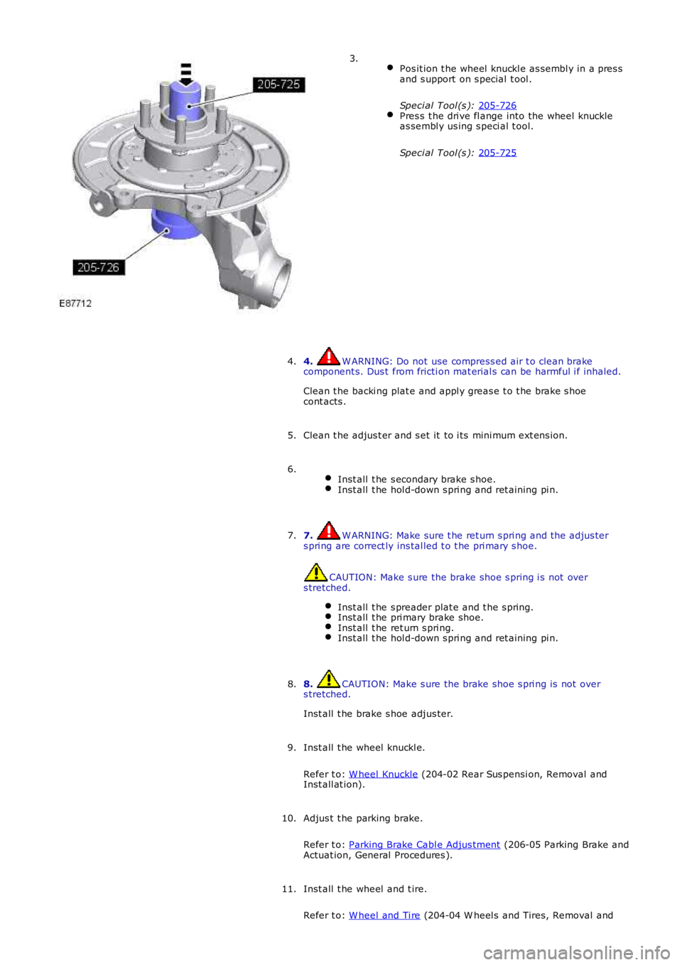
Pos it ion t he wheel knuckl e as sembl y in a pres s
and s upport on s pecial t ool .
Speci al Tool (s ): 205-726 Pres s t he dri ve fl ange into the wheel knuckle
as sembl y us ing s peci al t ool.
Speci al Tool (s ): 205-725 3.
4. W ARNING: Do not use compress ed air t o clean brake
component s. Dus t from fricti on mat erial s can be harmful i f inhaled.
Clean t he backi ng plat e and appl y greas e t o t he brake s hoe
cont acts .
4.
Clean t he adjus t er and s et it to i ts mini mum ext ens ion.
5.
Inst all t he s econdary brake s hoe. Inst all t he hol d-down s pri ng and ret aining pi n.6.
7. W ARNING: Make sure t he ret urn s pri ng and t he adjus ter
s pri ng are correct ly ins tal led t o t he pri mary s hoe. CAUTION: Make s ure the brake shoe s pring i s not over
s tretched.
Inst all t he s preader plat e and t he s pring. Inst all t he pri mary brake shoe.
Inst all t he ret urn s pri ng.
Inst all t he hol d-down s pri ng and ret aining pi n.7.
8. CAUTION: Make s ure the brake shoe s pri ng is not over
s tretched.
Inst all t he brake s hoe adjus ter.
8.
Inst all t he wheel knuckl e.
Refer t o: W heel Knuckle (204-02 Rear Sus pensi on, Removal and
Inst all at ion).
9.
Adjus t t he parking brake.
Refer t o: Parking Brake Cabl e Adjus tment (206-05 Parking Brake and
Actuat ion, General Procedures ).
10.
Inst all t he wheel and t ire.
Refer t o: W heel and Ti re (204-04 W heel s and Tires, Removal and
11.
Page 244 of 3229
6.
Installation Inst all t he front lower arm.
1.
2. CAUTION: Nut s and bol ts mus t be ti ght ened wit h t he weight
of t he vehi cl e on t he s us pensi on.
Inst all t he nut s , bol ts and washers, do not t ighten at this st age.
2.
3. CAUTION: Nut s and bol ts mus t be ti ght ened wit h t he weight
of t he vehi cl e on t he s us pensi on.
Support weight of vehi cl e on a jack at the rear hub.
3.
Tight en the nut s and bolt s.
T orque: 175 Nm 4.
5. W ARNING: Make sure t hat a new bolt i s ins tal led.
Inst all t he parking brake cable ret ai ning bolt .
T orque: 10 Nm 5.
Inst all t he rear wheel.
Refer t o: W heel and Ti re (204-04 W heel s and Tires, Removal and
Inst all at ion).
6.
Check and if neces s ary, adjus t the rear wheel ali gnment
7.
Page 253 of 3229
4. CAUTION: Di scard the nut .
• NOTE: RH ill ust rat ion shown, LH i s s imi lar.
4.
Releas e t he wheel s peed s ens or from t he wheelknuckle.5.
6. CAUTION: Make s ure that no load i s placed ont he brake hos e.
Tie the brake cal iper and brake cal iper anchorplat e as sembl y as ide.
6.
Page 254 of 3229
Releas e t he park brake s hoe adjus t ment .7.
Remove t he brake dis c.8.
Releas e t he parking brake cable from t he wheelknuckle.Coll ect t he cli p.
9.
Page 259 of 3229
Pos it ion t he wheel knuckl e as sembl y in a pres s
and s upport on s pecial t ool s .
Speci al Tool (s ): 205-728 Pres s t he wheel bearing out of the wheel
knuckle ass embly us i ng s pecial t ool .
Speci al Tool (s ): 205-726 22.
Remove t he brake backi ng plate.
23. 24. CAUTION: Mark the component s t o aid
i ns t allat ion.
Remove t he wheel knuckl e bushi ng.
Speci al Tool (s ): LR-121 ,
204-620-02 ,
204-620-03 24.
Installation
Page 260 of 3229
1. CAUTION: Make s ure that the ins tall ati on
marks are al igned.
1. 2. CAUTION: Make s ure the correct s peci al tool is
us ed to ins tal l the bus hings to the correct dept h.
Inst all t he wheel knuckl e bushi ng.
Speci al Tool (s ): LR-121 ,
204-620-01 ,
204-620-02 2.
Inst all t he brake backi ng plate.
3. 4. CAUTION: One s i de of the beari ng is magnet ic.
The magneti c s ide i s identi fi abl e by t he appl icati on of a
mat t black fi nis h. The magnet ic s i de mus t face t owards
t he inboard s i de of the vehicle. Before fit ti ng the
beari ng, make s ure the magnet ic face is clean. The
beari ng mus t be handl ed wit h extreme care.
Pos it ion t he wheel knuckl e as sembl y in a pres s
and s upport on s pecial t ool .
Speci al Tool (s ): 204-528/2 Pres s t he new wheel bearing i nto the wheel
knuckle ass embly us i ng s pecial t ool .
Speci al Tool (s ): 205-726 4.
Inst all t he ci rcli p t o t he wheel knuckl e as sembl y.
5.