2006 LAND ROVER FRELANDER 2 brake
[x] Cancel search: brakePage 261 of 3229
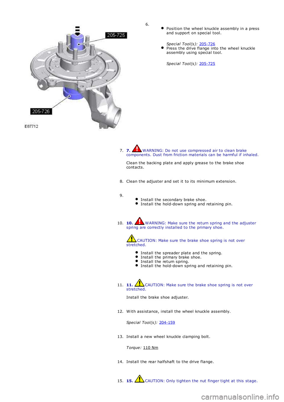
Pos it ion t he wheel knuckl e as sembl y in a pres s
and s upport on s pecial t ool .
Speci al Tool (s ): 205-726 Pres s t he dri ve fl ange into the wheel knuckle
as sembl y us ing s peci al t ool.
Speci al Tool (s ): 205-725 6.
7. W ARNING: Do not use compress ed air t o clean brake
component s. Dus t from fricti on mat erial s can be harmful i f inhaled.
Clean t he backi ng plat e and appl y greas e t o t he brake s hoe
cont acts .
7.
Clean t he adjus t er and s et it to i ts mini mum ext ens ion.
8.
Inst all t he s econdary brake s hoe. Inst all t he hol d-down s pri ng and ret aining pi n.9.
10. W ARNING: Make sure t he ret urn s pri ng and t he adjust er
s pri ng are correct ly ins tal led t o t he pri mary s hoe. CAUTION: Make s ure the brake shoe s pring i s not over
s tretched.
Inst all t he s preader plat e and t he s pring. Inst all t he pri mary brake shoe.
Inst all t he ret urn s pri ng.
Inst all t he hol d-down s pri ng and ret aining pi n.10.
11. CAUTION: Make s ure t he brake s hoe s pri ng is not over
s tretched.
Inst all t he brake s hoe adjus ter.
11.
W it h ass i st ance, i ns t all the wheel knuckle ass embly.
Speci al Tool (s ): 204-159 12.
Inst all a new wheel knuckle cl amping bolt .
T orque: 110 Nm 13.
Inst all t he rear halfshaft to t he drive flange.
14.
15. CAUTION: Only ti ght en t he nut finger t ight at this st age.
15.
Page 262 of 3229
Inst all a new rear hal fs haft nut , do not full y t ighten at t his s t age.
16. CAUTION: Only ti ght en t he nut s and bolt s finger ti ght at
t his s t age.
Connect both lower arms to the hub as s embly, do not full y t ighten
at t hi s s tage.
16.
17. CAUTION: Only ti ght en t he nut and bol t fi nger-t ight at thi s
s tage.
Connect t he trail ing arm t o t he hub as sembl y, do not fully ti ght en at
t his s t age.
17.
18. CAUTION: Make s ure t hat the cl ip i s correct ly l ocat ed.
Connect t he parking brake cable. Secure t he parking brake cable.18.
19. CAUTION: Make s ure t hat the mati ng faces are cl ean and
free of foreign mat eri al.
Inst all t he brake dis c.
T orque: 35 Nm 19.
20. CAUTIONS: Make s ure that t he mat ing faces are clean and free of foreign
mat eri al . Make s ure that t he brake hos e is not t wis t ed and is correctl y
l ocated.
Secure t he brake caliper and anchor plat e t o t he wheel knuckl e.
T orque: 110 Nm 20.
Inst all t he rear wheel s peed s ens or t o t he wheel knuckle.
T orque: 5 Nm 21.
Inst all t he brake li ne and wheel speed s ensor brackets .
T orque: 10 Nm 22.
23. W ARNING: Make sure t hat a new nut is i nst all ed.
Secure t he s tabil izer bar l ink.
T orque: 60 Nm 23.
Support the weight of the vehicle us i ng a jack under the rear hub.
24.
25. CAUTIONS: Nut s and bolt s mus t be t ightened wi th the wei ght of t he
vehicle on the s us pens ion. Do not us e ai r tools to i nst all t he nut. Fail ure t o follow thi s
25.
Page 263 of 3229
Stage 1:
Stage 2:
i ns t ructi on may resul t in damage t o t he component.
Tight en bot h l ower arm nut s and bolt s .
T orque: 175 Nm Tight en the trai li ng arm nut and bol t.
T orque: 270 Nm Tight en the rear hal fs haft nut .
T orque: 330 Nm 30°
St ake t he hub nut.
Adjus t t he parking brake.
Refer t o: Parking Brake Cabl e Adjus tment (206-05 Parking Brake and
Actuat ion, General Procedures ).
26.
Inst all t he wheel and t ire.
Refer t o: W heel and Ti re (204-04 W heel s and Tires, Removal and
Inst all at ion).
27.
Page 266 of 3229
Publi s hed: 11-May-2011
Rear Suspension - Shock Absorber and Spring Assembly
Removal and Inst all ati on
Removal
Remove t he rear quart er t ri m panel.
Refer t o: Rear Quarter Tri m Panel (501-05 Int erior Tri m andOrnament ati on, Removal and Ins tal lat ion).
1.
2. W ARNING: Make sure t o s upport the vehicle wit h axles tands .
Rais e and s upport t he vehi cl e.
2.
Remove t he wheel and t ire.
Refer t o: W heel and Ti re (204-04 W heel s and Tires, Removal andInst all at ion).
3.
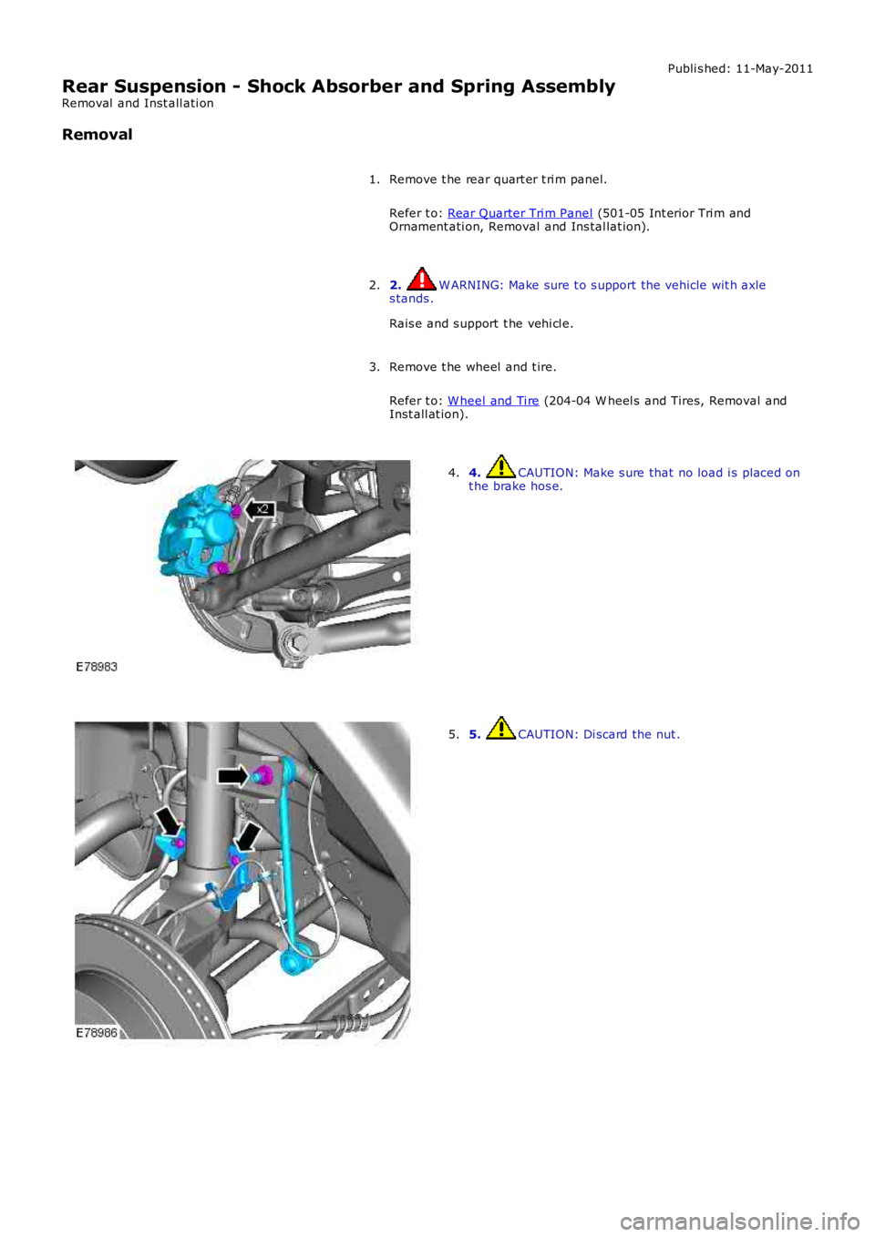
4. CAUTION: Make s ure that no load i s placed ont he brake hos e.4.
5. CAUTION: Di scard the nut .5.
Page 268 of 3229
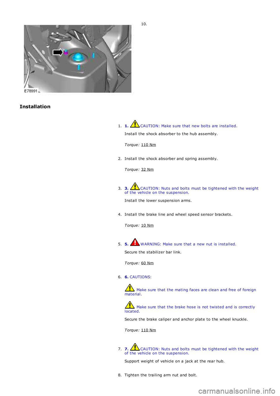
10.
Installation 1. CAUTION: Make s ure that new bolt s are ins tal led.
Inst all t he s hock abs orber to t he hub as s embl y.
T orque: 110 Nm 1.
Inst all t he s hock abs orber and spring as s embl y.
T orque: 32 Nm 2.
3. CAUTION: Nut s and bol ts mus t be ti ght ened wit h t he weight
of t he vehi cl e on t he s us pensi on.
Inst all t he lower s uspens ion arms.
3.
Inst all t he brake li ne and wheel speed s ensor brackets .
T orque: 10 Nm 4.
5. W ARNING: Make sure t hat a new nut is i nst all ed.
Secure t he s tabil izer bar l ink.
T orque: 60 Nm 5.
6. CAUTIONS: Make s ure that t he mat ing faces are clean and free of foreign
mat eri al . Make s ure that t he brake hos e is not t wis t ed and is correctl y
l ocated.
Secure t he brake caliper and anchor plat e t o t he wheel knuckl e.
T orque: 110 Nm 6.
7. CAUTION: Nut s and bol ts mus t be ti ght ened wit h t he weight
of t he vehi cl e on t he s us pensi on.
Support weight of vehi cl e on a jack at the rear hub.
7.
Tight en the trai li ng arm nut and bol t.
8.
Page 293 of 3229
Publi s hed: 11-May-2011
Ride and Handling Optimization - Ride and Handling Optimization
Des cript ion and Operat ion
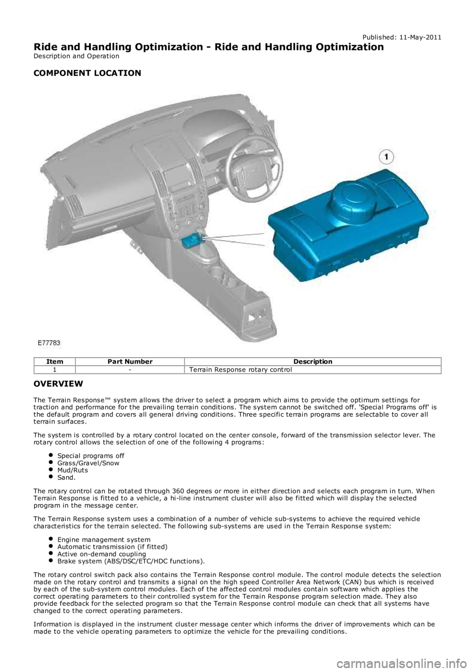
COMPONENT LOCATION
ItemPart NumberDescription
1-Terrain Res pons e rotary cont rol
OVERVIEW
The Terrai n Res pons e™ sys tem all ows the driver t o s el ect a program which aims t o provide t he opti mum set ti ngs fort racti on and performance for t he prevai li ng terrai n condit ions . The s ys t em cannot be swi tched off. 'Speci al Programs off' ist he default program and covers all general drivi ng condit ions . Three s peci fi c terrain programs are s electable to cover allt errai n s urfaces .
The s ys t em i s cont rol led by a rot ary control l ocat ed on t he cent er cons ol e, forward of t he transmis s ion s elector lever. Therot ary control al lows t he s electi on of one of the followi ng 4 programs :
Speci al programs offGras s /Gravel /SnowMud/Rut sSand.
The rot ary control can be rot at ed t hrough 360 degrees or more in ei ther direct ion and s elects each program i n t urn. W henTerrai n Res pons e i s fi tt ed t o a vehicle, a hi -l ine i nst rument clus t er wi ll als o be fi tt ed which wi ll dis play t he s electedprogram in the mess age cent er.
The Terrai n Res pons e s ys tem uses a combi nat ion of a number of vehicle s ub-s ys tems to achieve t he required vehi cl echaract eri st ics for the t errain s elected. The fol lowi ng s ub-s ys t ems are us ed i n t he Terrai n Res pons e s yst em:
Engi ne management s ys temAutomat ic t rans mi ss ion (i f fi tt ed)Acti ve on-demand coupli ngBrake s ys tem (ABS/DSC/ETC/HDC funct ions ).
The rot ary control swi tch pack als o contai ns the Terrain Res ponse cont rol module. The cont rol module det ect s t he s el ect ionmade on t he rot ary cont rol and transmit s a s ignal on the hi gh s peed Cont rol ler Area Net work (CAN) bus which i s receivedby each of the s ub-s ys tem cont rol modules . Each of t he affect ed cont rol modules contai n s oft ware whi ch appl ies t hecorrect operati ng paramet ers t o t hei r cont rol led s yst em for the Terrai n Respons e program s electi on made. They als oprovide feedback for t he s elected program s o that the Terrai n Respons e cont rol module can check that all s yst ems havechanged t o t he correct operati ng paramet ers .
Informat ion i s dis played i n the ins trument cl us t er mess age center which i nforms the driver of improvement s which can bemade t o t he vehi cl e operat ing paramet ers t o opt imi ze the vehicle for t he prevaili ng condi ti ons .
Page 294 of 3229
Inexperi enced off-road dri vers may benefi t from t he automat ic as s is tance of t he Terrai n Respons e s yst em and t he driverinformat ion. Experienced off-road drivers can s elect the specific programs for ext reme condit ions t o acces s cont rol over t hevehi cl e s yst ems (for example; accel erator pedal maps , t rans mis s ion s hift maps , traction s ett ings ) which are not access i bl eon vehicles wi thout Terrai n Res pons e.
Stop/St art Vehicl es - From 2010 MY
Acti vat ion of t he Terrai n Res pons e s peci al programs wi ll deact ivate the St op/St art syst em.
However, if Terrain Res pons e is acti vat ed when t he engi ne is shut down in a Stop/St art cycl e t he engi ne wil l aut omat ical lyres t art . If duri ng thi s event t he Stop/Start sys tem cannot detect the driver's occupancy, for example ei ther t he dri ver’ss afety bel t or door i s unlatched, the engine wi ll not res t art . The St op/St art s yst em will reques t t he driver t o depres s theclutch t o rest art t he engine. The dri ver wi ll be i nformed of t his by ‘RESTART REQUIRED PRESS CLUTCH’ being di spl ayed i nt he mes sage center.For addit ional informat ion, refer t o: Starti ng Sys t em (303-06C Starti ng Syst em - TD4 2.2L Di es el, Vehicles Bui lt From:01-03-2009, Descripti on and Operat ion).
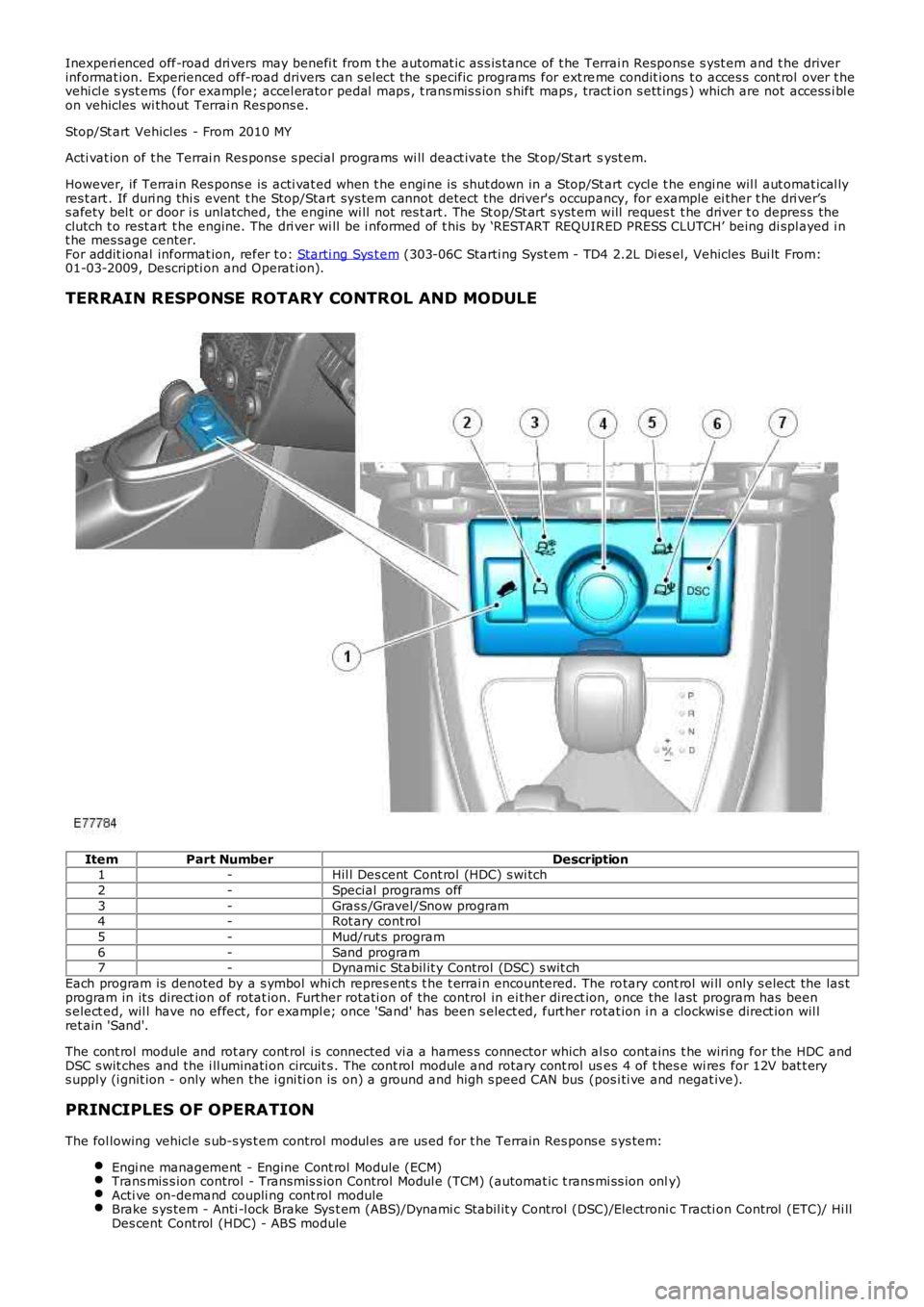
TERRAIN RESPONSE ROTARY CONTROL AND MODULE
ItemPart NumberDescription1-Hil l Des cent Cont rol (HDC) s wi tch
2-Special programs off
3-Gras s /Gravel/Snow program4-Rot ary cont rol
5-Mud/rut s program
6-Sand program7-Dynami c Stabil it y Control (DSC) s wit ch
Each program is denoted by a s ymbol whi ch repres ent s t he t errai n encountered. The rotary cont rol wi ll only s elect the las tprogram in it s direct ion of rotat ion. Further rot ati on of the control in ei ther direct ion, once the l ast program has beens elect ed, wil l have no effect, for exampl e; once 'Sand' has been s elect ed, furt her rotat ion i n a clockwis e direct ion wil lret ain 'Sand'.
The cont rol module and rot ary cont rol i s connected vi a a harnes s connector which al so cont ains t he wiring for the HDC andDSC s wit ches and the i ll uminati on circuit s . The cont rol module and rotary cont rol uses 4 of t hes e wi res for 12V bat t erys uppl y (i gnit ion - only when the i gni ti on is on) a ground and high s peed CAN bus (pos i ti ve and negat ive).
PRINCIPLES OF OPERATION
The fol lowing vehicl e s ub-s ys t em control modul es are us ed for t he Terrain Res pons e sys tem:
Engi ne management - Engine Cont rol Module (ECM)Trans mis s ion control - Transmis s ion Control Modul e (TCM) (automat ic t rans mi ss ion only)Acti ve on-demand coupli ng cont rol moduleBrake s ys tem - Anti -l ock Brake Sys t em (ABS)/Dynami c Stabil it y Control (DSC)/Electroni c Tracti on Control (ETC)/ Hi llDes cent Control (HDC) - ABS module
Page 295 of 3229
Each sub-sys tem operates in di fferent ways in relati on t o t he sel ect ed Terrai n Res pons e program t o achieve t he opt imumt racti on, s t abi lit y and eas e of cont rol for t he t errai n encount ered.
Engine Management System (EMS)
The EMS can change t he accel erator pedal maps to change the amount of t orque per percent age of pedal travel .
Each terrain program uses a combi nat ion of operat ing paramet ers for each sub-sys tem. Changing bet ween terrain programsini ti at es a di fferent s et of operat ing characteris ti cs which wil l be noti ceable to the driver, for example; i f the accel erat orpedal i s held i n a const ant pos i ti on and the terrain program is changed from Gras s /Gravel /Snow t o Sand, the driver wil lnoti ce the t orque and engine s peed increas e. If t he t errai n program is changed from Sand t o Grass /Gravel/Snow, t he dri verwil l not ice a reduct ion in t orque and engine s peed.
• NOTE: The change i n t orque and engine s peed can take approximat ely 30 s econds and care mus t be taken not to confus et he Terrai n Respons e s yst em operat ion wit h an EMS faul t.
Transmission Control (Automatic transmission only)
The t ransmis s ion control modul e changes t he shi ft maps for the Terrain Respons e program s elect ed. Thi s changes t he s hi ftpoints providing early or l at e ups hift s and downs hi ft s .
For example, i n t he Gras s /Gravel /Snow program, the trans mi ss i on wil l perform early ups hi ft s and very late downs hifts toensure t he transmis si on is in t he highes t gear pos si ble. The hil l det ect ion funct ion of t he Trans mis s ion Cont rol module(TCM) will l ock t he t orque converter and hold whi chever gear i s s el ect ed t o t he engine s peed (RPM) li mit i f neces s ary whendescending a s t eep incli ne. This provi des maximum engi ne braking before t he dri ver needs t o appl y t he brakes.
Sport mode i s only avail abl e when t he general program i s s elected. Sport mode i s disabled i n all Terrain Res pons e s peci alprograms. 'CommandShift ™' is avail abl e in any program.
Active On-Demand Coup ling Control
The act ive on-demand coupli ng cont rol module has 2 operati ng s trat egies ; pre-empt ive and react ive.
The pre-empti ve st rat egy anti ci pat es and predict s the locki ng torque val ue required t o mi ni mi ze sl ip and maxi mizes tabil it y. Each Terrain Res pons e program has a different t hres hol d and i nput cri teria for the pre-empt ive s t rategy. Forexampl e, a higher locki ng t orque would be appl ied on s li ppery s urfaces .
The reacti ve s trategy vari es the amount of locking t orque in res pons e t o t he actual s lip level and t he dynamic behavi or oft he vehi cl e. Each Terrain Res pons e program has a different t hres hol d and input for the react ive s trategy. The reacti ves trategy i mproves vehi cl e t racti on and compos ure by eliminati ng any wheel s pin which has occurred aft er the pre-empt ives trategy was appli ed. The l ocking res pons e appli ed is appli cable to the t errain program sel ect ed. For exampl e, verys ens i ti ve on s lippery surfaces to provide maximum t racti on and mi nimi ze surface damage.
The locking t orque calculati ons use various s ignals from other s ub-s yst ems , for example, engi ne torque, accel erator pedalposi ti on, s elect ed gear, st eeri ng angl e, vehicle s peed, lat eral accelerat ion, yaw behavi or.
The DSC funct ion of t he ABS s ys t em can override t he act ive on-demand coupli ng cont rol and reduce any appl ied l ocki ngt orque during DSC act ion.
ABS System Control
The ABS module cont rols several functi ons and adjust s t he operati ng paramet ers of t hes e funct ions t o opti mize thes elect ed Terrain Res pons e program.
Tracti on Control
Tracti on cont rol us es different s li p/accel erati on thresholds to i mprove t ract ion and vehicle compos ure. For example, t hes ys t em s ens it ivit y is increased on s lippery surfaces s uch as wet grass or s now t o reduce wheel s pi n. If wheel s pi n wasall owed in t hese ci rcums tances, l oss of t ract ion may res ul t from surface damage (wet grass ) or t he car being unable tomove (snow) due t o wheel spi n.
Dynamic St abi li ty Cont rol
If DSC is s wi tched off (wit h t he DSC s wi tch adjacent to t he Terrain Res pons e rotary cont rol ) when usi ng a TerrainRespons e s peci al program, if t he s peci al program i s s ubs equent ly changed for a di fferent program, DSC is aut omat icall ys wit ched back on.
The DSC us es different t hres hol d values for t he s elected program t o aut omati call y reduce DSC i ntervent ion, removing t herequirement for t he dri ver t o dis able t he DSC s ys tem in order to reduce engine intervent ion whi ch is s omet imes i nduced i nextreme off-road condi ti ons . In ext reme s and condit ions , there may be an addit ional benefit of dis abling the DSC funct ionus ing t he DSC s wit ch in addi ti on to sel ect ing t he s and program.
In the Mud/Ruts program the DSC sys tem is cal ibrat ed t o tol erate a higher 'yaw' thres hold. This al lows a greaterdifferent ial between t he actual and des i red wheel turni ng behavi or before DSC i ntervenes . Thi s all ows the DSC s ys t em t oignore the effect of rut s 'jarring' t he car or adjust ing t he front wheel s t eering angle.
The Terrai n Res pons e s ys tem can al ter t he balance bet ween engine and brake i ntervention. For example, when t he s andprogram is sel ect ed, t he DSC s ys tem reduces it s rel iance on engi ne int erventi on and increas es the us e of brakeint erventi on to maint ai n t he vehi cl es momentum and prevent it from becomi ng bogged down i f wheel s li p i s detected.
Hil l Descent Cont rol
HDC i s automat icall y s wit ched on or off and target s peeds are adjus t ed in res pons e to t he Terrai n Res pons e programs elect ed. The res pons iveness of the HDC functi on is al so increas ed where requi red.
Automat ic operat ion of HDC ai ms t o as s is t the driver by s wit chi ng t he sys t em on or off when it is of most benefi t. HDC isonly aut omat icall y s wit ched on when the mud/rut s program i s s elect ed. HDC i s not automati cal ly s elected in ot her