Page 616 of 3229
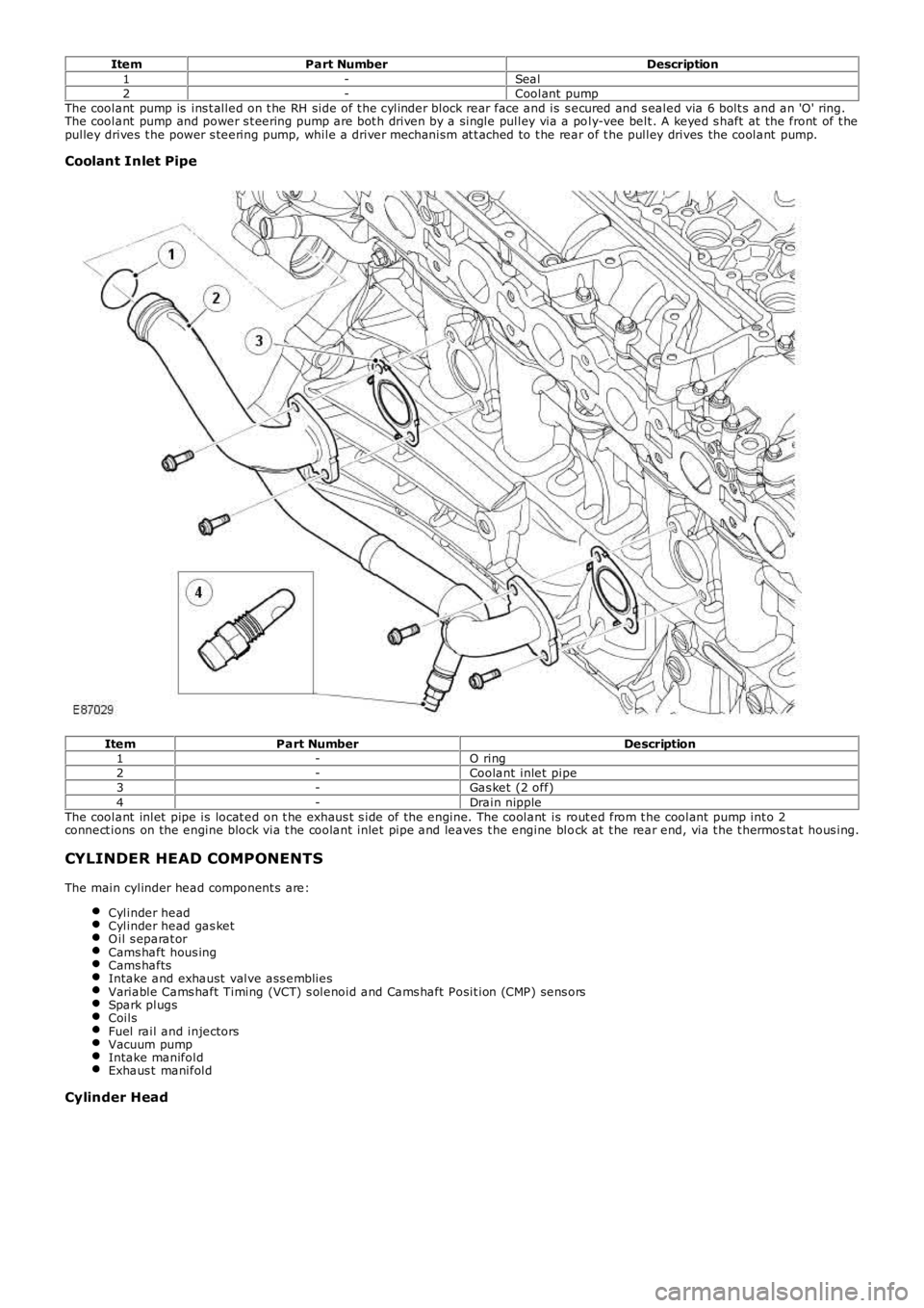
ItemPart NumberDescription1-Seal2-Coolant pumpThe coolant pump is ins t alled on t he RH side of t he cylinder block rear face and is s ecured and s ealed via 6 bolt s and an 'O' ring.The coolant pump and power s t eering pump are bot h driven by a single pulley via a poly-vee belt . A keyed s haft at the front of t hepulley drives t he power s teering pump, while a driver mechanism at t ached to t he rear of t he pulley drives the coolant pump.
Coolant Inlet Pipe
ItemPart NumberDescription1-O ring2-Coolant inlet pipe3-Gas ket (2 off)4-Drain nippleThe coolant inlet pipe is locat ed on t he exhaus t s ide of the engine. The coolant is rout ed from t he coolant pump int o 2connect ions on the engine block via t he coolant inlet pipe and leaves t he engine block at t he rear end, via t he t hermos tat hous ing.
CYLINDER HEAD COMPONENTS
The main cylinder head component s are:
Cylinder headCylinder head gas ketO il s eparat orCams haft hous ingCams haftsIntake and exhaust valve ass embliesVariable Cams haft Timing (VCT) s olenoid and Cams haft Posit ion (CMP) sens orsSpark plugsCoilsFuel rail and injectorsVacuum pumpIntake manifoldExhaus t manifold
Cylinder Head
Page 739 of 3229
Us ing s uit able t ools , rel eas e t he acces s ory drive beltt ens i on.17.
Releas e t he A/C and PAS li nes from t he clip.18.
Releas e t he A/C compress or and t ie as ide.19.
Page 752 of 3229
Publi s hed: 11-May-2011
Engine - TD4 2.2L Diesel -
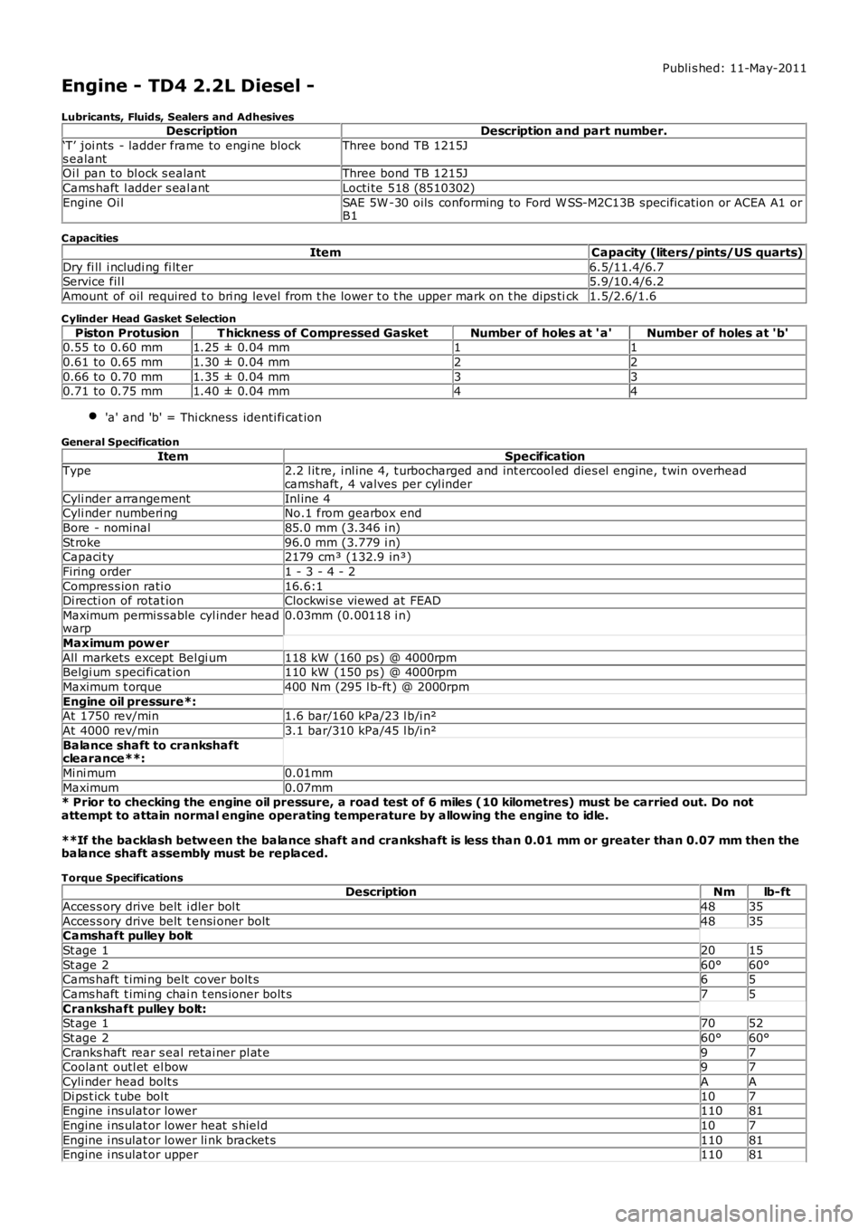
Lubricants, Fluids, Sealers and AdhesivesDescriptionDescription and part number.
‘T’ joi nts - ladder frame to engi ne blocks ealantThree bond TB 1215J
Oi l pan to bl ock s ealantThree bond TB 1215J
Cams haft l adder s eal antLocti te 518 (8510302)
Engine Oi lSAE 5W -30 oils conforming to Ford W SS-M2C13B specificat ion or ACEA A1 orB1
C apacities
ItemCapacity (liters/pints/US quarts)
Dry fi ll i ncludi ng fi lt er6.5/11.4/6.7Service fil l5.9/10.4/6.2
Amount of oil required t o bri ng level from t he lower t o t he upper mark on t he dips tick1.5/2.6/1.6
C ylinder Head Gasket Selection
Piston ProtusionT hickness of Compressed GasketNumber of holes at ' a'Number of holes at 'b'0.55 to 0.60 mm1.25 ± 0.04 mm11
0.61 to 0.65 mm1.30 ± 0.04 mm22
0.66 to 0.70 mm1.35 ± 0.04 mm330.71 to 0.75 mm1.40 ± 0.04 mm44
'a' and 'b' = Thi ckness identi fi cat ion
General Specification
ItemSpecificationType2.2 l it re, i nl ine 4, t urbocharged and int ercool ed dies el engine, t win overheadcamshaft , 4 valves per cyl inder
Cyli nder arrangementInl ine 4Cyli nder numberi ngNo.1 from gearbox end
Bore - nominal85.0 mm (3.346 i n)
St roke96.0 mm (3.779 i n)Capaci ty2179 cm³ (132.9 in³)
Firing order1 - 3 - 4 - 2
Compres s ion rati o16.6:1Di recti on of rotat ionClockwi s e viewed at FEAD
Maximum permi s sable cyl inder headwarp0.03mm (0.00118 i n)
Maximum pow er
All markets except Bel gi um118 kW (160 ps ) @ 4000rpmBelgi um s peci fi cat ion110 kW (150 ps ) @ 4000rpm
Maximum t orque400 Nm (295 l b-ft ) @ 2000rpm
Engine oil pressure*:At 1750 rev/min1.6 bar/160 kPa/23 l b/i n²
At 4000 rev/min3.1 bar/310 kPa/45 l b/i n²
Balance shaft to crankshaftclearance**:
Mi ni mum0.01mm
Maximum0.07mm* Prior to checking the engine oil pressure, a road test of 6 miles (10 kilometres) must be carried out. Do notattempt to attain normal engine operating temperature by allowing the engine to idle.
**If the backlash betw een the balance shaft and crankshaft is less than 0.01 mm or greater than 0.07 mm then thebalance shaft assembly must be replaced.
Torque SpecificationsDescriptionNmlb-ft
Acces s ory drive belt i dler bol t4835
Acces s ory drive belt t ensi oner bolt4835Camshaft pulley bolt
St age 12015
St age 260°60°Cams haft t imi ng belt cover bolt s65
Cams haft t imi ng chai n t ens ioner bolt s75
Crankshaft pulley bolt:St age 17052
St age 260°60°
Cranks haft rear s eal retai ner pl at e97Coolant outl et el bow97
Cyli nder head bolt sAA
Di ps t ick t ube bol t107Engine i ns ulat or lower11081
Engine i ns ulat or lower heat s hiel d107
Engine i ns ulat or lower li nk bracket s11081Engine i ns ulat or upper11081
Page 753 of 3229
DescriptionNmlb-ft
Engine mount bracket LH:
M8*2518M12*8059
Engine mount bracket RH:
M12*8059M14*175129
Engine mount LH bolt175129
Engine mount RH bol ts8059Flywheel bol tsAA
Fuel i njector wi ri ng harness bol t107
Fuel fil ter bracket bol ts2518Intake manifold runner control (IMRC) act uat or bol t107
Intake manifold adaptor and t hrot tl e hous i ng bol t65
Intake manifold bol ts97Lifti ng bracket s107
Oi l cooler brackets107
Oi l cooler t o cyl inder block bol ts2015Oi l fil ler t ube97
Oi l pan drain pl ug2015
Oi l pan bol ts97Oil pan extension panel:
St age 1107
St age 21612Oil pump bolts:97
St age 175
St age 297Oi l separat or bol ts75
Oi l level s ensor86
Pis t on cool ing jet bol t107Timing belt t ensi oner bolt2518
Timing belt i dler pulley bol t6044
Timing belt rear cover64Valve cover bol ts107
Vacuum pump bolt s97
* New nuts/bolts must be fitted
A = refer to procedure for correct torque sequence
Page 771 of 3229
Lateral movement of the cranks haft is res trict ed by 4 half-round thrus t was hers , located on bot h s ides of No. 2 mai nbearing. Lubricati on grooves are formed on t he thrus t was hers and mus t face toward the main beari ng. The cranks haftend-float mus t be bet ween 0.07 mm (0.003 in) and 0.32 mm (0.013 i n).
Each main beari ng housi ng and half cap cont ains an upper and lower bearing half s hell manufactured from al uminum/ti n.The upper half s hell s are formed wit h a dril li ng and annular groove t o t rans fer press uri zed oi l from t he main bearing,t hrough cranks haft drill ings t o t he connecti ng rod bi g-end bearings .
The main bearing half caps and t he upper and l ower beari ng half s hel ls are formed with a l ug. The l ug allows correctali gnment of t he bearing and cap, and prevent s radi al movement of t he bearing.
To mai nt ain the correct cranks haft mai n bearing cl earance, the main beari ng half s hells are avail abl e in varying t hicknes s .The upper mai n beari ng hal f s hel l is only avail abl e i n 1 s ize; t he lower mai n bearing hal f shell i s avai lable in 5 si zes . Bot ht he upper and lower mai n bearing hal f shel ls are col or coded for i dent ificati on. To det ermi ne t he correct s ize of bearing hal fs hel l, clas s ificat ion markings on t he cranks haft front face and on t he cyl inder bl ock front face are us ed in conjunct ion wi tha beari ng s ize chart .
For furt her det ail s on main bearing half s hell i ns t allat ion, refer to the relevant Servi ce Repai r Procedures (SRP).
A drive gear is formed as a 's hri nk-fit ' on No. 3 cranks haft web, located bet ween No. 2 mai n bearing journal and No. 2connecti ng rod bi g-end journal . The dri ve gear i s s ingle hel ical cut and provides t he dri ve to the counter-balance s haftgears . An 18 t eet h s pur gear i s located on the front of the cranks haft , behi nd the front cranks haft s eal ing pl at e. The s purgear provi des the drive t o t he oil pump as s embly via a s ingle row chain, and i s locked to the cranks haft wit h a woodruffkey.
A t oothed gear mount ed t o t he front of t he cranks haft provides t he dri ve for t he cams haft t iming belt . The dri ve gearcont ains 21 t eeth and is keyed to the cranks haft wit h a woodruff key.
Crankshaft Oil Seals
Page 776 of 3229
ItemPart NumberDescription
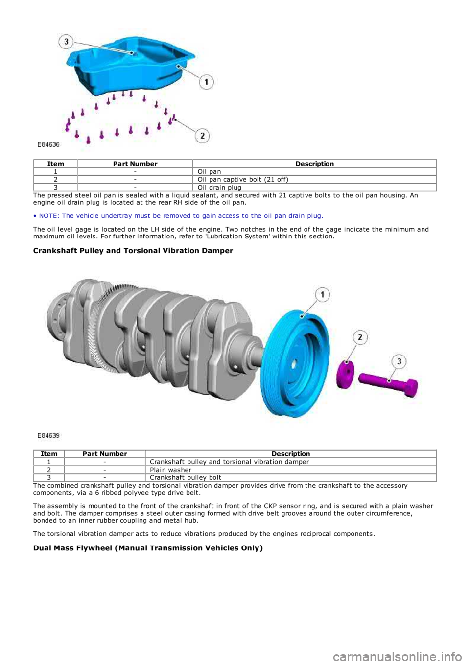
1-Oil pan2-Oil pan capti ve bol t (21 off)
3-Oil drai n plug
The pres s ed s teel oil pan is sealed wit h a l iquid sealant , and secured wi th 21 capt ive bolt s t o t he oil pan housi ng. Anengi ne oil drai n plug is l ocat ed at the rear RH s ide of t he oil pan.
• NOTE: The vehi cle undert ray mus t be removed to gai n acces s t o t he oil pan drain plug.
The oil l evel gage is l ocat ed on t he LH s ide of t he engi ne. Two not ches in t he end of t he gage indicate t he mi nimum andmaximum oil l evels . For further informat ion, refer t o 'Lubricat ion Sys t em' wit hi n t his s ect ion.
Crankshaft Pulley and Torsional Vibration Damper
ItemPart NumberDescription
1-Cranks haft pull ey and torsi onal vibrat ion damper
2-Plai n was her3-Cranks haft pull ey bol t
The combined crankshaft pul ley and t ors ional vi brat ion damper provides dri ve from t he crankshaft to the acces s orycomponents , via a 6 ribbed polyvee type drive belt .
The as sembl y is mount ed t o t he front of t he crankshaft in front of t he CKP s ens or ring, and i s s ecured wit h a pl ain was herand bolt . The damper compri ses a s teel out er cas i ng formed wit h drive belt grooves around t he outer circumference,bonded t o an inner rubber coupl ing and metal hub.
The t ors ional vi brati on damper act s to reduce vibrat ions produced by the engines reci procal component s .
Dual Mass Flywheel (Manual Transmission Vehicles Only)
Page 778 of 3229
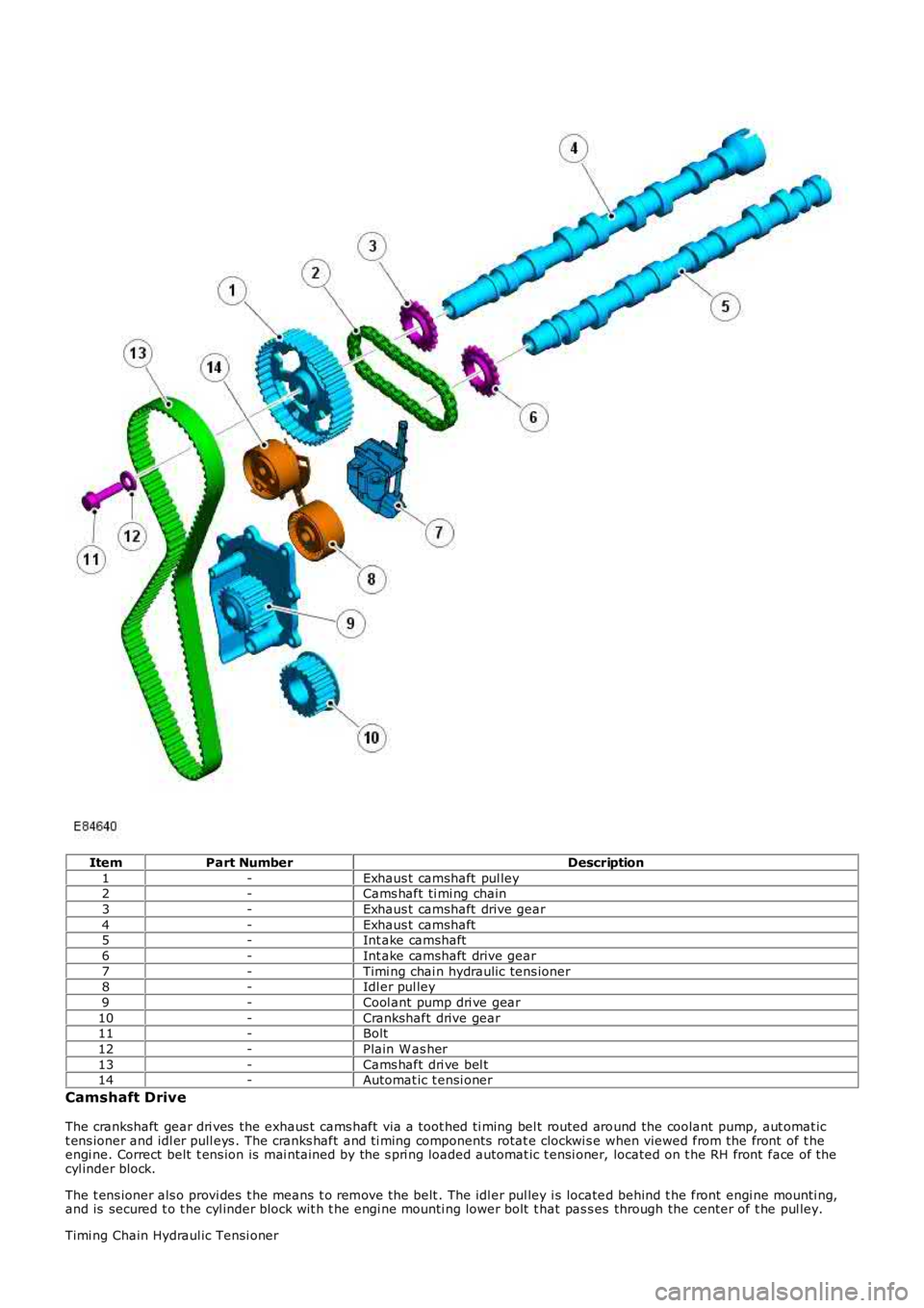
ItemPart NumberDescription
1-Exhaus t camshaft pul ley2-Cams haft ti mi ng chain
3-Exhaus t camshaft drive gear
4-Exhaus t camshaft5-Int ake camshaft
6-Int ake camshaft drive gear
7-Timi ng chai n hydraulic tens ioner8-Idl er pul ley
9-Cool ant pump dri ve gear
10-Crankshaft drive gear11-Bolt
12-Plain W as her
13-Cams haft dri ve bel t14-Automat ic t ensi oner
Camshaft Drive
The crankshaft gear dri ves the exhaus t cams haft via a toot hed ti ming bel t routed around the coolant pump, aut omat ict ens ioner and idl er pull eys . The cranks haft and ti ming components rotat e clockwi s e when viewed from the front of t heengi ne. Correct belt t ens ion is mai ntained by the s pri ng loaded automat ic t ensi oner, located on t he RH front face of thecyl inder block.
The t ens ioner als o provi des t he means t o remove the belt . The idl er pul ley i s located behind t he front engi ne mounti ng,and is secured t o t he cyl inder block wit h t he engi ne mounti ng lower bolt t hat pas s es through the center of t he pul ley.
Timi ng Chain Hydraul ic Tensi oner
Page 781 of 3229
ItemPart NumberDescription
1-Rear ti ming belt cover2-Upper t iming belt cover
3-Lower t iming belt cover
4-Screw (9 off)A 1-piece rear and 2-pi ece front t iming belt cover enclos es the cams haft drive component s. The pl as t ic t iming covers ares ecured to the cyli nder block and cylinder head wit h 9 s crews . A hol e is formed in the upper front t iming belt cover, and isprovided t o all ow t he ins ert ion of a special t ool us ed to lock t he exhaus t cams haft pull ey.
CYLINDER HEAD COMPONENTS