2006 LAND ROVER FRELANDER 2 belt
[x] Cancel search: beltPage 540 of 3229
diamet er in i ts central sect ion. The smal ler diamet er allows the t ors ion bar t o t wist in res pons e t o t orque appli ed from t hes teeri ng wheel in relati on t o t he grip of the t yres on t he road surface. The pi nion s haft has machined t eet h on it s cent raldiamet er whi ch mat e wit h t eeth on the s t eering gear rack. A s lot , machi ned in t he upper end of t he pini on s haft mateswit h t he dog-t oot h on the i nput s haft . The pinion s haft l ocat es in the pi ni on housi ng and rot ates on bal l and roll erbearings .
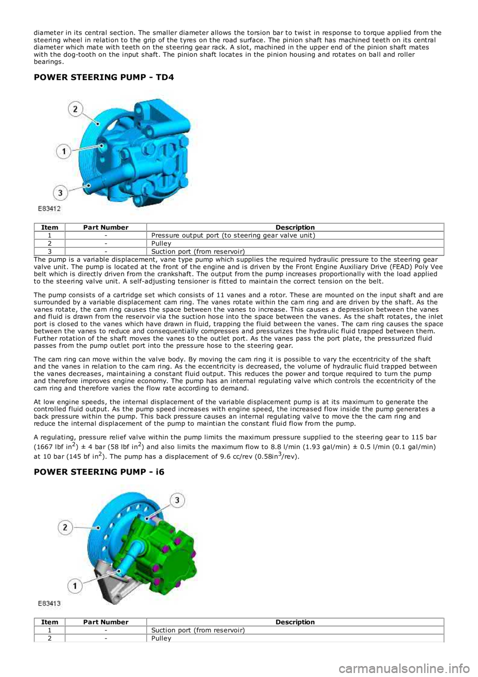
POWER STEERING PUMP - TD4
ItemPart NumberDescription1-Pres s ure out put port (t o s t eering gear val ve unit )
2-Pull ey
3-Sucti on port (from res ervoi r)The pump i s a vari abl e dis placement, vane t ype pump which s uppl ies t he required hydraulic pres sure t o the st eeri ng gearvalve unit . The pump is locat ed at t he front of t he engine and i s dri ven by the Front Engine Auxil iary Dri ve (FEAD) Poly Veebelt which i s direct ly driven from the cranks haft . The out put from t he pump i ncreas es proporti onall y wi th the l oad appl iedt o the st eeri ng val ve uni t. A s el f-adjus ti ng tens ioner is fit t ed to maint ai n t he correct t ens ion on the bel t.
The pump consi st s of a cart ridge s et which cons is t s of 11 vanes and a rot or. These are mount ed on t he input s haft and ares urrounded by a variable di spl acement cam ring. The vanes rotat e wit hin the cam ri ng and are driven by t he s haft. As thevanes rotat e, the cam ri ng caus es the space between t he vanes to increase. This causes a depres si on between t he vanesand fl uid i s drawn from t he res ervoir vi a t he suct ion hos e int o t he s pace between the vanes. As t he s haft rotat es , t he inl etport i s clos ed to the vanes which have drawn in fluid, t rapping t he fluid bet ween t he vanes . The cam ring caus es t he s pacebetween t he vanes to reduce and cons equenti ally compress es and pres s uri zes t he hydrauli c fl ui d t rapped between t hem.Furt her rotat ion of t he s haft moves the vanes t o the out let port . As t he vanes pas s t he port plat e, the pres s uri zed fl ui dpass es from the pump out let port into the press ure hose to the s t eering gear.
The cam ring can move wi thi n t he val ve body. By moving the cam ri ng it i s poss ibl e to vary t he eccentricit y of t he s haftand t he vanes i n rel ati on to the cam ri ng. As t he eccent rici ty i s decreased, t he volume of hydraulic flui d t rapped bet weent he vanes decreases , mai nt aining a cons t ant flui d output. This reduces t he power and torque required to turn t he pumpand t herefore improves engine economy. The pump has an int ernal regulati ng valve which controls t he eccentricit y of t hecam ring and t herefore vari es the flow rat e accordi ng to demand.
At low engi ne s peeds , the i nternal dis placement of the vari able di spl acement pump i s at it s maximum t o generate thecont rol led fluid out put. As t he pump s peed increas es wit h engine s peed, t he i ncreas ed flow ins ide t he pump generates aback press ure wit hin the pump. This back pres s ure causes an internal regul ati ng val ve to move t he the cam ri ng andreduce t he int ernal di spl acement of the pump to maint ian t he cons t ant flui d fl ow from the pump.
A regul ati ng, pres s ure reli ef val ve wit hin t he pump l imi ts the maxi mum press ure s uppl ied t o t he s teeri ng gear t o 115 bar
(1667 l bf in2) ± 4 bar (58 lbf i n2) and al so li mit s t he maximum fl ow t o 8.8 l/min (1.93 gal/min) ± 0.5 l /min (0.1 gal /min)
at 10 bar (145 bf i n2). The pump has a dis placement of 9.6 cc/rev (0.58i n3/rev).
POWER STEERING PUMP - i6
ItemPart NumberDescription
1-Sucti on port (from res ervoi r)
2-Pull ey
Page 551 of 3229
Refer t o:
Air Cleaner (303-12A Intake Ai r Dis tribut ion and Fil tering -
I6 3.2L Pet rol, Removal and Ins t al lat ion).
3. CAUTION: Di scard fl ui d s iphoned from t he power st eeri ng
s yst em.
Siphon t he fl uid from t he power s t eering res ervoi r.
3.
Pos it ion an abs orbent cl oth t o coll ect fluid s pi ll age.
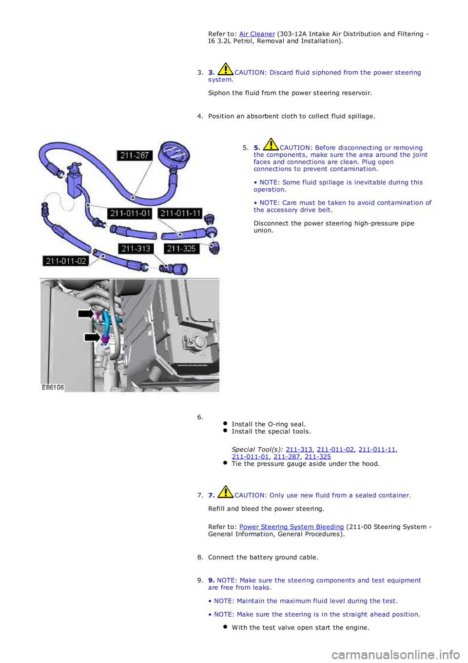
4. 5. CAUTION: Before di s connect ing or removi ng
the component s , make s ure t he area around the joint
faces and connect ions are clean. Pl ug open
connect ions t o prevent cont aminat ion.
• NOTE: Some fluid spi llage i s inevit able duri ng t hi s
operati on.
• NOTE: Care mus t be t aken to avoi d cont aminat ion of
the acces s ory drive belt .
Dis connect the power s teeri ng high-press ure pipe
uni on.
5.
Inst all t he O-ring seal. Inst all t he s pecial t ool s.
Speci al Tool (s ): 211-313 ,
211-011-02 ,
211-011-11 ,
211-011-01 ,
211-287 ,
211-325 Tie the press ure gauge as ide under t he hood.6.
7. CAUTION: Only use new fl uid from a s ealed container.
Refi ll and bleed t he power st eeri ng.
Refer t o: Power St eering Sys tem Bleeding (211-00 St eering Sys tem -
General Informat ion, General Procedures ).
7.
Connect t he batt ery ground cable.
8.
9. NOTE: Make s ure t he s teeri ng component s and tes t equipment
are free from leaks .
• NOTE: Mai nt ain the maxi mum flui d level during t he t est .
• NOTE: Make s ure the s t eering i s i n the st rai ght ahead pos it ion. W it h the tes t val ve open s tart the engine. 9.
Page 554 of 3229
Publi s hed: 11-May-2011
Power Steering - Power Steering PumpI6 3.2L Petrol
Removal and Inst all ati on
Removal
Remove t he cover and dis connect the bat tery ground cabl e.
Refer t o: Specificati ons (414-00 Bat tery and Charging Sys tem -General Informat ion, Specificati ons).
1.
Remove t he engi ne cover.
Refer t o: Engi ne Cover - I6 3.2L Pet rol (501-05 Int eri or Trim andOrnament ati on, Removal and Ins tal lat ion).
2.
Remove t he bat t ery t ray.
Refer t o: Bat t ery Tray (414-01 Bat tery, Mount ing and Cables ,Removal and Ins tall ati on).
3.
Remove t he air cleaner as s embly.
Refer t o: Air Cleaner (303-12A Intake Ai r Dis tribut ion and Fil tering -I6 3.2L Pet rol, Removal and Ins t al lat ion).
4.
Siphon t he fl uid from t he power s t eering res ervoi r.5.
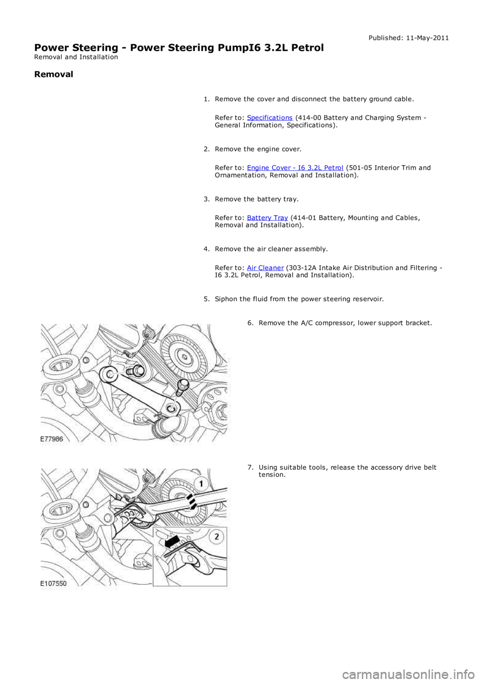
Remove t he A/C compress or, l ower support bracket.6.
Us ing s uit able t ools , rel eas e t he acces s ory drive beltt ens i on.7.
Page 557 of 3229
Publi s hed: 11-May-2011
Power Steering - Power Steering PumpTD4 2.2L Diesel
Removal and Inst all ati on
Removal
CAUTION: Always pl ug any open connect ions t o prevent cont aminati on.
Remove t he engi ne cover.
Refer t o: Engi ne Cover - TD4 2.2L Dies el (501-05 Interior Tri m andOrnament ati on, Removal and Ins tal lat ion).
1.
Remove t he acces sory dri ve bel t.
Refer t o: Acces sory Dri ve Belt (303-05B Acces sory Drive - TD4 2.2LDi es el, Removal and Ins tal lat ion).
2.
3. W ARNING: Power s t eering fluid is ext remely fl ammable.Make s ure that power s t eering flui d is not s pil t over t he engine andt hat t he power s teeri ng fl uid reservoi r cap is s ealed.
Siphon t he fl uid from t he power s t eering res ervoi r.
3.
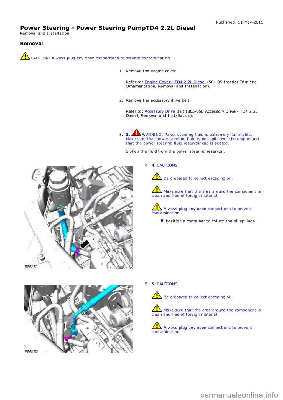
4. CAUTIONS:
Be prepared t o collect es caping oi l.
Make s ure that t he area around the component i sclean and free of foreign materi al.
Al ways pl ug any open connect ions t o preventcont ami nat ion.
Pos it ion a contai ner t o coll ect t he oil s pill age.
4.
5. CAUTIONS:
Be prepared t o collect es caping oi l.
Make s ure that t he area around the component i sclean and free of foreign materi al.
Al ways pl ug any open connect ions t o preventcont ami nat ion.
5.
Page 559 of 3229
Refer t o: Acces sory Dri ve Belt (303-05B Acces sory Drive - TD4 2.2LDi es el, Removal and Ins tal lat ion).
Inst all t he engi ne cover.
Refer t o: Engi ne Cover - TD4 2.2L Dies el (501-05 Interior Tri m andOrnament ati on, Removal and Ins tal lat ion).
6.
Fil l and bl eed the power s t eering s ys tem.
Refer t o: Power St eering Sys tem Bleeding (211-00 St eering Sys tem -General Informat ion, General Procedures ).
7.
Page 573 of 3229
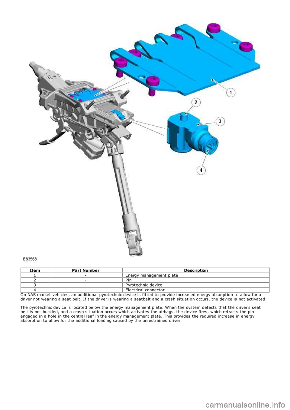
ItemPart NumberDescription
1-Energy management plate2-Pin
3-Pyrot echnic device
4-Elect rical connectorOn NAS market vehi cl es, an addit ional pyrotechnic device is fi tt ed to provide i ncreas ed energy abs orpt ion t o all ow for adri ver not weari ng a s eat bel t. If t he driver is wearing a s eat belt and a cras h s i tuati on occurs, t he devi ce is not acti vat ed.
The pyrotechnic device is locat ed below the energy management plat e. W hen the sys tem detects that t he driver's s eatbelt i s not buckled, and a cras h s it uati on occurs whi ch act ivates the ai rbags, t he devi ce fi res , which retract s t he pinengaged i n a hole in the central l eaf in t he energy management pl ate. This provi des the requi red i ncrease in energyabsorpti on to al low for t he addi ti onal l oading caus ed by t he unrest rai ned dri ver.
Page 585 of 3229

Publi s hed: 11-May-2011
Steering Column Switches - Steering Column Switches
Des cript ion and Operat ion
COMPONENT LOCATION
ItemPart NumberDescription
1-Speed cont rol s wit ches2-St eering column cas e containi ng the mult ifunct ion s wit ches and cl ocks pring
3-Audio control swit ches
OVERVIEW
The winds hield wiper s wit ch is l ocat ed in the right -hand-s ide of t he cas e and retai ned wit h 2 s crews . The s wit ch isconnected t o t he mai n harness vi a a connect or at the back of the s wi tch. The s wit ch cont rols the followi ng functi ons :
W i nds hiel d wi per i nt ermit tent s low and fas t speedW i nds hiel d wi per fli ck wipeW i nds hiel d was h/wi peRear was h/wipeInt ermit tent delay s electi on.
The t urn s ignal indicator s wit ch is locat ed i n t he left -hand-si de of the cas e and ret ained wi th 2 s crews . The swi tch i sconnected t o t he mai n harness vi a a connect or on the back of t he swit ch. The s wit ch cont rol s the foll owing funct ions:
Left / right turn s ignal operati onHigh / low beam operati onHeadl amp flas hTri p comput er functi on s el ect ion (i f fit t ed).
The t rip but t on allows the driver to cycle t hough an opti on menu and als o reset t ri p cycl e mi leage cal cul ati ons . The t ripcomput er informat ion i s dis played in the i nst rument clus ter mes s age cent er (high line ins trument cl us t er onl y).
Steering wheel mount ed s wit ches on the right -hand-s ide of t he dri ver's ai rbag, cont rol the audi o and tel ephone funct ions.Swit ches on the l eft -hand-s ide of t he dri ver's ai rbag control t he s peed cont rol functi ons .
The clocks pri ng is locat ed i n the front of t he cas e and retai ned wit h four s crews . The clocks pri ng engages i n s lots in t hes teeri ng wheel bos s and t urns wi th the rotat ion of t he s teeri ng wheel. The clocks pring incorporat es a t ang which cancelst he turn s ignal indicators when the st eering wheel i s rot ated.For addit ional informat ion, refer t o: Air Bag and Safet y Belt Pretens ioner Supplement al Res traint Syst em (SRS) (501-20BSuppl ement al Rest rai nt Sys tem, Des cri pti on and Operati on).
CONTROL DIAGRAM
• NOTE: A = Hardwi red; D = Hi gh s peed CAN bus , O = LIN bus
Page 613 of 3229
The intermediat e s haft is us ed to locat e the cams haft drive s haft gear wheel in t he cylinder block. The shaft is journaled wit h adouble conical roller bearing. The auxiliary unit s haft drive gear wheel is in 2 pieces , wit h t he narrow half being s pring tensioned inthe opposit e direct ion t o t he wide half. This feat ure reduces nois e becaus e gear play is eliminat ed. Only t he wide half drives theauxiliary unit's gear wheel. The cams haft chain gear wheel is of t he conventional design.
The s haft is sealed against the exhaust side (i.e. the rear s ide of t he cylinder block) by a s ealing was her. To remove or inst all t hewasher, t he flywheel/flexplate must be removed.
Camshaft Drive O uter Shaft
The cams haft drive outer s haft is journaled at the front end of t he s haft with a double row bearing in t he gear hous ing. Needlebearings are us ed at t he rear end (pulley s ide) against t he auxiliary unit s haft . The camshaft drive out er s haft gear wheel is in 2pieces , a wide and a narrow half t o reduce nois e. The cams haft chain gear wheel is als o locat ed on the s haft and is us ed to drivethe cams hafts chain.
Auxiliary Unit Inner Shaft
The auxiliary unit inner s haft is journaled at t he front end of t he shaft (generator s ide) in t he gear housing with a s ingle rowbearing. Needle bearings are used at the rear end (pulley s ide) against the cams haft drive shaft . There is a pulley at t he rear endof the s haft that drives t he Air Condit ioning (AC) compress or and the power s t eering pump, via a polyvee belt . The shaft als odrives t he generat or at t he front end, via a sleeve connect or.
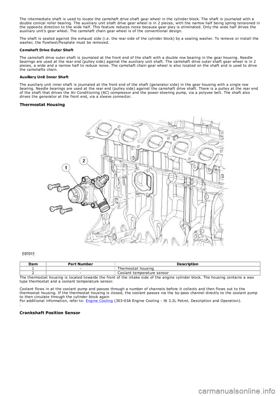
Thermostat Housing
ItemPart NumberDescription1-Thermost at hous ing2-Coolant t emperat ure s ens orThe t hermos tat hous ing is located t owards the front of t he int ake s ide of t he engine cylinder block. The hous ing contains a waxtype t hermost at and a coolant temperat ure sens or.
Coolant flows in at t he coolant pump and pas s es through a number of channels before it collect s and t hen flows out t o t hethermos t at housing. If t he t hermost at hous ing is closed, t he coolant pass es via t he by-pass channel directly to t he coolant pumpto then circulat e t hrough t he cylinder block againFor addit ional information, refer t o: Engine Cooling (303-03A Engine Cooling - I6 3.2L Pet rol, Des cription and Operat ion)..
Crankshaft Position Sensor