2006 LAND ROVER FRELANDER 2 belt
[x] Cancel search: beltPage 185 of 3229
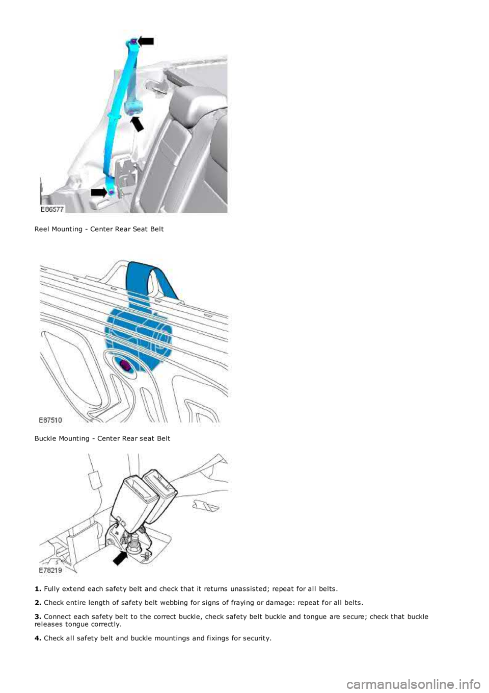
Reel Mount ing - Center Rear Seat Bel t
Buckl e Mount ing - Cent er Rear s eat Belt
1.
Ful ly ext end each s afet y belt and check that it returns unas s is ted; repeat for al l bel ts .
2. Check ent ire length of safet y belt webbing for s igns of frayi ng or damage: repeat f or al l bel ts .
3. Connect each safet y belt t o t he correct buckl e, check s afety bel t buckle and tongue are s ecure; check t hat buckle
rel eas es t ongue correct ly.
4. Check al l safet y belt and buckle mount ings and fi xings for s ecurit y.
Page 186 of 3229
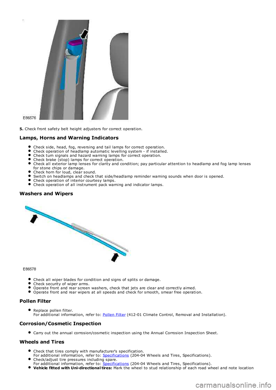
5.
Check front s afet y belt height adjus ters for correct operat ion.
Lamps, Horns and Warning Indicators Check s i de, head, fog, revers ing and tail l amps for correct operat ion. Check operat ion of headlamp aut omati c levelli ng s yst em - if ins t al led.
Check t urn si gnal s and hazard warni ng lamps for correct operati on.
Check brake (s t op) l amps for correct operat ion.
Check al l ext eri or l amp l ens es for cl arit y and condi ti on; pay parti cular at tent ion t
o headl amp and fog lamp lens es
for s t one chi ps or damage. Check horn for l oud, clear s ound.
Swit ch on headl amps and check t hat si de/headl amp reminder warning s ounds when door i
s opened.Check operat ion of i nteri or courtes y lamps .
Check operat ion of al l i nst rument pack warni ng and indicator l amps.
Washers and Wipers
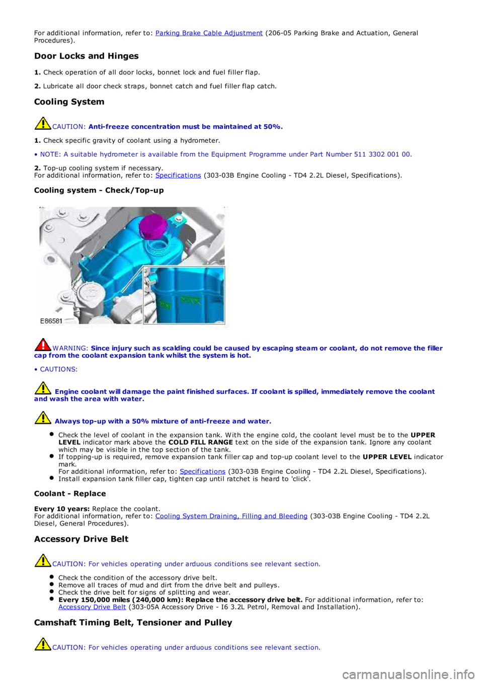
Check al l wiper blades for condi ti on and s igns of s pl it s or damage.
Check s ecurit y of wi per arms .
Operat e front and rear s creen washers, check that jet s are cl ear and correctl y aimed
.Operat e front and rear wipers at all s peeds and check for s moot h, s mear free operati
on.Pollen Filter
Replace pol len fil ter.
For addit ional informat ion, refer t o: Pollen Fi lt er (412-01 Cl imat e Control, Removal and Ins tall ati on).
Corrosion/Cosmetic Inspection
Carry out the annual corros ion/cos meti c ins pect ion us ing t he Annual Corros ion Inspec ti on Sheet .Wheels and Tires
Check t hat ti res comply wit h manufacturer's specificati on.
For addit ional informat ion, refer t o: Specificati ons (204-04 W heels and Tires , Specificati ons ).
Check/adjust t ire pres s ures i ncl udi ng s pare.
For addit ional informat ion, refer t o: Specificati ons (204-04 W heels and Tires , Specificati ons ).
Vehicle fitted with Uni-directional tires:
Mark t he wheel to st ud rel ati ons hip of each road wheel and note locat ion
Page 188 of 3229
For addit ional informat ion, refer t o: Parking Brake Cabl e Adjus tment (206-05 Parki ng Brake and Actuat ion, General
Procedures).
Door Locks and Hinges
1. Check operat ion of all door locks, bonnet lock and fuel fi ll er flap.
2. Lubricate al l door check s t raps , bonnet cat ch and fuel fill er fl ap cat ch.
Cooling System CAUTION:
Anti-freeze concentration must be maintained at 50%.
1. Check s peci fi c gravit y of cool ant us ing a hydrometer.
• NOTE: A s uit able hydromet er is avail abl e from the Equipment Programme under Part N umber 511 3302 001 00.
2. Top-up cool ing s ys tem if neces s ary.
For addit ional informat ion, refer t o: Specificati ons (303-03B Engine Cool ing - TD4 2.2L Dies el, Speci fi cat ions ).
Cooling system - Check/Top-up W ARNING:
Since injury such as scalding could be caused by escaping steam or coolant, do not r emove the filler
cap from the coolant expansion tank whilst the system is hot.
• CAUTIO NS:
Engine coolant w ill damage the paint finished surfaces. If coolant is spilled, immed iately remove the coolant
and wash the area with water.
Always top-up with a 50% mixture of anti-freeze and water.
Check t he l evel of cool ant i n t he expans ion t ank. W it h t he engi ne col d, the coolant level must be to the UPPER
LEVEL indicat or mark above the COLD FILL RANGE t ext on the s i de of the expans i on tank. Ignore any coolant
which may be vis ible in t he t op s ect ion of t he t ank. If topping-up i s requi red, remove expans ion tank fill er cap and top-up coolant level
to the UPPER LEVEL indicat or
mark.
For addit ional informat ion, refer t o: Specificati ons (303-03B Engine Cool ing - TD4 2.2L Dies el, Speci fi cat ions ).
Ins t all expans ion t ank fi ll er cap, ti ght en cap unti l ratchet is heard to 'cli ck'.
Coolant - Replace
Every 10 years: Repl ace the coolant.
For addit ional informat ion, refer t o: Cool ing Sys tem Drai ning, Fi ll ing and Bl eeding (303-03B Engine Cooli ng - TD4 2.2L
Dies el, General Procedures).
Accessory Drive Belt CAUTION: For vehi cl es operati ng under arduous condi ti ons s ee relevant s ecti on.
Check t he condi ti on of the access ory drive bel t. Remove all t races of mud and dirt from t he dri ve belt and pull eys .
Check t he drive belt for si gns of s pli tt ing and wear.
Every 150,000 miles (240,000 km): Replace the accessory drive belt.
For addit ional i nformati on, refer t o:
Acces s ory Drive Belt (303-05A Acces s ory Drive - I6 3.2L Pet rol , Removal and Ins t allat ion).
Camshaft Timing Belt, Tensioner and Pulley
CAUTION: For vehi cl es operati ng under arduous condi ti ons s ee relevant s ecti on.
Page 189 of 3229
1. Every 10 years or 150,000 miles (240,000 km): Repl ace the cams haft t imi ng belt , tens ioner and pul ley.
For addit ional informat ion, refer t o:
Timi ng Belt (303-01B Engi ne - TD4 2.2L Dies el, Removal and Inst all ati on).
Fluid levels
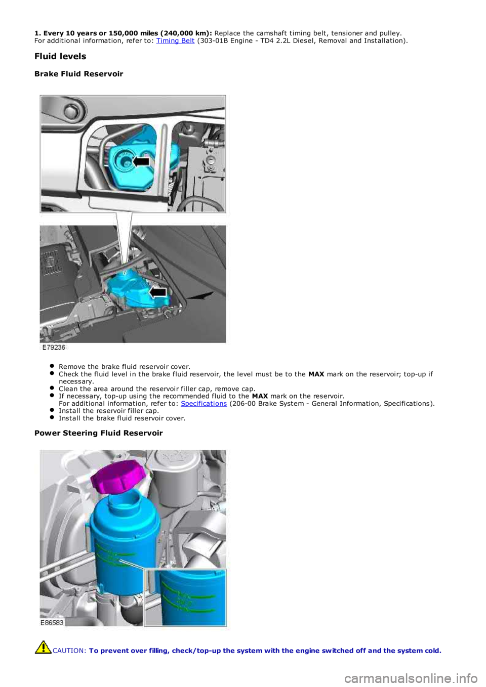
Brake Fluid Reservoir Remove the brake fl uid reservoi r cover.
Check t he fluid level i n t he brake fluid res ervoir, the l evel mus t be t o t he
MAX mark on the reservoi r; t op-up i f
neces s ary. Clean t he area around the res ervoi r fi ll er cap, remove cap.
If necess ary, t op-up us ing t he recommended fluid to the
MAX mark on t he res ervoir.
For addit ional informat ion, refer t o: Specificati ons (206-00 Brake Syst em - General Informati on, Speci fi cat ions ).
Ins t all the res ervoir fill er cap.
Ins t all the brake fl uid reservoi r cover.
Power Steering Fluid Reservoir
CAUTION:
T o prevent over filling, check/top-up the system with the engine sw itched off and th e system cold.
Page 192 of 3229
Ins pect rear pads for wear.
Check brake cal ipers for s igns of fl ui d l eaks .
Check brake dis cs for condi ti on.
Check al l brake boos t er and brake s ys t em pipes and hos es for condi ti on, chafi ng and
leaks.Clean road wheel hub s pigot s and appl y greas e, Land Rover Part Number RY L 105020 t o
t he wheel mat ing surface
of each s pigot . Brake Fluid Replacement
CAUTION:
When vehicles are operating under arduous conditions, the following service item mus t be carried out
every 2 Years or 30,000 miles (48,000 km).
Replace brake fluid. Road Wheel Speed Sensors
CAUTION:
When vehicles are operating under arduous conditions, the following service item mus t be carried out
every 3 months or 3,750 miles (6,000 km).
Ins pect the road wheel s peed s ens or harness es for damage. Engine Oil and Filter
• CAUTIO NS:
When vehicles are operating under arduous conditions, the following service item mus t be carried out every 3
months or 3,750 miles (6,000 km).
Vehicles operating on high sulphur content fuel - above 0.7%, the oil and filter cha nge period MUST NOT
exceed 3 months or 3,750 miles (6,000 km).
Vehicles operating on moderate sulphur content fuel - 0.3 to 0.7%, the oil and filte r change period MUST NOT
exceed 6 months or 7,500 miles (12,000 km).
Renew engi ne oil and fil ter. Air Filtering
CAUTION:
When vehicles are operating under arduous conditions, the following service item mus t be carried out
every 12 months or 15,000 miles (24,000 km).
Replace the ai r fi lt er el ement.
For addit ional informat ion, refer t o: Air Cl eaner (303-12A Int ake Ai r Dis t ri but ion and Fi lt ering - I6 3.2L Petrol ,
Removal and Inst all ati on). Accessory Drive Belt
CAUTION:
When vehicles are operating under arduous conditions, the following service item mus t be carried out
every 5 years or 75,000 miles (120,000 km).
Replace the access ory drive bel t. For addi ti onal informat ion, refer to: Acces s ory Drive Belt (303-05A Acces s ory Drive
- I6 3.2L Pet rol, Removal and Ins tal lat ion). Camshaft Timing Belt, Tensioner and Pulley
CAUTION:
When vehicles are operating under arduous conditions, the following service item mus t be carried out
every 4 years or 60,000 miles (96,000 km).
Replace the cams haft t iming belt , tens ioner and pul ley.
For addit ional informat ion, refer t o: Timi ng Belt (303-01B Engi ne - TD4 2.2L Dies el, Removal and Inst all ati on).
Radiator/Charge Air Cooler and Cooling Fan
CAUTION:
When vehicles are operating under arduous conditions, the following items must be ca rried out.
Vis uall y check t he radiat or/charge air cool er for ext ernal obst ruct ions, check cooli ng fan bl ades for damage.Remove any debris from t he charge air cool er us i ng a l ow pres s ure hos e.
Continuous Use In Severe Off-Road Conditions
CAUTION:
After 50 miles (80 km) continuous use in severe off-road conditions i.e. w ading, dee p mud and
abrasive grit/slurry, the following items must be cleaned and inspected.
Page 193 of 3229
The parking brake.
The acces sory dri ve belt .
Vehicles used in dusty or field conditions or d eep wading:
More frequent att enti on to the ai r cl eaner wi ll be requi red. Fuel Filter
CAUTION:
When vehicles are operating under arduous conditions, the following service item mus t be carried out
every 3 months or 3,750 miles (6,000 km).
Drai n wat er from t he fuel fi lt er. Poor Fuel Quality
CAUTION:
When vehicles are operating under arduous conditions, the following service item mus t be carried out
every 3 months or 3,750 miles (6,000 km).
W here vehi cl es are us ed i n t hes e areas , t he fuel fi lt er may require drai ning at more frequent i nterval s.Additional Items That May Require Attention
1. Every 6 years: It i s recommended t hat al l brake fl uid hydrauli c s eal s are replaced.
• NOTE: This i s in addi ti on to the maintenance requirement that fl exi ble brake hos es MUST be replaced at thi s s ervice
int erval.
Page 512 of 3229
The HDC s wi tch i s non-lat chi ng and is ins tall ed in the floor cons ole, forward of the gear s el ect or lever. Moment aril ypres s ing and releasi ng t he HDC s wit ch connects an ignit ion power feed t o t he ABS module. W it h t he fi rs t pres s and rel easeof the HDC s wit ch, t he ABS module enables operat ion of t he HDC funct ion. W hen t he HDC swi tch i s pres s ed and rel eas edagai n, the ABS modul e dis ables operat ion of t he HDC funct ion.
To prevent mis -use of, or in the event of a broken HDC s wi tch, if t he s wit ch is press ed for more t han 10 s econds nochange of s tat e occurs. A DTC i s s tored in t he ABS module memory if t he input from the HDC swi tch i s held hi gh for moret han 1 mi nut e.
HDC Activating Stoplamps
Operat ion of t he vehi cl e s toplamps during HDC is controll ed by the CJB. The ABS module monit ors t he brake s yst emhydraulic press ure and request s t he CJB, vi a t he high s peed CAN bus, t o energi ze the s t opl amps duri ng act ive braki ng.
A press ure thres hold and ti me fil ter prevents t he s topl amps from fli ckeri ng whil e HDC i s braking.
Stop/St art Vehicl es - From 2010 MY
Acti vat ion of Hi ll Descent Cont rol wi ll deact ivate the St op/St art s yst em. However, if Hi ll Des cent Control i s acti vat ed whent he engi ne is s hutdown in a St op/St art cycl e t he engi ne wil l aut omati cal ly rest art . If during t his event the St op/St arts ys t em cannot det ect t he dri ver's occupancy, for exampl e eit her t he driver’s safety belt or door is unl at ched, t he engi newil l not res tart. The St op/Start sys tem wi ll request the driver to depres s t he clut ch to res tart the engine. The dri ver wi ll beinformed of t his by ‘RESTART REQUIRED PRESS CLUTCH’ being di spl ayed i n t he mes sage center.
The dri ver mus t respond t o t hi s reques t wit hin a li mit ed t ime period, or otherwi s e a convent ional engine res tart us i ng theignit ion swi tch will be requi red.For addit ional informat ion, refer t o: Starti ng Sys t em (303-06C Starti ng Syst em - TD4 2.2L Di es el, Vehicles Bui lt From:01-03-2009, Descripti on and Operat ion).
WHEEL SPEED SENSORS
Page 528 of 3229
Publi s hed: 11-May-2011
Steering System - General Information - Steering System
Diagnosi s and Tes ti ng
Principle of Operation
For a detail ed descripti on of the st eering sys tem, refer t o t he rel evant Des cript ion and Operat ion s ecti on in the works hopmanual. REFER to:
Steeri ng Sys t em (211-00 St eering Sys tem - General Informat ion, Diagnos i s and Test ing),Power St eering (211-02 Power Steeri ng, Des cri pti on and Operati on),Steeri ng Linkage (211-03 St eering Li nkage, Descripti on and Operat ion),Steeri ng Column (211-04 St eering Col umn, Des cri pti on and Operati on).
Inspection and Verification
1. Verify t he cus t omer concern by operat ing t he s yst em.1.
2. Vis ually ins pect for obvious s igns of damage and s ys t em i ntegri ty.2.
Visual Inspection
MechanicalCheck the t ires for correct press ure, s ize and t read pat ternCheck for wheel rim and t ire damageCheck road wheel securi tyCheck the power s teeri ng fluid level and t he hydraulic ci rcuit for flui d leaksCheck the power s teeri ng pump drive belt condi ti on and t ens ionCheck the power s teeri ng pump for securi ty, wear, damage and exces s ive nois eCheck the s t eering gear as sembl y for damage, wear and s ecurit yCheck the hydrauli c pipes and cool er li nes for damage and correct rout ingCheck the s t eering joint s for damage, excess i ve play, wear and s ecurit yCheck the s t eering column and joi nt s for damage, exces s ive play, wear and securi ty
3. If an obvious cause for an obs erved or report ed concern is found, correct t he caus e (if pos s ible) beforeproceeding t o t he next s t ep.3.
4. If t he concern is not vis uall y evi dent , verify t he s ymptom and refer t o t he Symptom Chart .4.
Symptom Chart
• NOTE: If a component is sus pect and t he vehicle remains under the manufact urer warrant y, refer t o t he W arrant y Policyand Procedures manual (s ect ion B1.2), or determine i f any prior approval programme is i n operat ion, prior t o t heins t al lat ion of a new component.
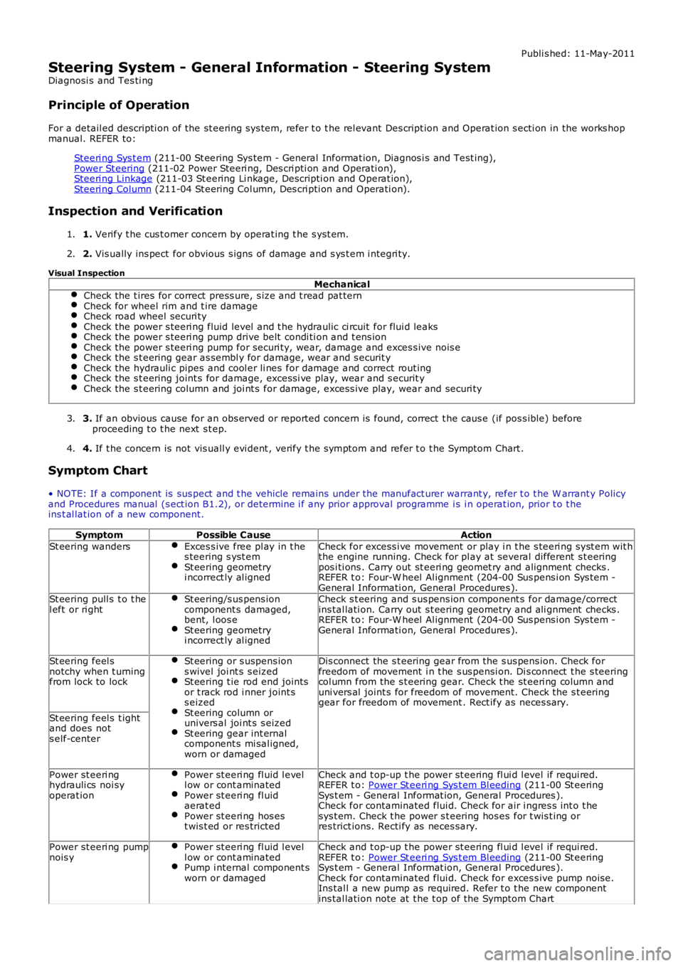
SymptomPossible CauseAction
St eering wandersExces s ive free pl ay in t hes teering s yst emSt eering geometryi ncorrect ly al igned
Check for excess i ve movement or play i n t he s teeri ng s yst em wit hthe engine running. Check for pl ay at several different s t eeringpos i ti ons . Carry out st eeri ng geomet ry and alignment checks .REFER t o: Four-W heel Al ignment (204-00 Sus pens i on Sys t em -General Informati on, General Procedures ).St eering pull s t o t hel eft or ri ghtSt eering/s us pens ioncomponent s damaged,bent, l oos eSt eering geometryi ncorrect ly al igned
Check s t eering and s us pens ion component s for damage/correctins tal lati on. Carry out s t eering geometry and ali gnment checks .REFER t o: Four-W heel Al ignment (204-00 Sus pens i on Sys t em -General Informati on, General Procedures ).
St eering feel snotchy when t urningfrom lock to lock
St eering or s uspens ions wivel joi nt s s eizedSt eering t ie rod end jointsor t rack rod i nner joint ss eizedSt eering column orunivers al joi nt s s eizedSt eering gear int ernalcomponent s mi sal igned,worn or damaged
Dis connect the s t eering gear from the s us pens ion. Check forfreedom of movement i n t he s us pensi on. Di s connect t he s teeringcol umn from the s t eering gear. Check t he st eeri ng col umn anduni vers al joint s for freedom of movement. Check the s t eeringgear for freedom of movement . Rect ify as neces s ary.
St eering feel s t ightand does nots elf-center
Power st eeri nghydrauli cs noi syoperat ion
Power st eeri ng fl uid l evell ow or cont aminatedPower st eeri ng fl uidaerat edPower st eeri ng hos est wis t ed or res tricted
Check and t op-up t he power st eering fl ui d l evel if requi red.REFER t o: Power St eeri ng Sys t em Bl eeding (211-00 St eeringSys t em - General Informat ion, General Procedures ).Check for contaminated flui d. Check for air i ngres s int o t hesys t em. Check t he power s t eering hos es for t wis t ing orres trict ions. Recti fy as neces sary.
Power st eeri ng pumpnois yPower st eeri ng fl uid l evell ow or cont aminatedPump i nternal component sworn or damaged
Check and t op-up t he power st eering fl ui d l evel if requi red.REFER t o: Power St eeri ng Sys t em Bl eeding (211-00 St eeringSys t em - General Informat ion, General Procedures ).Check for contaminated flui d. Check for exces s ive pump noi se.Ins tal l a new pump as required. Refer t o t he new componentins tal lati on note at t he t op of the Sympt om Chart