2006 LAND ROVER FRELANDER 2 bulb
[x] Cancel search: bulbPage 2486 of 3229
Publi s hed: 11-May-2011
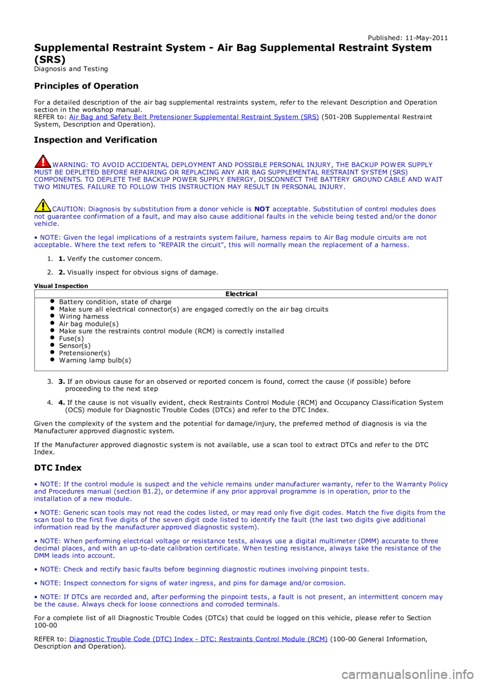
Supplemental Restraint System - Air Bag Supplemental Restraint System
(SRS)
Diagnosi s and Tes ti ng
Principles of Operation
For a detail ed descripti on of the ai r bag s upplement al res traints sys tem, refer t o the rel evant Des cript ion and Operat ions ect ion i n t he works hop manual .REFER to: Ai r Bag and Safety Bel t Pretens ioner Suppl ement al Res t raint Sys tem (SRS) (501-20B Suppl ement al Res t rai ntSyst em, Des cript ion and Operat ion).
Inspection and Verification
W ARNING: TO AVOID ACCIDENTAL DEPLOY MENT AND POSSIBLE PERSONAL INJURY , THE BACKUP POWER SUPPLYMUST BE DEPLETED BEFORE REPAIRING OR REPLACING ANY AIR BAG SUPPLEMENTAL RESTRAINT SYSTEM (SRS)COMPONENTS. TO DEPLETE THE BACKUP POW ER SUPPLY ENERGY , DISCONNECT THE BATTERY GRO UND CABLE AND W AITTW O MINUTES. FAILURE TO FOLLOW THIS INSTRUCTION MAY RESULT IN PERSONAL INJURY .
CAUTION: Di agnos is by s ubs ti tut ion from a donor vehicle is NO T acceptabl e. Subs ti tut ion of cont rol modules doesnot guarant ee confirmat ion of a faul t, and may als o caus e addit ional fault s i n t he vehi cl e being t est ed and/or t he donorvehi cl e.
• NOTE: Given t he l egal impl icati ons of a res t raint s s ys t em fail ure, harness repairs to Air Bag module ci rcuit s are notacceptable. W here t he t ext refers to "REPAIR the circui t", t hi s wi ll normal ly mean the repl acement of a harnes s .
1. Verify t he cus t omer concern.1.
2. Vis ually ins pect for obvious s igns of damage.2.
Visual Inspection
ElectricalBatt ery condit ion, s tat e of chargeMake s ure al l elect rical connect or(s) are engaged correct ly on the ai r bag ci rcuit sW iri ng harnes sAir bag modul e(s )Make s ure the rest rai nts control modul e (RCM) is correct ly ins tall edFuse(s )Sensor(s )Pret ensi oner(s )W arning l amp bulb(s)
3. If an obvious cause for an obs erved or report ed concern is found, correct t he caus e (if pos s ible) beforeproceeding t o t he next s t ep3.
4. If t he caus e is not vis ually evi dent , check Rest rai nts Cont rol Modul e (RCM) and Occupancy Cl ass i ficat ion Syst em(OCS) module for Diagnos t ic Troubl e Codes (DTCs ) and refer t o t he DTC Index.4.
Given t he complexit y of the s ys tem and the pot enti al for damage/injury, t he preferred met hod of di agnos is i s via theManufacturer approved diagnost ic sys tem.
If the Manufacturer approved di agnos ti c s ys t em i s not avai lable, use a s can tool to ext ract DTCs and refer to the DTCIndex.
DTC Index
• NOTE: If the control modul e is sus pect and t he vehicle remains under manufact urer warranty, refer to the W arrant y Poli cyand Procedures manual (s ect ion B1.2), or determine i f any prior approval programme is i n operat ion, prior t o t heins t al lat ion of a new modul e.
• NOTE: Generic scan t ool s may not read the codes li st ed, or may read only fi ve digit codes . Mat ch the five di git s from t hes can tool to the firs t fi ve di git s of the seven digi t code l is ted to ident ify t he faul t (t he las t t wo digi ts gi ve addi ti onalinformat ion read by the manufact urer approved diagnos t ic s ys tem).
• NOTE: W hen performing el ect ri cal volt age or resi s tance tes t s, al ways us e a digit al mult imet er (DMM) accurate to threedeci mal places , and wi th an up-to-date cali brat ion cert ificate. W hen t es ti ng res is t ance, always take t he res i st ance of t heDMM leads int o account.
• NOTE: Check and recti fy bas ic faul ts before beginni ng diagnos t ic rout ines i nvol vi ng pinpoint t es t s.
• NOTE: Ins pect connect ors for s igns of water ingres s , and pins for damage and/or corros ion.
• NOTE: If DTCs are recorded and, aft er performi ng the pi npoi nt tes ts , a fault is not present , an int ermi tt ent concern maybe t he caus e. Always check for loose connect ions and corroded terminals .
For a compl ete lis t of all Di agnos ti c Trouble Codes (DTCs) t hat could be logged on this vehicle, pleas e refer to Sect ion100-00
REFER to: Di agnos ti c Trouble Code (DTC) Index - DTC: Res trai nts Cont rol Module (RCM) (100-00 General Informati on,Des cript ion and Operat ion).
Page 2723 of 3229

Contents
3
R
Quick start
QUICK START ................................................... 7
Filling station information
FILLING STATION INFORMATION................... 33
Introduction
SYMBOLS GLOSSARY .................................... 35
LABEL LOCATIONS ......................................... 35
HEALTH AND SAFETY ..................................... 36
DATA RECORDING.......................................... 37
DISABILITY MODIFICATIONS ......................... 37
PARTS AND ACCESSORIES ............................ 37
Keys and remote controls
USING THE KEY .............................................. 40
GENERAL INFORMATION ON RADIO
FREQUENCIES ................................................ 40
USING THE REMOTE CONTROL ..................... 41
Locks
LOCKING AND UNLOCKING ............................ 44
Alarm
ARMING THE ALARM ..................................... 45
DISARMING THE ALARM ............................... 46
Seats
SITTING IN THE CORRECT POSITION ............ 47
MANUAL SEATS ............................................. 48
ELECTRIC SEATS ............................................ 49
HEAD RESTRAINTS ........................................ 51
REAR SEATS................................................... 51
HEATED SEATS............................................... 53
Seat belts
PRINCIPLE OF OPERATION ............................ 54
SEAT BELT REMINDER ................................... 55
FASTENING THE SEAT BELTS ........................ 56
SEAT BELT HEIGHT ADJUSTMENT................. 56
USING SEAT BELTS DURI NG PREGNANCY .... 57
Supplementary restraints system
PRINCIPLE OF OPERATION ............................ 58
AIRBAG WARNING LAMP ............................... 61
DISABLING THE PASSENGER AIRBAG ........... 62
AIRBAG SERVICE INFORMATION ................... 63
Child safety
CHILD SEATS ................................................. 64
BOOSTER CUSHIONS ..................................... 66
ISOFIX ANCHOR POINTS................................ 67
CHILD SAFETY LOCKS ................................... 69
Steering wheel
ADJUSTING THE STEERING WHEEL .............. 70
AUDIO CONTROL ........................................... 70
Lighting
LIGHTING CONTROL ...................................... 72
FRONT FOG LAMPS........................................ 72
REAR FOG LAMPS.......................................... 73
ADJUSTING THE HEADLAMPS....................... 73
HEADLAMP LEVELLING ................................. 73
HAZARD WARNING FLASHERS...................... 74
ADAPTIVE FRONT LIGHTING SYSTEM (AFS) . 74
DIRECTION INDICATORS ............................... 75
INTERIOR LAMPS .......................................... 76
APPROACH LAMPS ........................................ 76
CHANGING A BULB ........................................ 77
BULB SPECIFICATION CHART ........................ 86
Wipers and washers
WINDSCREEN WIPERS .................................. 87
RAIN SENSOR ................................................ 87
WINDSCREEN WASHERS............................... 88
HEADLAMP WASHERS................................... 88
REAR WINDOW WIPER AND WASHERS ........ 89
ADJUSTING THE WINDSCREEN WASHER JETS .
89
CHECKING THE WIPER BLADES .................... 90
CHANGING THE WIPER BLADES.................... 90
Windows and mirrors
ELECTRIC WINDOWS ..................................... 93
EXTERIOR MIRRORS ..................................... 94
ELECTRIC EXTERIOR MIRRORS .................... 95
INTERIOR MIRROR ........................................ 96
Instruments
INSTRUMENT PANEL OVERVIEW .................. 97
Information displays
TRIP COMPUTER ........................................... 99
INFORMATION MESSAGES ............................ 99
Page 2781 of 3229
61
Supplementary restraints system
R
Airbag deployment effectsAIRBAG WARNING LAMP
The airbag warning indicator is
mounted in the instrument pack,
and will illuminate as a bulb check
when the ignition is turned on.
If any of the following warning indicator
conditions occur, the vehicle should be
checked by your Land Ro ver Dealer/Authorised
repairer immediately.
• The warning indicator fails to illuminate
when the ignition is turned on.
• The warning indicator fails to extinguish
within six seconds of the ignition being
turned on.
• The warning indicator illuminates at any
time other than the bulb check, when the
ignition is turned on.WARNINGS
When an airbag inflates a fine powder
is released. This is normal, and not an
indication of a malf unction. However,
the powder may cause irritation to the skin,
and should be throughly flushed from eyes,
and any cuts or abrasions.
After inflation some airbag
components are at high temperatures.
To prevent injury, do no touch the
airbag components until they have cooled.
In order to react with sufficient speed,
airbags are deployed by an explosive
charge. Consequently airbag
deployment is accompan ied by a very loud
noise which may cause discomfort and
temporary loss of hearing.
WARNING
If the warning indicator signals that a
fault is present in the system, do not
use a child restraint on the front
passenger seat. Doing so will increase the risk
of death or serious injury to the child.
Page 2793 of 3229
73
Lighting
R
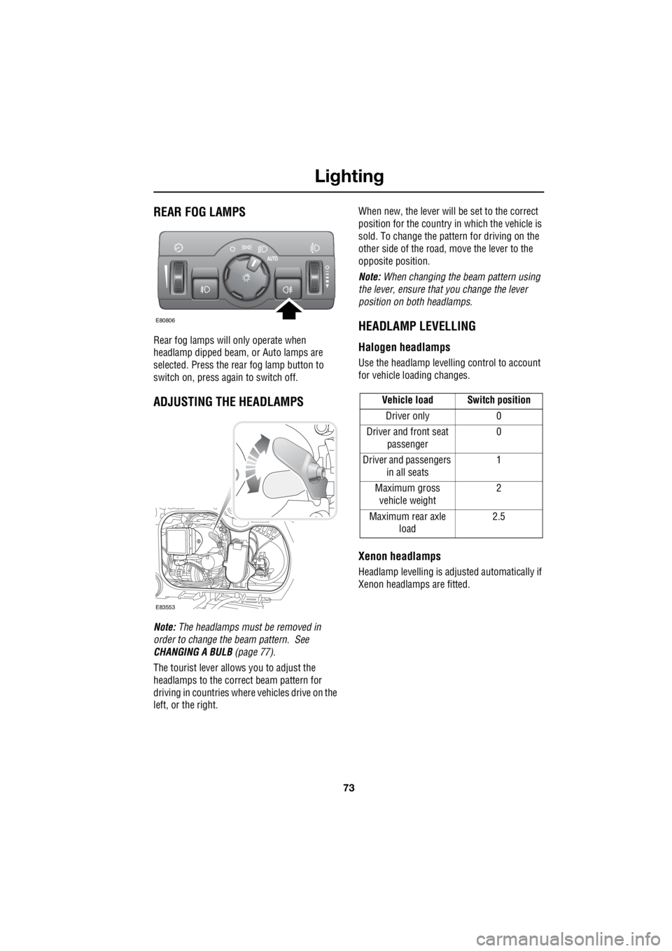
REAR FOG LAMPS
Rear fog lamps will only operate when
headlamp dipped beam, or Auto lamps are
selected. Press the rear fog lamp button to
switch on, press again to switch off.
ADJUSTING THE HEADLAMPS
Note: The headlamps must be removed in
order to change the beam pattern. See
CHANGING A BULB (page 77).
The tourist lever allows you to adjust the
headlamps to the correct beam pattern for
driving in countries where vehicles drive on the
left, or the right. When new, the lever will be set to the correct
position for the country in which the vehicle is
sold. To change the pattern for driving on the
other side of the road, move the lever to the
opposite position.
Note: When changing the beam pattern using
the lever, ensure that you change the lever
position on both headlamps.
HEADLAMP LEVELLING
Halogen headlamps
Use the headlamp levell ing control to account
for vehicle loading changes.
Xenon headlamps
Headlamp levelling is adju sted automatically if
Xenon headlamps are fitted.
E80806
E83553
Vehicle load Switch position
Driver only 0
Driver and front seat passenger 0
Driver and passengers in all seats 1
Maximum gross vehicle weight 2
Maximum rear axle load 2.5
Page 2797 of 3229
77
Lighting
R
CHANGING A BULB
General information
Note: In certain territori es it is a legal
requirement to carry spare bulbs. A
replacement bulb kit is available as an
approved accessory from your Land Rover
Dealer/Authorised Repairer.
Halogen bulbs
Halogen bulbs are used for main beam, dipped
beam, and front fog lamps. Take care not to
touch the glass part of the bulb with your
fingers; always use a cl oth to handle the bulb.
If necessary use methylated spirits to remove
finger prints. Xenon lamps
Seek advice a bout the correct
disposal of Bi-X enon lamp units
from a Land Rover
Dealer/Authorised Repairer, or your local
authority.
CAUTION
Alway replace bulbs with the correct
type and specification. If you are in any
doubt contact your Land Rover
Dealer/Authorised Repairer for advice.
WARNINGS
Replacement or maintenance of
Xenon lamps should only be carried
out by suitably qualified personnel.
High voltage is requi red to ignite the
gas and metal vapour which are used
to power Xenon lamps. Contact with
this voltage can cause serious injuries.
Bi-Xenon lamp units operate at a very
high temperature. Ensure that the
lamp units have cooled before
attempting to touch them.
Xenon lamp units contain Mercury
which is highly to xic, and can be
extremely harmful.
Page 2798 of 3229
Lighting
78
L
Removing the headlamp unit
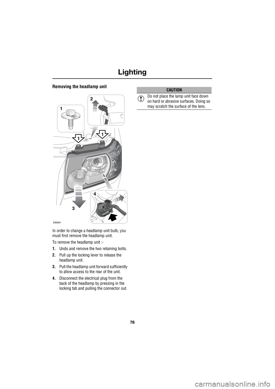
In order to change a headlamp unit bulb, you
must first remove the headlamp unit.
To remove the headlamp unit :-
1. Undo and remove the two retaining bolts.
2. Pull up the locking lever to release the
headlamp unit.
3. Pull the headlamp unit forward sufficiently
to allow access to the rear of the unit.
4. Disconnect the electrical plug from the
back of the headlamp by pressing in the
locking tab and pulling the connector out.
1
3
4
1
E80991
2
1
CAUTION
Do not place the la mp unit face down
on hard or abrasive surfaces. Doing so
may scratch the surface of the lens.
Page 2799 of 3229
79
Lighting
R
Headlamp unit bulbs
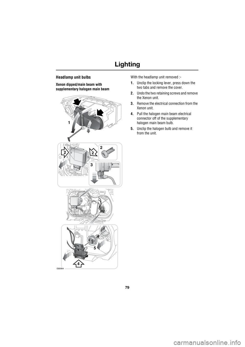
Xenon dipped/main beam with
supplementary halogen main beam With the headlamp unit removed :-
1. Unclip the locking lever, press down the
two tabs and remove the cover.
2. Undo the two retaining screws and remove
the Xenon unit.
3. Remove the electrical connection from the
Xenon unit.
4. Pull the halogen main beam electrical
connector off of the supplementary
halogen main beam bulb.
5. Unclip the halogen bulb and remove it
from the unit.
2
4
2
5
3
E80994
1
2
Page 2800 of 3229
Lighting
80
L
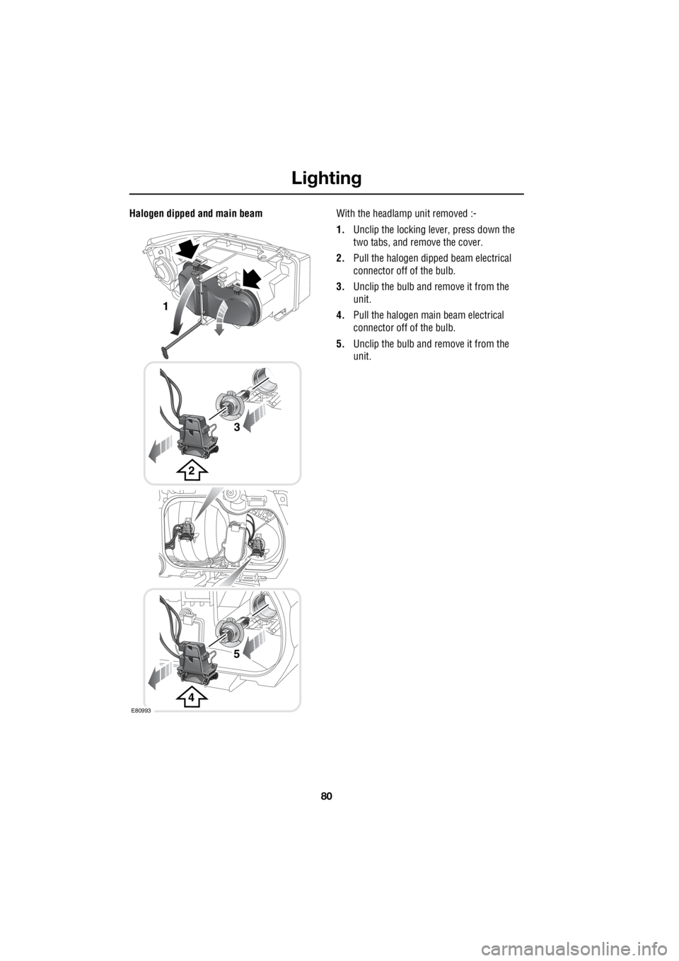
Halogen dipped and main beam With the headlamp unit removed :-
1. Unclip the locking lever, press down the
two tabs, and remove the cover.
2. Pull the halogen dipped beam electrical
connector off of the bulb.
3. Unclip the bulb and remove it from the
unit.
4. Pull the halogen main beam electrical
connector off of the bulb.
5. Unclip the bulb and remove it from the
unit.
2
3
1
4
5
E80993