2006 LAND ROVER FRELANDER 2 charging
[x] Cancel search: chargingPage 2564 of 3229
Publ is hed: 11-May-2011
Front End Sheet Metal Repairs - Fender Apron Panel Reinforcement
Removal and Installation
Removal
• NOTE: The fender apron panel reinforcement has to be unpicked from the fender apron panel service panel, it is not
available separately.
• NOTE: The RH panel is serviced less its weld studs 1. T he f e nd e r a p ro n p a ne l re i nf o rce me nt i s re p l a ce d i n
conjunct ion wit h:
Front bumper cover
Hood lat ch panel
Both front fenders
Fender apron upper panel
2. Fo r a d d i t i o na l i nf o rma t i o n re l a t i ng t o t hi s re p a i r p ro ce d ure
please see the following:
Fo r a d d i t i o na l i nf o rma t i o n, re f e r t o : Body and Frame
(501-26
Body Repairs - Vehicle Specific Information and Tolerance
Checks, Description and Operation) /
St a nd a rd W o rks ho p P ra ct i ce s
(100-00 Ge ne ra l I nf o rma t i o n,
Description and Operation).
3. Remove the fender apron upper panel.
Fo r a d d i t i o na l i nf o rma t i o n, re f e r t o : Fender Apron Upper Panel
(501-27 Front End Sheet Met al Re pai rs , Removal and
Installation).
4. Remove the front shock absorber.
Fo r a d d i t i o na l i nf o rma t i o n, re f e r t o : Front Shock Abs orber
(204-01 Front Suspension, Removal and Installation).
5. LH Side: Remove the engine support insulator.
Fo r a d d i t i o na l i nf o rma t i o n, re f e r t o : Engine Upper Support
Insulator (303-01B Engi ne - TD4 2.2L Di es el, Removal and
Installation).
6. LH Side: Remove the bat tery t ray.
Fo r a d d i t i o na l i nf o rma t i o n, re f e r t o : Battery Tray
(414-01
Battery, Mounting and Cables, Removal and Installation).
7. LH Side: Remove the air intake pipe.
8. LH Side: Release the battery junction box and position aside.
9. RH Side: Remove the windshield washer reservoir.
Fo r a d d i t i o na l i nf o rma t i o n, re f e r t o : Windshield Washer
Res ervoi r (501-16 W i pers and W as hers , Removal and
Installation).
10. RH Side: Remove the engine mounting bracket.
Fo r a d d i t i o na l i nf o rma t i o n, re f e r t o : Engine Mount RH
(303-01B
Engine - TD4 2.2L Diesel, Removal and Installation).
11. RH Side: Release the coolant expansion tank and lay it
aside.
12. RH Side: Evacuate the A/C system.
Fo r a d d i t i o na l i nf o rma t i o n, re f e r t o : Air Conditioning (A/C)
System Recovery, Evacuation and Charging (412-00 Cl i mat e
Co nt ro l Sys t e m - Ge ne ra l I nf o rma t i o n, Ge ne ra l P ro ce d ure s ).
13. RH Side: Remove the fender apron A/C pipes.
14. RH Side: Release and lay aside the insulating material at the
bulkhead.
15. Release and lay aside the wiring harness.
Page 2705 of 3229
Publ is hed: 11-May-2011
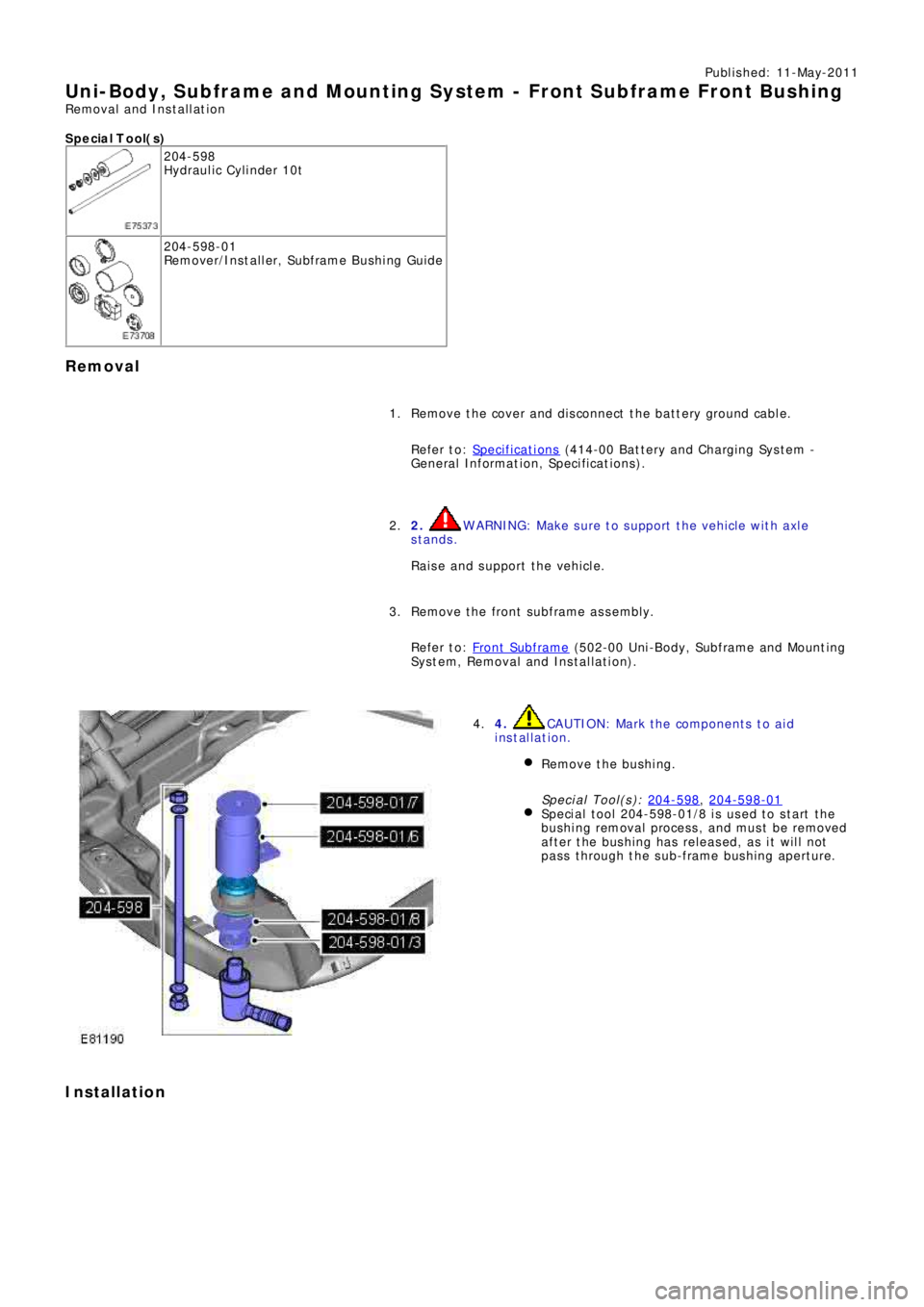
Uni-Body, Subframe and Mounting System - Front Subframe Front Bushing
Removal and Installation
S p e c ia l T o o l( s )
204-598
Hydraulic Cylinder 10t
204-598-01
Re mo ve r/I ns t a l l e r, Sub f ra me B us hi ng Gui d e
Removal
Remove the cover and disconnect the battery ground cable.
Refer to: Specifications
(414-00 Battery and Charging System -
General Information, Specifications). 1.
2.
WARNING: Make sure to support the vehicle with axle
stands.
Raise and support the vehicle. 2.
Re mo ve t he f ront s ubf ra me a s s e mbl y.
Refer to: Front Subframe
(502-00 Uni-Body, Subframe and Mounting
System, Removal and Installation). 3.
4. CAUTION: Mark the components to aid
installation.
Remove the bushing.
Special Tool(s): 204-598
, 204-598-01Speci al t ool 204-598-01/8 i s us ed t o s t art t he
bushing removal process, and must be removed
after the bushing has released, as it will not
pass through the sub-frame bushing aperture.
4.
Installation
Page 2706 of 3229
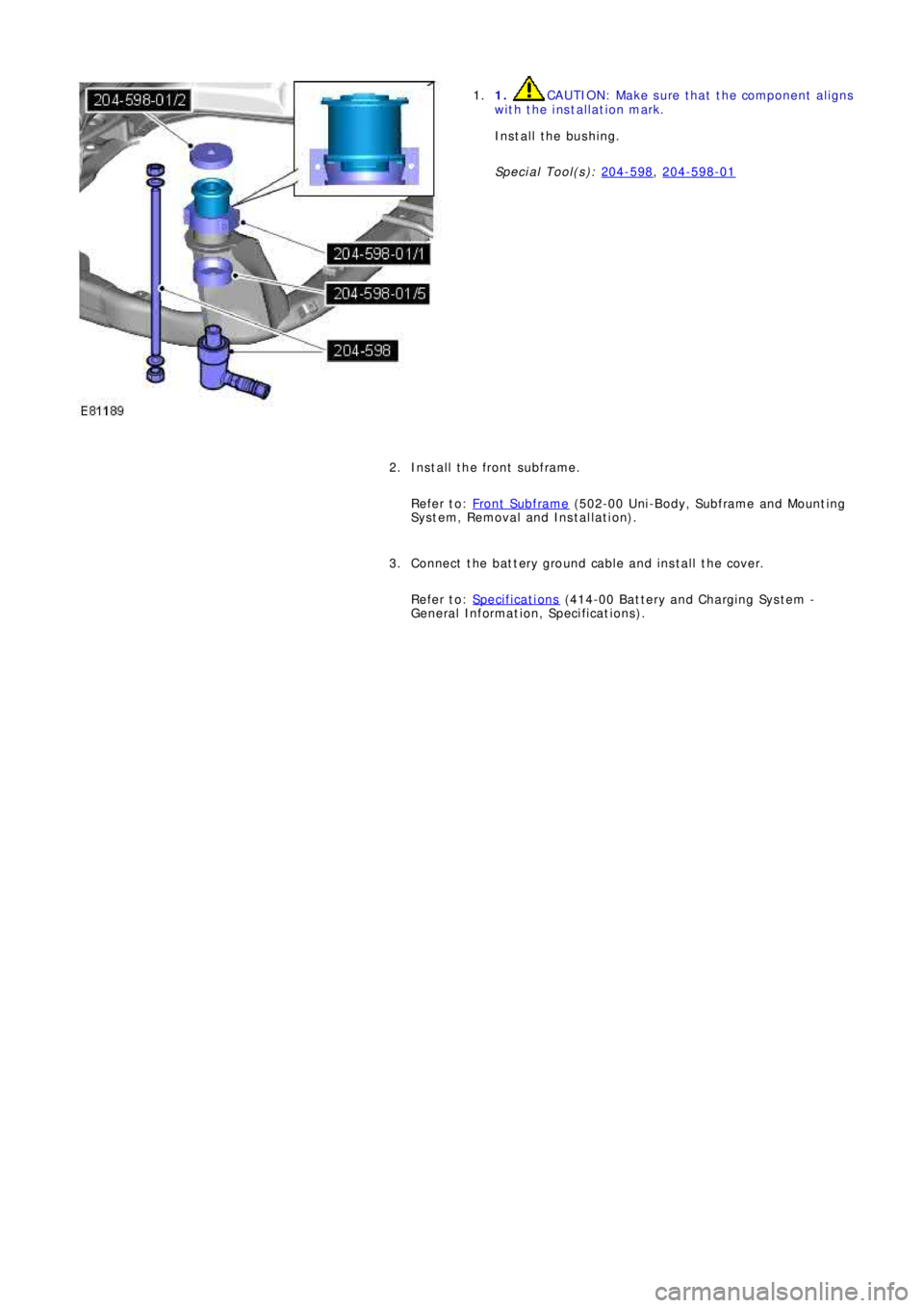
1. CAUTION: Make sure that the component aligns
with the installation mark.
Install the bushing.
Special Tool(s): 204-598
, 204-598-01
1.
Install the front subframe.
Refer to: Front Subframe
(502-00 Uni-Body, Subframe and Mounting
System, Removal and Installation). 2.
Connect the battery ground cable and install the cover.
Refer to: Specifications
(414-00 Battery and Charging System -
General Information, Specifications). 3.
Page 2707 of 3229
Publ is hed: 11-May-2011
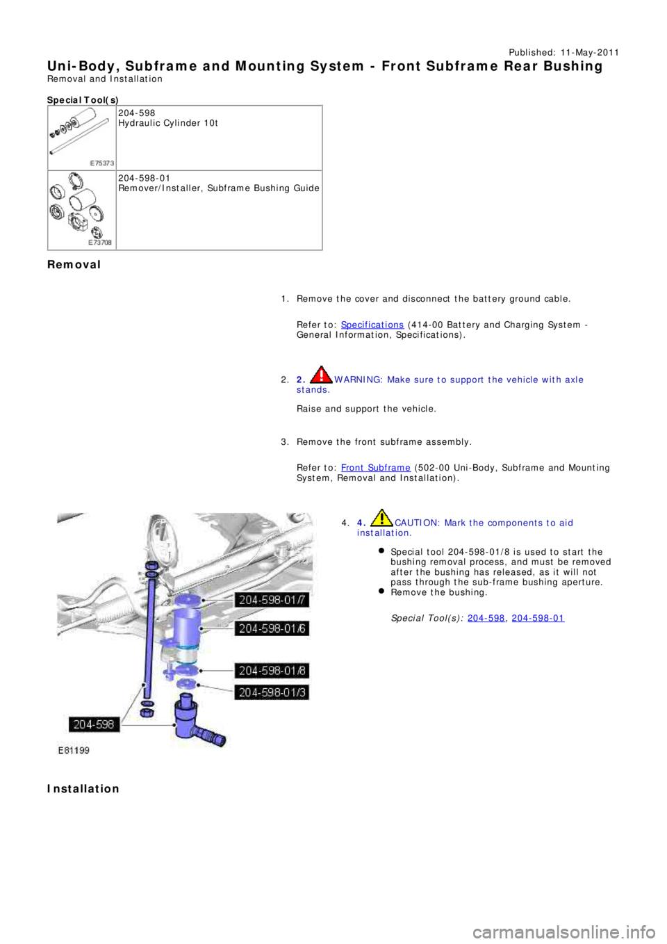
Uni-Body, Subframe and Mounting Syst em - Front Subframe Rear Bushing
Removal and Installation
S p e c ia l T o o l( s )
204-598
Hydraulic Cylinder 10t
204-598-01
Re mo ve r/I ns t a l l e r, Sub f ra me B us hi ng Gui d e
Removal
Remove the cover and disconnect the battery ground cable.
Refer to: Specifications
(414-00 Battery and Charging System -
General Information, Specifications).
1.
2.
WARNING: Make sure to support the vehicle with axle
stands.
Raise and support the vehicle.
2.
Re mo ve t he f ront s ubf ra me a s s e mbl y.
Refer to: Front Subframe
(502-00 Uni-Body, Subframe and Mounting
System, Removal and Installation).
3.
4. CAUTION: Mark the components to aid
installation.
Speci al t ool 204-598-01/8 i s us ed t o s t art t he
bushing removal process, and must be removed
after the bushing has released, as it will not
pass through the sub-frame bushing aperture.
Remove the bushing.
Special Tool(s): 204-598
, 204-598-01
4.
Installation
Page 2708 of 3229
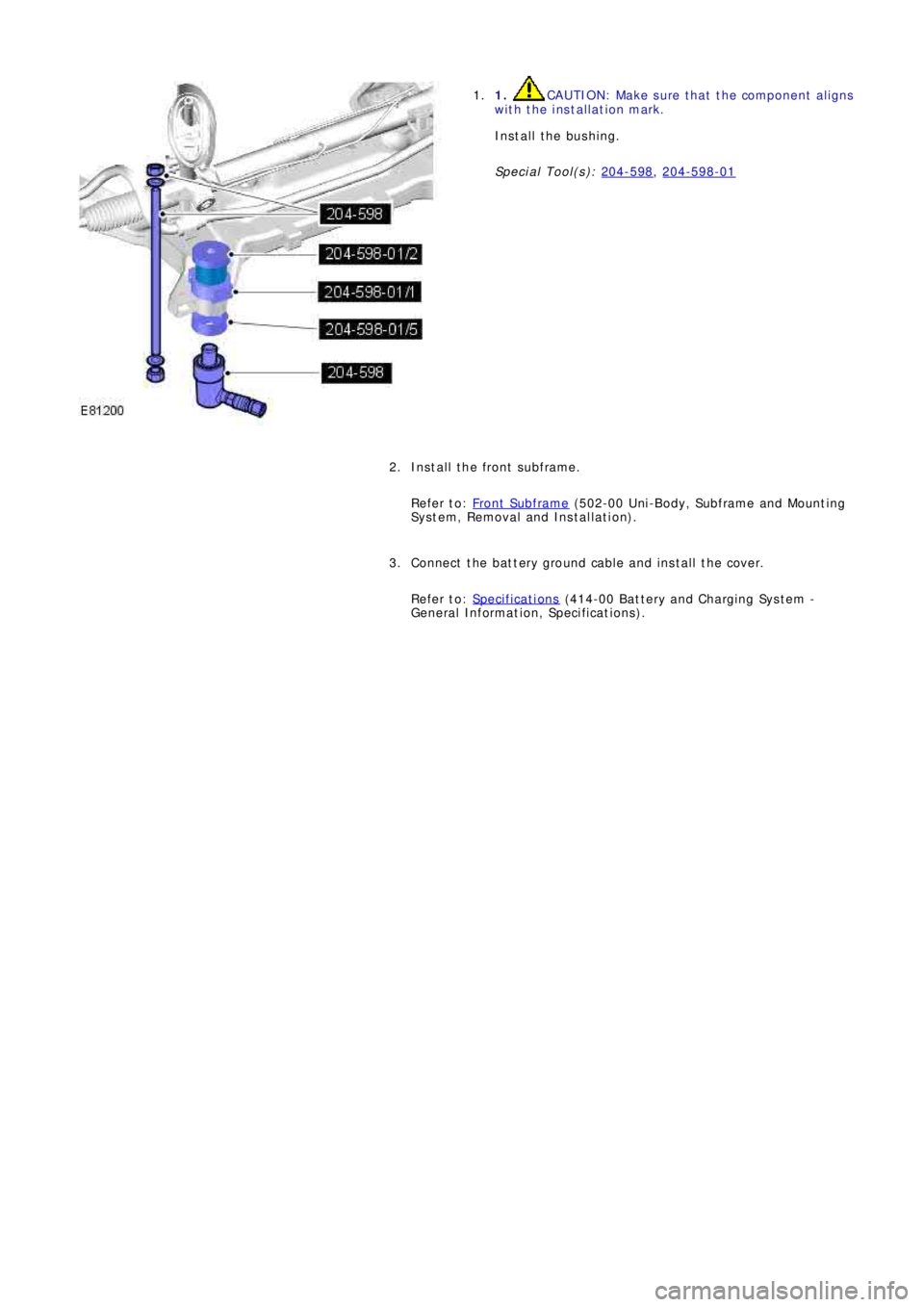
1. CAUTION: Make sure that the component aligns
with the installation mark.
Install the bushing.
Special Tool(s): 204-598
, 204-598-01
1.
Install the front subframe.
Refer to: Front Subframe
(502-00 Uni-Body, Subframe and Mounting
System, Removal and Installation).
2.
Connect the battery ground cable and install the cover.
Refer to: Specifications
(414-00 Battery and Charging System -
General Information, Specifications).
3.
Page 2725 of 3229

Contents
5
R
ENGINE COOLANT CHECK ............................ 163
BRAKE AND CLUTCH FLUID CHECK ............. 165
POWER STEERING FLUID CHECK ................ 166
WASHER FLUID CHECK ................................ 167
TECHNICAL SPECIFICATIONS ...................... 169
Vehicle battery
BATTERY WARNING SYMBOLS ................... 171
BATTERY CARE ............................................ 171
USING BOOSTER CABLES ............................ 173
CHARGING THE VE HICLE BATTERY ............. 174
CHANGING THE VE HICLE BATTERY ............. 174
Wheels and tyres
GENERAL INFORMATION ............................. 176
TYRE CARE ................................................... 177
USING WINTER TYRES................................. 183
CHANGING A ROAD WHEEL ......................... 183
TYRE REPAIR KIT ......................................... 187
USING SNOW CHAINS.................................. 192
TYRE GLOSSARY.......................................... 193
TECHNICAL SPECIFICATIONS ...................... 194
Fuses
FUSE BOX LOCATIONS ................................. 195
CHANGING A FUSE ....................................... 195
FUSE SPECIFICATION CHART....................... 196
Emergency equipment
HAZARD WARNING FLASHERS .................... 204
WARNING TRIANGLE ................................... 204
Status after a collision
DRIVING AFTER A COLLISION...................... 205
INSPECTING SAFETY SYSTEM COMPONENTS ...
206
Vehicle recovery
TOWING POINTS .......................................... 207
LASHING POINTS ......................................... 208
TRANSPORTING THE VEHICLE..................... 208
TOWING THE VEHICLE ON FOUR WHEELS .. 208
Vehicle identification
VEHICLE IDENTIFICATION PLATE................. 210
VEHICLE IDENTIFI CATION NUMBER (VIN) ... 210
VEHICLE BUILD DATE PLATE ....................... 210
Technical specifications
ENGINE SPECIFICATIONS ............................ 211
WEIGHTS...................................................... 212
DIMENSIONS................................................ 213
Type approval
Declarations of conformity ........................... 215
Audio introduction
RADIO RECEPTION....................................... 218
Audio unit overview
AUDIO UNIT OVERVIEW............................... 219
Audio unit operation
ON OR OFF CONTROL .................................. 223
VOLUME CONTROL ...................................... 223
AUDIO CONTROL ......................................... 223
WAVEBAND BUTTON ................................... 224
AUTOSTORE CONTROL ................................ 225
STATION PRESET BUTTONS ........................ 226
TRAFFIC INFORMATION CONTROL .............. 226
Audio unit menus
RADIO DATA SYSTEM (RDS) ....................... 228
REGIONAL MODE (REG) .............................. 228
ENHANCED OTHER NETWORK (RDS-EON).. 229
ALTERNATIVE FREQUENCIES ...................... 229
NEWS BROADCASTS ................................... 230
PRIORITY PROGRAMME TYPE (PTY) .......... 231
RESETTING THE AUDIO UNIT ...................... 233
Digital audio broadcasting
GENERAL INFORMATION ............................. 234
AUDIO CONTROLS ....................................... 235
DISPLAY OPTIONS ....................................... 236
CHANNEL AUTOMATIC TUNING................... 236
CHANNEL OPTIONS ..................................... 236
PRESET BUTTONS ....................................... 238
SETTINGS..................................................... 240
Compact disc player
LOADING COMPACT DISCS ......................... 245
EJECTING COMPACT DISCS ........................ 246
EJECTING MULTIPLE CO MPACT DISCS....... 246
COMPACT DISC SELECTION ........................ 246
COMPACT DISC PLAYBACK ......................... 246
Page 2848 of 3229
Driving hints
128
L
Driving hintsGENERAL DRIVING POINTS
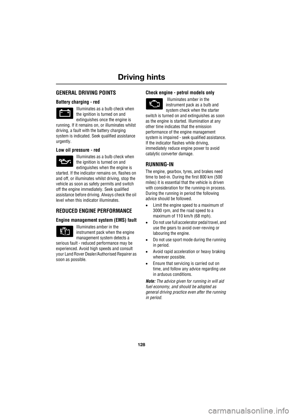
Battery charging - red
Illuminates as a bulb check when
the ignition is turned on and
extinguishes once the engine is
running. If it remains on, or illuminates whilst
driving, a fault with the battery charging
system is indicated. Seek qualified assistance
urgently.
Low oil pressure - red
Illuminates as a bulb check when
the ignition is turned on and
extinguishes when the engine is
started. If the indicator remains on, flashes on
and off, or illuminates whilst driving, stop the
vehicle as soon as safety permits and switch
off the engine immediat ely. Seek qualified
assistance before driving. Always check the oil
level when this indicator illuminates.
REDUCED ENGINE PERFORMANCE
Engine management syst em (EMS) fault
Illuminates amber in the
instrument pack when the engine
management system detects a
serious fault - reduce d performance may be
experienced. Avoid high speeds and consult
your Land Rover Dealer/A uthorised Repairer as
soon as possible.
Check engine - petrol models only
Illuminates amber in the
instrument pack as a bulb and
system check when the starter
switch is turned on and extinguishes as soon
as the engine is starte d. Illumination at any
other time indicates that the emission
performance of the engine management
system is impaired - seek qualified assistance.
If the indicator flashes while driving,
immediately reduce e ngine power to avoid
catalytic converter damage.
RUNNING-IN
The engine, gearbox, tyre s, and brakes need
time to bed-in. During the first 800 km (500
miles) it is essential th at the vehicle is driven
with consideration for the running-in process.
During the running in period the following
advice should be followed.
• Limit the engine speed to a maximum of
3000 rpm, and the road speed to a
maximum of 110 km/h (68 mph).
• Do not use full accelerator pedal travel, and
use the gears to avoid over-revving or
labouring the engine.
• Do not use sport mode during the running
in period.
• Avoid rapid accelerati on or heavy braking
wherever possible.
• Ensure that servicing is carried out on
time, and follow any advice regarding use
in arduous conditions.
Note: The advice given for running in will aid
fuel economy, and s hould be adopted as
general driving practice even after the running
in period.
Page 2894 of 3229
Vehicle battery
174
L
CHARGING THE VEHICLE BATTERY
1. Disconnect the battery and remove it from
the vehicle.
2. Connect the battery charger in accordance
with the charger manufacturer's
instructions.
3. Once the charge is complete switch off the
power to the charger.
4. Disconnect the charger cables from the
battery.
5. Allow the battery to stand for an hour
before connecting to the vehicle. This will
allow any explosive gasses to dissipate,
and reduce the risk of explosion.
CHANGING THE VEHICLE BATTERY
Disconnecting
1. Ensure that all electrical circuits are
switched off, all windows are closed, and
the alarm is disarmed.
2. Remove the remote control from the
vehicle and wait two minutes to allow the
systems to power down fully.
3. Undo the negative clam p, and lift the cable
and clamp clear of th e battery terminal.
4. Undo the positive clamp, and lift the cable
and clamp clear of th e battery terminal.
5. Undo the battery clamp and lift the battery
clear of the vehicle.
WARNINGS
Ensure that the charger used is of the
correct type and rating for the battery.
Using an unsuitable charger may damage the
battery, and could cause the battery to
explode.
Always charge the battery in a well
ventilated area away from any naked
flames, sparks or ot her ignition sources.
During charging the battery can produce a
highly explosive a nd flammable gas.
CAUTIONS
The battery must be disconnected and
removed from the vehicle before
charging. Failure to do so could result in
damage to the vehicle's electrical system.
Always follow the instructions supplied
with the battery charger. Failure to do so
may result in damage to the battery.
WARNINGS
Use caution when lifting the battery out
of, or into, the vehicl e. It is heavy, and
may cause injury when lifting, or if dropped.
Do not tip the battery when lifting or
moving as tilting the battery more than
45 degrees may damage the battery, and may
cause the electrolyte to leak out. Battery
electrolyte is highly corrosive, and toxic.
CAUTIONS
Do not rest the battery on any part of the
vehicle as it may ca use damage due to
it's weight.
Do not run the engine with the battery
disconnected. Doing so may damage the
charging system.