2006 LAND ROVER FRELANDER 2 brake pads
[x] Cancel search: brake padsPage 423 of 3229
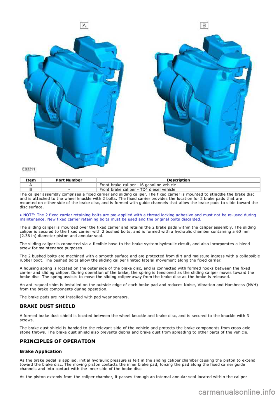
ItemPart NumberDescription
A-Front brake cal iper - i6 gas oli ne vehi cl eB-Front brake cal iper - TD4 dies el vehicle
The cal iper as sembl y compris es a fixed carrier and s li ding caliper. The fi xed carrier i s mounted t o s t raddle t he brake di scand is at t ached t o t he wheel knuckl e wit h 2 bol ts . The fixed carri er provides the locat ion for 2 brake pads t hat aremounted on ei ther s ide of t he brake di sc, and is formed wit h guide channel s t hat al low t he brake pads t o s li de toward t hedis c s urface.
• NOTE: The 2 fixed carrier ret aining bol ts are pre-appl ied wi th a t hread locking adhesi ve and mus t not be re-us ed duringmaint enance. New fixed carri er ret ai ning bolt s mus t be us ed and t he ori gi nal bolt s di scarded.
The s li di ng cal iper is mount ed over the fixed carrier and ret ains t he 2 brake pads wi thi n the cal iper as s embly. The s li di ngcal iper is secured t o t he fixed carri er wit h 2 bus hed bol ts , and i s formed wi th a hydraul ic chamber cont ai ning a 60 mm(2.36 in) di ameter pis t on and annular s eal.
The s li di ng cal iper is connect ed via a fl exi ble hos e t o t he brake s yst em hydrauli c circui t, and als o i ncorporates a bleeds crew for maint enance purposes .
The 2 bus hed bol ts are machined wi th a s mooth surface and are protect ed from di rt and moi st ure ingres s wi th a col laps iblerubber boot . The bushed bolt s all ow t he s li di ng caliper li mi ted l ateral movement along t he fi xed carri er.
A hous ing s pri ng is locat ed on t he outer s ide of t he brake dis c, and is connect ed wit h formed hooks between t he fixedcarri er and sl idi ng cal iper. During operat ion of t he brake, t he s pri ng is tens ioned as the sl iding cal iper moves toward thebrake dis c. The s pring as s is t s to move t he sl idi ng cal iper away from t he brake di sc as the brake is released.
An anti -s queal s him i s ins tal led on t he outs i de edge of each brake pad and reduces Nois e, Vibrat ion and Hars hnes s (NVH)from the brake component s duri ng operati on.
The brake pads are not i nst all ed wit h pad wear s ens ors .
BRAKE DUST SHIELD
A formed brake dust s hiel d is locat ed between t he wheel knuckle and brake di s c, and i s s ecured to the knuckl e wit h 3s crews .
The brake dus t shi eld i s handed t o t he rel evant s ide of t he vehicle and protects t he brake component s from cros s axl es tone t hrows . The brake dus t shi el d als o prevent s debris and brake dust from s preading t o other part s of t he vehi cl e.
PRINCIPLES OF OPERATION
Brake Application
As t he brake pedal i s applied, ini ti al hydrauli c pres s ure i s fel t in the s l iding cali per chamber caus ing t he pis t on to ext endt oward t he brake dis c. The moving pis t on cont act s t he inner brake pad, forci ng the pad al ong the fixed carrier guidechannels and i nto cont act wi th the i nner s ide of t he brake di sc.
As t he pis ton ext ends from t he cal iper chamber, it pas ses t hrough an i nternal annul ar seal located wit hi n t he cal iper
Page 424 of 3229
chamber. The movement of t he pis t on dis torts t he s hape of the s eal and cons equent ly, the s eal appl ies pres s ure on thepis t on out er s urface.
The s li di ng cal iper now react s and commences t o s li de along t he 2 bus hed bol ts , i n the oppos it e direct ion t o t he extendingpis t on. The s li ding cali per contacts t he outer brake pad, forcing t he pad along t he fi xed carri er gui de channels and i nt ocont act wit h the out er si de of the brake dis c. The hous ing s pri ng t hat i s att ached bet ween the fi xed carrier and s li dingcal iper is tens ioned as t he sl idi ng cal iper moves toward the brake dis c.
W i th bot h brake pads now in full cont act wit h the brake dis c and hydraulic pres sure act ing on the pi s ton, no furthermovement of t he pis t on and s li di ng cal iper is pos s ible. The force creat ed by the pi ston and cali per acti ng agai nst the brakepads increas es rapidly, t rapping t he brake di sc and sl owing t he vehi cl e.
Brake Release
As t he brake pedal i s rel eas ed, hydraul ic press ure in the cali per chamber coll apses and force i s no longer appl ied t o t hebrake pads. The brake pads are moved s li ght ly out wards by t he acti on of the rotat ing brake di s c, and t he caliper int ernalannul ar seal ret urns t o t he normal s hape. As t he s eal moves i t gri ps on the pi s ton out er s urface and wit hdraws t he pis t onint o t he chamber, suffi ci ent ly to provi de t he neces sary pad t o dis c clearance.
This acti on prevents t he pis t on from hol di ng t he inner brake pad agai nst t he dis c, and als o enables t he pis ton to protrudefurther from the cali per chamber to compens at e for brake pad wear.
W i th no pres s ure being appli ed t o the hydraul ic s yst em, t he hous i ng spring t ensi on is al s o rel ieved and the spring returnst o the normal pos i ti on. As t he housi ng s pri ng moves , t he att ached s l iding cali per i s moved away from the out er s i de of thedis c t o provide the neces s ary cl earance bet ween the out er brake pad and the brake dis c.
Page 426 of 3229
Publi s hed: 11-May-2011
Front Disc Brake - Brake Pads
Removal and Inst all ati on
Removal
1. W ARNING: Do not work on or under a vehi cle s upported onl yby a jack. Al ways support t he vehi cl e on s afet y s tands .
Rais e and s upport t he vehi cl e.
1.
Remove t he front wheel s and ti res .
Refer t o: W heel and Ti re (204-04 W heel s and Tires, Removal andInst all at ion).
2.
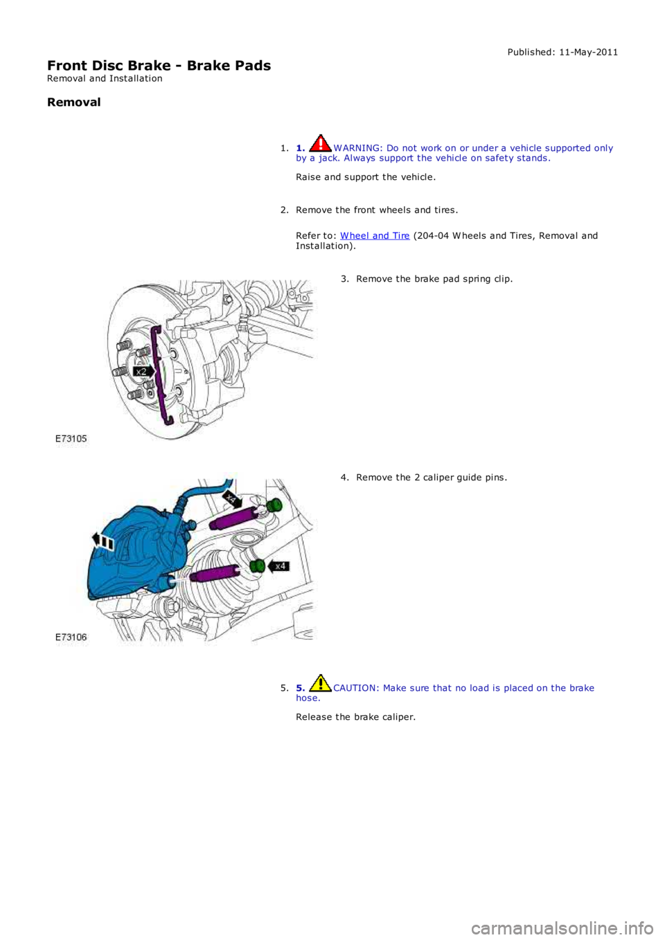
Remove t he brake pad s pri ng cl ip.3.
Remove t he 2 caliper guide pi ns .4.
5. CAUTION: Make s ure that no load i s placed on t he brakehos e.
Releas e t he brake caliper.
5.
Page 427 of 3229
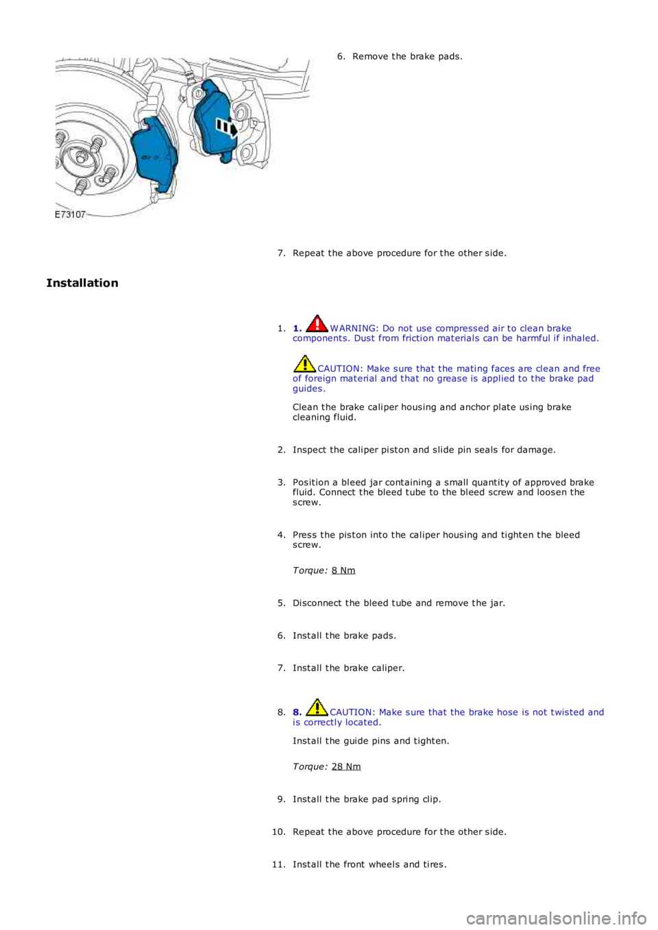
Remove t he brake pads.
6.
Repeat t he above procedure for t he other s ide.
7.
Installation
1. W ARNING: Do not use compress ed air t o clean brake
component s. Dus t from fricti on mat erial s can be harmful i f inhaled. CAUTION: Make s ure that t he mati ng faces are cl ean and free
of foreign mat eri al and t hat no greas e is appl ied t o t he brake pad
guides .
Clean t he brake cali per hous ing and anchor pl at e us ing brake
cleaning fluid.
1.
Inspect the cali per pi st on and s li de pin seals for damage.
2.
Pos it ion a bl eed jar cont aining a s mall quant it y of approved brake
fluid. Connect t he bleed t ube to the bl eed screw and loos en t he
s crew.
3.
Pres s t he pis t on int o t he cal iper hous ing and ti ght en t he bleed
s crew.
T orque: 8 Nm 4.
Di sconnect t he bleed t ube and remove t he jar.
5.
Inst all t he brake pads.
6.
Inst all t he brake caliper.
7.
8. CAUTION: Make s ure that the brake hose is not t wis ted and
i s correctl y located.
Inst all t he gui de pins and t ight en.
T orque: 28 Nm 8.
Inst all t he brake pad s pri ng cl ip.
9.
Repeat t he above procedure for t he other s ide.
10.
Inst all t he front wheel s and ti res .
11.
Page 436 of 3229
The brake dis c al so forms t he locati on for t he parking brake component s . The brake d is c i nt ernal diamet er is 185 mm (7.28
in) and i s machined wit h a smoot h s urface to form t he brake drum. An int egral backpl
ate and brake dust s hiel d is mount ed
t o the rear of the brake di s c. The backpl at e enclos es the brake dis c and als o provi d es the mount ing l ocat ion for t he 2
parking brake shoes and operat ing component s.
An apert ure i s formed i n t he dust s hiel d and backplat e t hat al lows t he parking brake cable to protrude t hrough to the i nner
s ide of t he brake dis c, and connect to t he parki ng brake expander uni t. A hol e machi ned i n t he brake dis c outer hub
provides acces s t o t he parking brake manual adjus ter.
For addit ional informat ion, refer t o: Parking Brake (206-05 Parki ng Brake and Act uat ion, Descripti on and Operat ion).
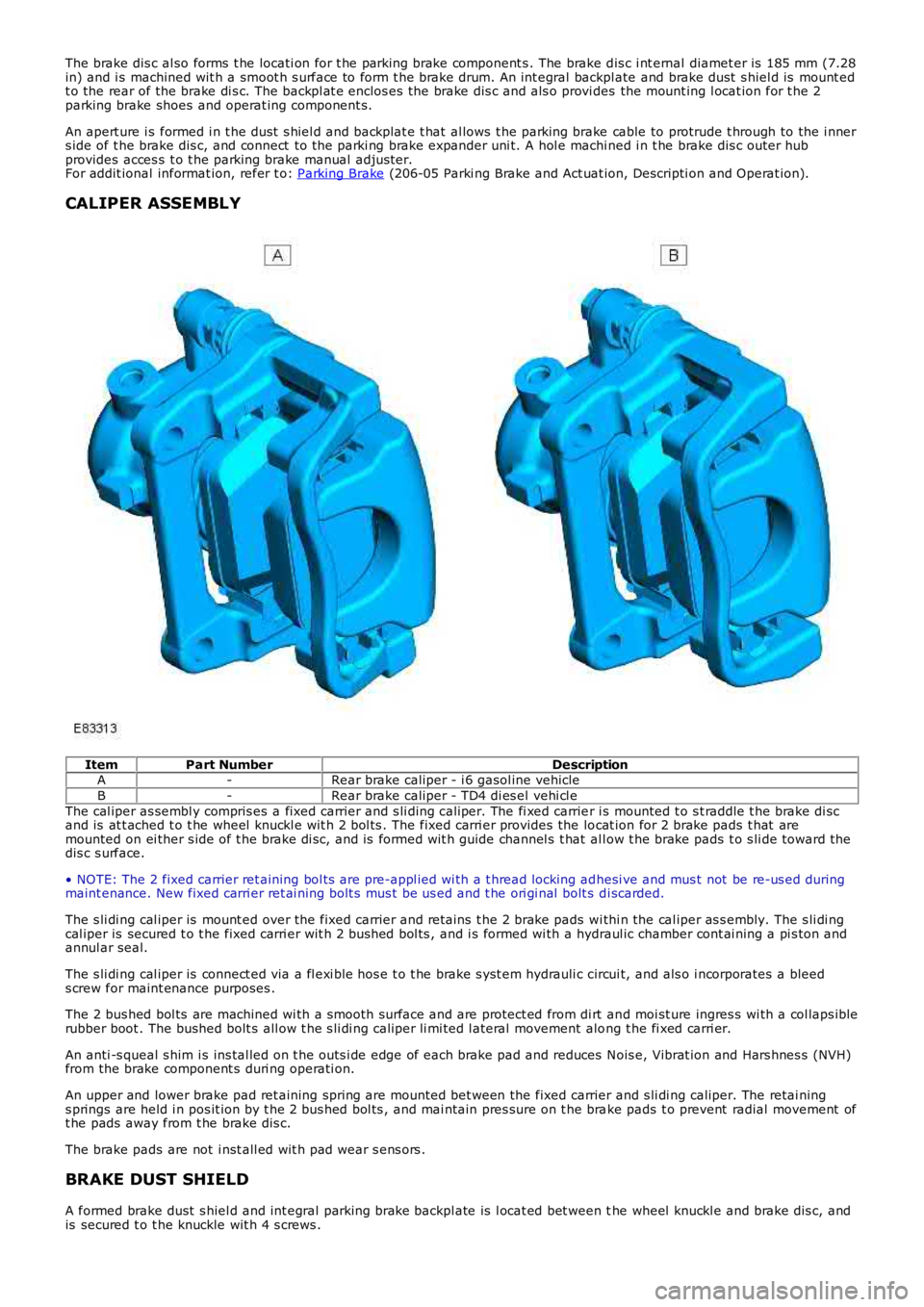
CALIPER ASSEMBLY Item
Part Number Description
A -Rear brake caliper - i 6 gasol ine vehicle
B -Rear brake caliper - TD4 di es el vehi cl e
The cal iper as sembl y compris es a fixed carrier and s li ding caliper. The fi xed carrie r i s mounted t o s t raddle t he brake di sc
and is at t ached t o t he wheel knuckl e wit h 2 bol ts . The fixed carri er provides the lo cat ion for 2 brake pads t hat are
mounted on ei ther s ide of t he brake di sc, and is formed wit h guide channel s t hat al l ow t he brake pads t o s li de toward t he
dis c s urface.
• NOTE: The 2 fixed carrier ret aining bol ts are pre-appl ied wi th a t hread locking ad hesi ve and mus t not be re-us ed during
maint enance. New fixed carri er ret ai ning bolt s mus t be us ed and t he ori gi nal bolt s d i scarded.
The s li di ng cal iper is mount ed over the fixed carrier and ret ains t he 2 brake pads w i thi n the cal iper as s embly. The s li di ng
cal iper is secured t o t he fixed carri er wit h 2 bus hed bol ts , and i s formed wi th a hy draul ic chamber cont ai ning a pi s ton and
annul ar seal.
The s li di ng cal iper is connect ed via a fl exi ble hos e t o t he brake s yst em hydrauli c c ircui t, and als o i ncorporates a bleed
s crew for maint enance purposes .
The 2 bus hed bol ts are machined wi th a s mooth surface and are protect ed from di rt an d moi st ure ingres s wi th a col laps ible
rubber boot . The bushed bolt s all ow t he s li di ng caliper li mi ted l ateral movement alo ng t he fi xed carri er.
An anti -s queal s him i s ins tal led on t he outs i de edge of each brake pad and reduces N ois e, Vibrat ion and Hars hnes s (NVH)
from the brake component s duri ng operati on.
An upper and lower brake pad ret aining spring are mounted bet ween the fixed carrier and s li di ng caliper. The retai ning
s prings are held i n pos it ion by t he 2 bus hed bol ts , and mai ntain pres sure on t he bra ke pads t o prevent radial movement of
t he pads away from t he brake dis c.
The brake pads are not i nst all ed wit h pad wear s ens ors .
BRAKE DUST SHIELD
A formed brake dust s hiel d and int egral parking brake backpl ate is l ocat ed bet ween t he wheel knuckl e and brake dis c, and
is secured t o t he knuckle wit h 4 s crews .
Page 437 of 3229
The brake dus t shi eld i s handed t o t he rel evant s ide of t he vehicle and protects t he brake component s from cros s axl e
s tone t hrows . The brake dus t shi el d als o prevent s debris and brake dust from s preadi
ng t o other part s of t he vehi cl e.
PRINCIPLES OF OPERATION
Brake Application
As t he brake pedal i s applied, ini ti al hydrauli c pres s ure i s fel t in the s l iding cal i per chamber caus ing t he pis t on to ext end
t oward t he brake dis c. The moving pis t on cont act s t he inner brake pad, forci ng the p ad al ong the fixed carrier guide
channels and i nto cont act wi th the i nner s ide of t he brake di sc.
As t he pis ton ext ends from t he cal iper chamber, it pas ses t hrough an i nternal annul a r seal located wit hi n t he cal iper
chamber. The movement of t he pis t on dis torts t he s hape of the s eal and cons equent ly, the s eal appl ies pres s ure on the
pis t on out er s urface.
The s li di ng cal iper now react s and commences t o s li de along t he 2 bus hed bol ts , i n t he oppos it e direct ion t o t he extending
pis t on. The s li ding cali per contacts t he outer brake pad, forcing t he pad along t he fi xed carri er gui de channels and i nt o
cont act wit h the out er si de of the brake dis c.
W i th bot h brake pads now in full cont act wit h the brake dis c and hydraulic pres sure act ing on the pi s ton, no further
movement of t he pis t on and s li di ng cal iper is pos s ible. The force creat ed by the pi s ton and cali per acti ng agai nst the brake
pads increas es rapidly, t rapping t he brake di sc and sl owing t he vehi cl e.
Brake Release
As t he brake pedal i s rel eas ed, hydraul ic press ure in the cali per chamber coll apses and force i s no longer appl ied t o t he
brake pads. The brake pads are moved s li ght ly out wards by t he acti on of the rotat ing brake di s c, and t he caliper int ernal
annul ar seal ret urns t o t he normal s hape. As t he s eal moves i t gri ps on the pi s ton o ut er s urface and wit hdraws t he pis t on
int o t he chamber, suffi ci ent ly to provi de t he neces sary pad t o dis c clearance.
This acti on prevents t he pis t on from hol di ng t he inner brake pad agai nst t he dis c, a nd als o enables t he pis ton to protrude
further from the cali per chamber to compens at e for brake pad wear.
Page 439 of 3229
Publi s hed: 11-May-2011
Rear Disc Brake - Brake Pads
Removal and Inst all ati on
Removal
1. W ARNING: Do not work on or under a vehi cle s upported onl yby a jack. Al ways support t he vehi cl e on s afet y s tands .
Rais e and s upport t he vehi cl e.
1.
Remove t he wheel and t ire.
Refer t o: W heel and Ti re (204-04 W heel s and Tires, Removal andInst all at ion).
2.
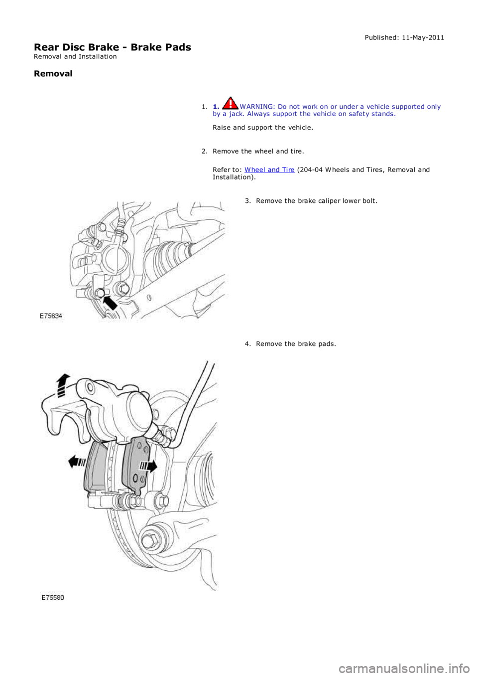
Remove t he brake caliper lower bolt .3.
Remove t he brake pads.4.
Page 440 of 3229
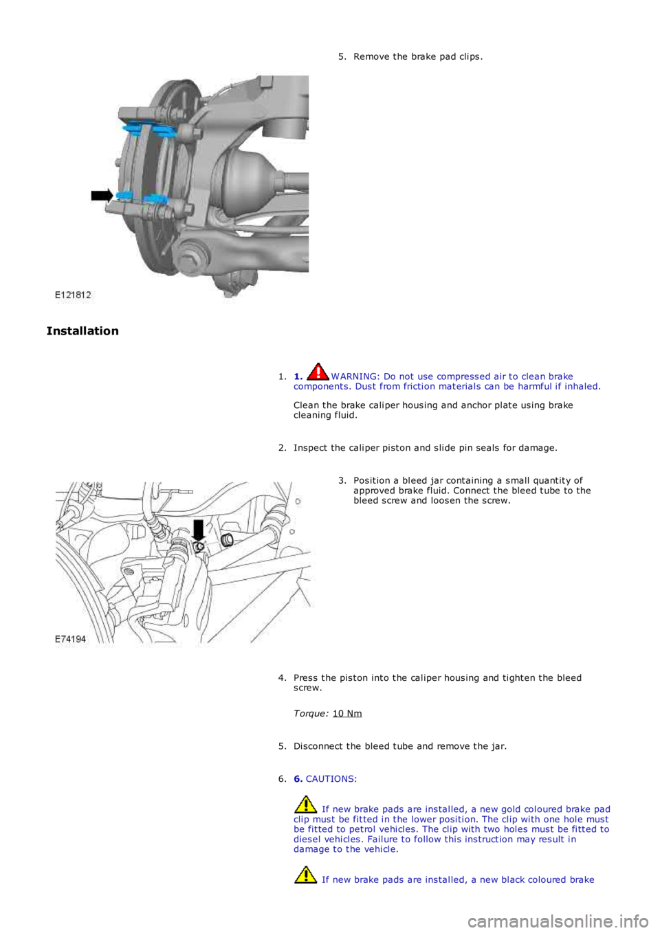
Remove t he brake pad cli ps .
5.
Installation 1. W ARNING: Do not use compress ed air t o clean brake
component s. Dus t from fricti on mat erial s can be harmful i f inhaled.
Clean t he brake cali per hous ing and anchor pl at e us ing brake
cleaning fluid.
1.
Inspect the cali per pi st on and s li de pin seals for damage.
2. Pos it ion a bl eed jar cont aining a s mall quant it y of
approved brake fluid. Connect t he bleed t ube to the
bleed s crew and loos en the s crew.
3.
Pres s t he pis t on int o t he cal iper hous ing and ti ght en t he bleed
s crew.
T orque: 10 Nm 4.
Di sconnect t he bleed t ube and remove t he jar.
5.
6. CAUTIONS: If new brake pads are ins tal led, a new gold col oured brake pad
cli p mus t be fit ted i n t he lower posi ti on. The cl ip wi th one hol e mus t
be fit ted to pet rol vehi cl es. The cl ip wi th two hol es mus t be fi tt ed t o
dies el vehi cl es . Fail ure t o follow thi s ins truct ion may res ult i n
damage t o t he vehi cl e. If new brake pads are ins tal led, a new bl ack coloured brake
6.