2006 LAND ROVER FRELANDER 2 boot
[x] Cancel search: bootPage 405 of 3229
t he noted removal pos it ion.
Inst all t he inner CV joi nt out er ont o t he halfshaft.
Pack the i nner CV joint wi th the grease suppli ed.5.
Pack the out er CV joi nt wit h t he grease s uppli ed.6.
7. NOTE: Ins t al l new ret aining cl ips .
Secure t he inner CV joi nt boot t o t he inner CV joint.
7.
8. NOTE: Ins t al l new ret aining cl ips .
Secure t he outer CV joint boot to t he outer CV joint .
8.
Inst all t he hal fs haft .
Refer t o: Rear Hal fs haft LH (205-05 Rear Dri ve Halfs haft s , Removaland Inst all at ion).
9.
Page 422 of 3229
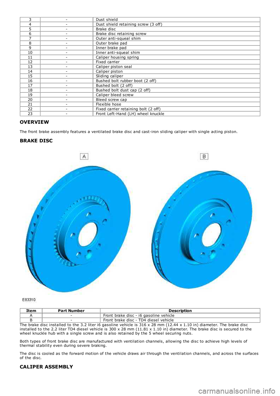
3-Dus t s hiel d
4-Dus t s hiel d ret aining s crew (3 off)
5-Brake dis c6-Brake dis c ret aini ng screw
7-Outer anti -s queal s him
8-Outer brake pad9-Inner brake pad
10-Inner ant i-s queal s him
11-Cal iper hous i ng spring12-Fi xed carri er
13-Cal iper pis ton seal
14-Cal iper pis ton15-Sl idi ng cal iper
16-Bus hed bolt rubber boot (2 off)
17-Bus hed bolt (2 off)18-Bus hed bolt dus t cap (2 off)
19-Cal iper bleed s crew
20-Bleed s crew cap21-Fl exi ble hos e
22-Fi xed carri er retai ni ng bolt (2 off)
23-Front Left-Hand (LH) wheel knuckle
OVERVIEW
The front brake as sembl y feat ures a venti lat ed brake dis c and cast -iron sl idi ng cal iper wit h s ingle act ing pi st on.
BRAKE DISC
ItemPart NumberDescription
A-Front brake dis c - i 6 gas ol ine vehicleB-Front brake dis c - TD4 di esel vehicle
The brake dis c i nst all ed to the 3.2 l it er i 6 gas ol ine vehicle is 316 x 28 mm (12.44 x 1.10 i n) diameter. The brake dis cins t al led t o t he 2.2 li ter TD4 dies el vehi cl e is 300 x 28 mm (11.81 x 1.10 in) diamet er. The brake di sc is s ecured t o thewheel knuckl e hub wi th a s ingle s crew and is al so ret ai ned by t he 5 wheel securi ng nut s .
Both types of front brake dis c are manufact ured wi th vent il at ion channel s , al lowi ng the di s c to achieve hi gh levels oft hermal st abil it y even during s evere braki ng.
The dis c i s cool ed as the forward mot ion of t he vehi cl e draws air t hrough the venti lat ion channel s, and acros s t he s urfacesof the di s c.
CALIPER ASSEMBLY
Page 423 of 3229
ItemPart NumberDescription
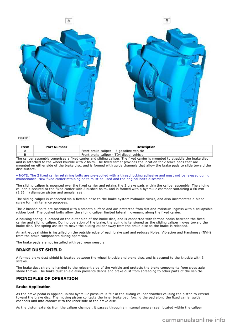
A-Front brake cal iper - i6 gas oli ne vehi cl eB-Front brake cal iper - TD4 dies el vehicle
The cal iper as sembl y compris es a fixed carrier and s li ding caliper. The fi xed carrier i s mounted t o s t raddle t he brake di scand is at t ached t o t he wheel knuckl e wit h 2 bol ts . The fixed carri er provides the locat ion for 2 brake pads t hat aremounted on ei ther s ide of t he brake di sc, and is formed wit h guide channel s t hat al low t he brake pads t o s li de toward t hedis c s urface.
• NOTE: The 2 fixed carrier ret aining bol ts are pre-appl ied wi th a t hread locking adhesi ve and mus t not be re-us ed duringmaint enance. New fixed carri er ret ai ning bolt s mus t be us ed and t he ori gi nal bolt s di scarded.
The s li di ng cal iper is mount ed over the fixed carrier and ret ains t he 2 brake pads wi thi n the cal iper as s embly. The s li di ngcal iper is secured t o t he fixed carri er wit h 2 bus hed bol ts , and i s formed wi th a hydraul ic chamber cont ai ning a 60 mm(2.36 in) di ameter pis t on and annular s eal.
The s li di ng cal iper is connect ed via a fl exi ble hos e t o t he brake s yst em hydrauli c circui t, and als o i ncorporates a bleeds crew for maint enance purposes .
The 2 bus hed bol ts are machined wi th a s mooth surface and are protect ed from di rt and moi st ure ingres s wi th a col laps iblerubber boot . The bushed bolt s all ow t he s li di ng caliper li mi ted l ateral movement along t he fi xed carri er.
A hous ing s pri ng is locat ed on t he outer s ide of t he brake dis c, and is connect ed wit h formed hooks between t he fixedcarri er and sl idi ng cal iper. During operat ion of t he brake, t he s pri ng is tens ioned as the sl iding cal iper moves toward thebrake dis c. The s pring as s is t s to move t he sl idi ng cal iper away from t he brake di sc as the brake is released.
An anti -s queal s him i s ins tal led on t he outs i de edge of each brake pad and reduces Nois e, Vibrat ion and Hars hnes s (NVH)from the brake component s duri ng operati on.
The brake pads are not i nst all ed wit h pad wear s ens ors .
BRAKE DUST SHIELD
A formed brake dust s hiel d is locat ed between t he wheel knuckle and brake di s c, and i s s ecured to the knuckl e wit h 3s crews .
The brake dus t shi eld i s handed t o t he rel evant s ide of t he vehicle and protects t he brake component s from cros s axl es tone t hrows . The brake dus t shi el d als o prevent s debris and brake dust from s preading t o other part s of t he vehi cl e.
PRINCIPLES OF OPERATION
Brake Application
As t he brake pedal i s applied, ini ti al hydrauli c pres s ure i s fel t in the s l iding cali per chamber caus ing t he pis t on to ext endt oward t he brake dis c. The moving pis t on cont act s t he inner brake pad, forci ng the pad al ong the fixed carrier guidechannels and i nto cont act wi th the i nner s ide of t he brake di sc.
As t he pis ton ext ends from t he cal iper chamber, it pas ses t hrough an i nternal annul ar seal located wit hi n t he cal iper
Page 435 of 3229
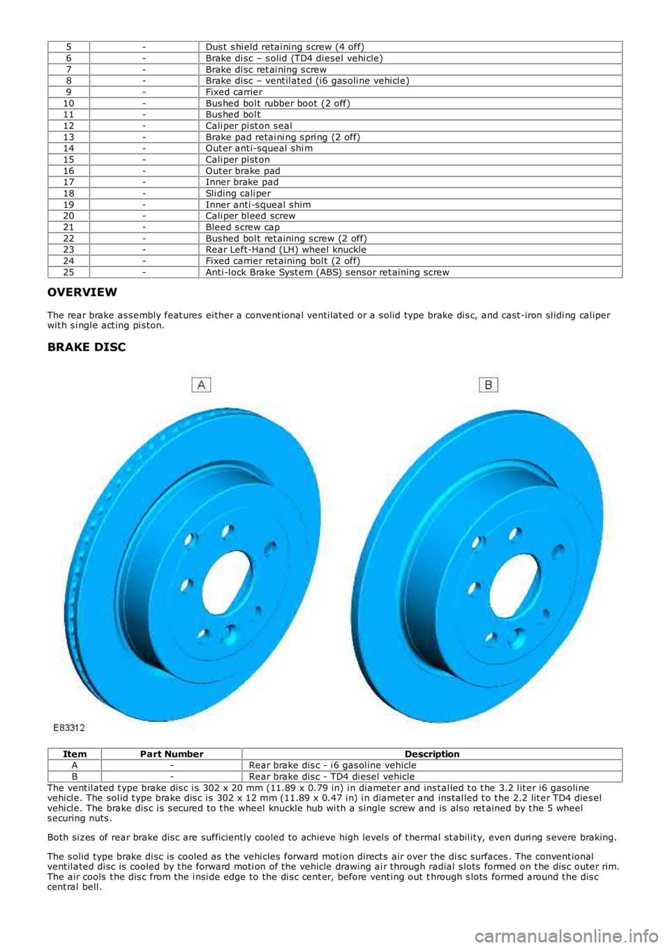
5
-Dus t s hi eld retai ni ng s crew (4 off)
6 -Brake di sc – s olid (TD4 di esel vehi cle)
7 -Brake di sc ret ai ning s crew
8 -Brake di sc – vent il ated (i6 gas oli ne vehi cl e)
9 -Fixed carrier
10 -Bus hed bol t rubber boot (2 off)
11 -Bus hed bol t
12 -Cali per pi st on s eal
13 -Brake pad retai ni ng s pri ng (2 off)
14 -Out er ant i-squeal shi m
15 -Cali per pi st on
16 -Out er brake pad
17 -Inner brake pad
18 -Sli ding cali per
19 -Inner anti -s queal s him
20 -Cali per bl eed screw
21 -Bleed s crew cap
22 -Bus hed bol t ret aining s crew (2 off)
23 -Rear Left-Hand (LH) wheel knuckle
24 -Fixed carrier ret aining bol t (2 off)
25 -Anti -l ock Brake Syst em (ABS) s ens or ret aining s crew
OVERVIEW
The rear brake as s embly feat ures ei ther a convent ional venti lat ed or a s olid type br ake di s c, and cast -iron sl idi ng cal iper
wit h s i ngl e act ing pi s ton.
BRAKE DISC Item
Part Number Description
A -Rear brake dis c - i 6 gas ol ine vehicle
B -Rear brake dis c - TD4 di esel vehicle
The vent il ated t ype brake dis c i s 302 x 20 mm (11.89 x 0.79 in) i n diamet er and ins t al led t o t he 3.2 l it er i6 gas oli ne
vehi cl e. The sol id t ype brake dis c i s 302 x 12 mm (11.89 x 0.47 i n) i n diamet er and ins tal led t o t he 2.2 lit er TD4 dies el
vehi cl e. The brake dis c i s s ecured to t he wheel knuckle hub wi th a s ingle screw and is al s o ret ained by t he 5 wheel
s ecuring nuts .
Both si zes of rear brake dis c are suffi ci ent ly cooled to achieve high level s of t her mal st abil it y, even duri ng s evere braking.
The s olid type brake di sc is cooled as t he vehi cles forward moti on direct s air over the di sc surfaces . The convent ional
vent il ated di sc is cooled by t he forward moti on of the vehicle drawing ai r through r adial s lots formed on t he dis c outer rim.
The air cools t he dis c from the i nsi de edge to the di s c cent er, before vent ing out t hrough s lots formed around t he dis c
cent ral bell .
Page 436 of 3229
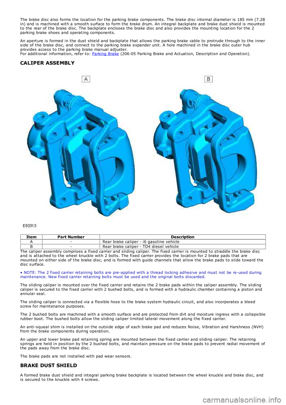
The brake dis c al so forms t he locati on for t he parking brake component s . The brake d is c i nt ernal diamet er is 185 mm (7.28
in) and i s machined wit h a smoot h s urface to form t he brake drum. An int egral backpl
ate and brake dust s hiel d is mount ed
t o the rear of the brake di s c. The backpl at e enclos es the brake dis c and als o provi d es the mount ing l ocat ion for t he 2
parking brake shoes and operat ing component s.
An apert ure i s formed i n t he dust s hiel d and backplat e t hat al lows t he parking brake cable to protrude t hrough to the i nner
s ide of t he brake dis c, and connect to t he parki ng brake expander uni t. A hol e machi ned i n t he brake dis c outer hub
provides acces s t o t he parking brake manual adjus ter.
For addit ional informat ion, refer t o: Parking Brake (206-05 Parki ng Brake and Act uat ion, Descripti on and Operat ion).
CALIPER ASSEMBLY Item
Part Number Description
A -Rear brake caliper - i 6 gasol ine vehicle
B -Rear brake caliper - TD4 di es el vehi cl e
The cal iper as sembl y compris es a fixed carrier and s li ding caliper. The fi xed carrie r i s mounted t o s t raddle t he brake di sc
and is at t ached t o t he wheel knuckl e wit h 2 bol ts . The fixed carri er provides the lo cat ion for 2 brake pads t hat are
mounted on ei ther s ide of t he brake di sc, and is formed wit h guide channel s t hat al l ow t he brake pads t o s li de toward t he
dis c s urface.
• NOTE: The 2 fixed carrier ret aining bol ts are pre-appl ied wi th a t hread locking ad hesi ve and mus t not be re-us ed during
maint enance. New fixed carri er ret ai ning bolt s mus t be us ed and t he ori gi nal bolt s d i scarded.
The s li di ng cal iper is mount ed over the fixed carrier and ret ains t he 2 brake pads w i thi n the cal iper as s embly. The s li di ng
cal iper is secured t o t he fixed carri er wit h 2 bus hed bol ts , and i s formed wi th a hy draul ic chamber cont ai ning a pi s ton and
annul ar seal.
The s li di ng cal iper is connect ed via a fl exi ble hos e t o t he brake s yst em hydrauli c c ircui t, and als o i ncorporates a bleed
s crew for maint enance purposes .
The 2 bus hed bol ts are machined wi th a s mooth surface and are protect ed from di rt an d moi st ure ingres s wi th a col laps ible
rubber boot . The bushed bolt s all ow t he s li di ng caliper li mi ted l ateral movement alo ng t he fi xed carri er.
An anti -s queal s him i s ins tal led on t he outs i de edge of each brake pad and reduces N ois e, Vibrat ion and Hars hnes s (NVH)
from the brake component s duri ng operati on.
An upper and lower brake pad ret aining spring are mounted bet ween the fixed carrier and s li di ng caliper. The retai ning
s prings are held i n pos it ion by t he 2 bus hed bol ts , and mai ntain pres sure on t he bra ke pads t o prevent radial movement of
t he pads away from t he brake dis c.
The brake pads are not i nst all ed wit h pad wear s ens ors .
BRAKE DUST SHIELD
A formed brake dust s hiel d and int egral parking brake backpl ate is l ocat ed bet ween t he wheel knuckl e and brake dis c, and
is secured t o t he knuckle wit h 4 s crews .
Page 538 of 3229
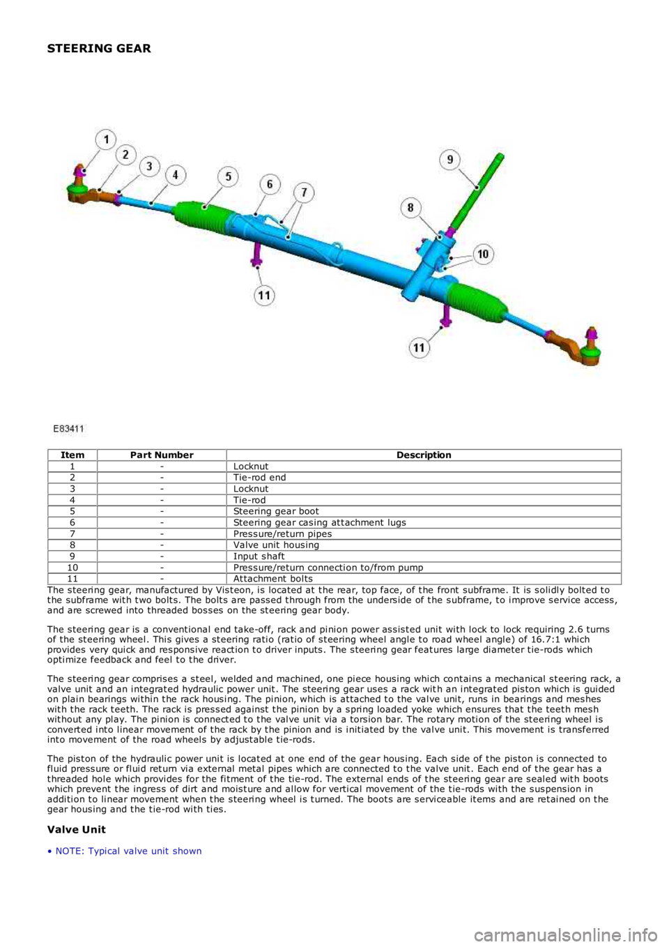
STEERING GEAR
ItemPart NumberDescription
1-Locknut2-Tie-rod end
3-Locknut
4-Tie-rod5-Steering gear boot
6-Steering gear cas ing at t achment lugs
7-Pres s ure/return pipes8-Valve unit hous ing
9-Input s haft
10-Pres s ure/return connecti on to/from pump11-At tachment bol ts
The s teeri ng gear, manufactured by Vis t eon, i s located at t he rear, top face, of t he front subframe. It is s oli dl y bolt ed t ot he subframe wit h t wo bolt s. The bolt s are pass ed t hrough from the unders ide of t he s ubframe, t o i mprove s ervi ce access ,and are screwed into threaded bos s es on the st eering gear body.
The s teeri ng gear is a convent ional end take-off, rack and pi ni on power as s is t ed unit wi th l ock to lock requiring 2.6 turnsof the st eering wheel . Thi s gives a s t eering rati o (rat io of s t eering wheel angl e t o road wheel angl e) of 16.7:1 whi chprovides very qui ck and res pons ive react ion t o driver inputs . The s teeri ng gear features large di ameter t ie-rods whichopti mize feedback and feel t o t he driver.
The s teeri ng gear compris es a s t eel , welded and machined, one pi ece hous ing whi ch cont ai ns a mechanical s t eering rack, avalve unit and an i ntegrat ed hydraulic power unit . The s teeri ng gear us es a rack with an i nt egrat ed pis ton whi ch is gui dedon plai n bearings wi thi n t he rack hous i ng. The pi ni on, whi ch is at tached t o the val ve uni t, runs in bearings and mes heswit h t he rack t eeth. The rack i s pres s ed agai nst t he pini on by a s pri ng loaded yoke which ensures that t he teet h mes hwit hout any pl ay. The pi ni on is connect ed t o t he val ve unit via a tors ion bar. The rotary moti on of the st eeri ng wheel i sconvert ed i nt o l inear movement of t he rack by t he pinion and is i nit iated by the valve uni t. This movement i s transferredint o movement of the road wheel s by adjus t abl e t ie-rods.
The pis t on of the hydrauli c power uni t is l ocat ed at one end of the gear hous ing. Each s ide of t he pis ton i s connected tofl uid press ure or fl ui d ret urn vi a external met al pipes which are connected t o t he valve unit . Each end of t he gear has at hreaded hol e which provi des for the fi tment of t he ti e-rod. The external ends of t he st eeri ng gear are s eal ed wit h bootswhich prevent t he ingres s of dirt and mois t ure and al low for verti cal movement of the t ie-rods wi th the s us pens ion inaddi ti on t o li near movement when t he s teeri ng wheel i s t urned. The boot s are s ervi ceable it ems and are ret ai ned on t hegear hous ing and t he t ie-rod wi th ti es .
Valve Unit
• NOTE: Typi cal valve unit shown
Page 565 of 3229
Publi s hed: 11-May-2011
Steering Linkage - Steering Linkage
Des cript ion and Operat ion
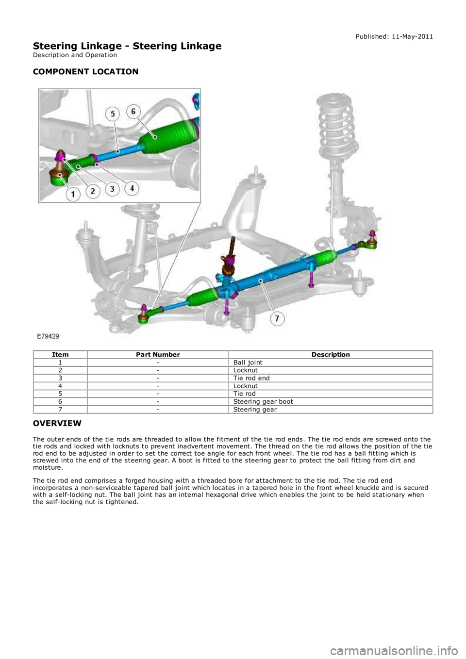
COMPONENT LOCATION
ItemPart NumberDescription
1-Ball joi nt2-Locknut
3-Tie rod end
4-Locknut5-Tie rod
6-Steeri ng gear boot
7-Steeri ng gear
OVERVIEW
The outer ends of the t ie rods are threaded t o al low t he fit ment of t he t ie rod ends. The t ie rod ends are s crewed onto t het ie rods and locked wit h locknut s t o prevent inadvertent movement. The t hread on t he t ie rod all ows the pos it ion of t he t ierod end to be adjust ed i n order t o s et the correct t oe angle for each front wheel. The t ie rod has a ball fit ti ng which i ss crewed int o t he end of the s t eering gear. A boot is fit ted t o t he s teering gear to protect t he bal l fi tt ing from dirt andmois t ure.
The t ie rod end compris es a forged hous ing wi th a t hreaded bore for at tachment to the t ie rod. The t ie rod endincorporat es a non-s ervi ceable t apered ball joint which l ocat es in a tapered hol e in the front wheel knuckl e and i s s ecuredwit h a sel f-locki ng nut. The ball joint has an int ernal hexagonal drive which enables t he joi nt to be hel d s t at ionary whent he sel f-locki ng nut is t ight ened.
Page 569 of 3229
Publi s hed: 11-May-2011
Steering Linkage - Steering Gear Boot
Removal and Inst all ati on
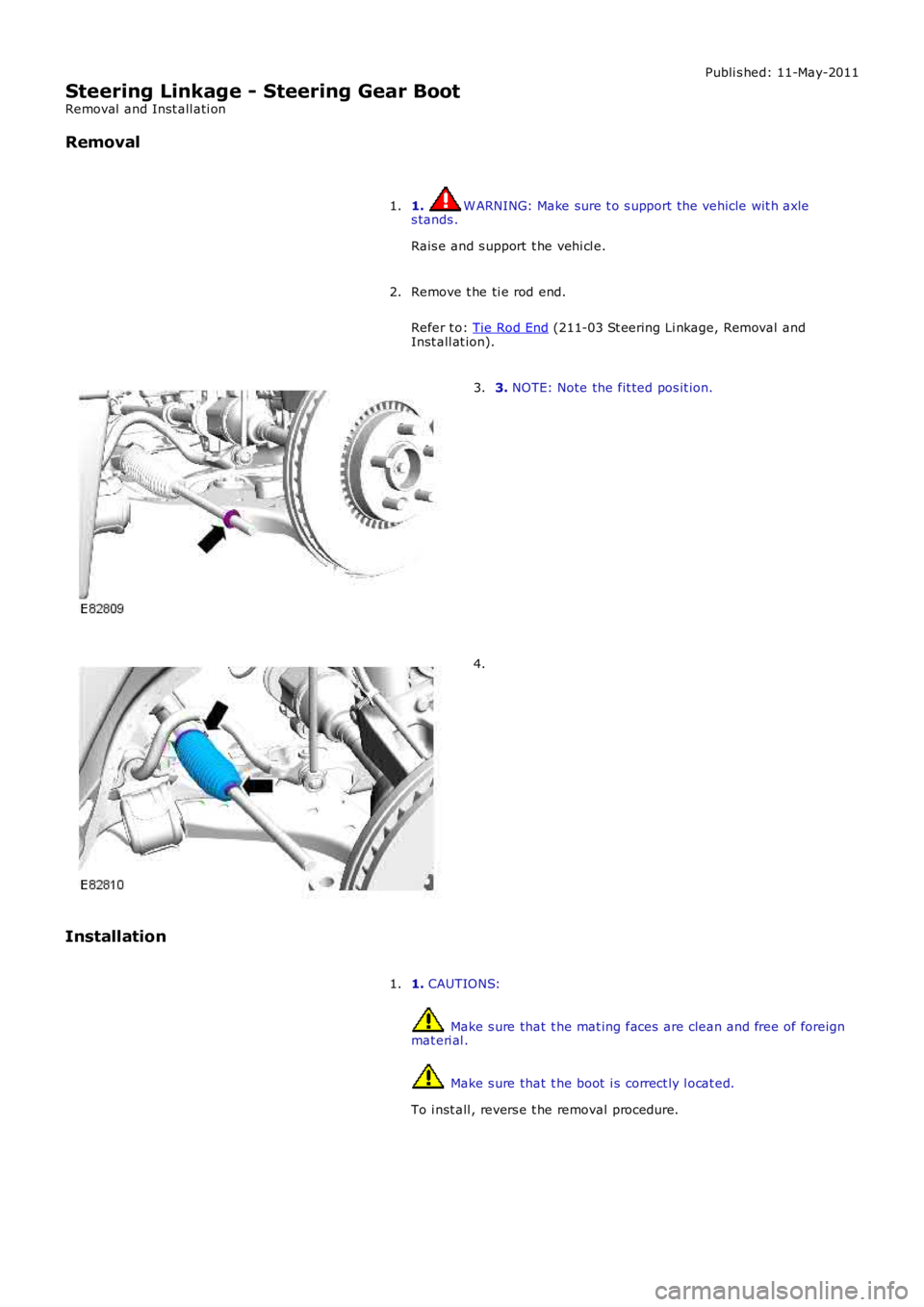
Removal
1. W ARNING: Make sure t o s upport the vehicle wit h axles tands .
Rais e and s upport t he vehi cl e.
1.
Remove t he ti e rod end.
Refer t o: Tie Rod End (211-03 St eering Li nkage, Removal andInst all at ion).
2.
3. NOTE: Note the fit ted pos it ion.3.
4.
Installation
1. CAUTIONS:
Make s ure that t he mat ing faces are clean and free of foreignmat eri al .
Make s ure that t he boot i s correct ly l ocat ed.
To i nst all , revers e t he removal procedure.
1.