2006 LAND ROVER FRELANDER 2 ECO mode
[x] Cancel search: ECO modePage 524 of 3229
s peed control '+' and '-' but t ons (dependant on vehi cl e s peci fi cat ion). The HDC Target speed wi ll als o vary depending ont he Terrai n Respons e™ mode sel ect ed.
Duri ng changes of target s peed, the ABS modul e li mit s vehicle decelerat ion and accelerat ion t o -0.5 met ers per s econd
s quared (m/s2) (-1.64 feet per s econd squared (ft/s2)); and +0.5 m/s2 (+1.64 ft/s2) res pect ively.
To provide a s afe t rans it ion from acti ve braking t o brakes off, the ABS module i nvokes a fade out st rat egy that graduall yrel eas es t he braking effort during act ive braking. The fade out s t rat egy occurs i f any of t he fol lowi ng condit ions i s detectedduri ng act ive braki ng:
HDC i s s elected off us i ng the HDC s wit ch.Failure of a component us ed by HDC, but not crit ical t o fade out funct ion.Accelerator pedal pres s ed when t rans mis s ion i s i n neut ral .Brakes overheat .
If fade out is i nvoked becaus e of HDC de-s el ect ion or component failure, the HDC functi on is cancel led by t he ABS module.If fade out is i nvoked becaus e t he accelerator pedal i s pres s ed wit h t he t ransmis s ion i n neut ral , or because of brakeoverheat , t he HDC funct ion remains in s tandby and res umes operati on when t he accelerat or pedal is releas ed or the brakeshave cooled.
The fade out s t rategy i ncreas es t he t arget speed at a cons tant accelerati on rat e of 0.5 m/s2 (1.64 ft/s2), unti l themaximum t arget speed i s reached, or unti l no act ive braki ng is required for 0.5 second. If t he accelerat or pedal is
posi ti oned wit hin t he range t hat infl uences t arget s peed, the accelerat ion rate is increas ed t o 1.0 m/s2 (3.3 ft /s2).
W hen fade out is i nvoked becaus e of component fai lure, a warning chime is sounded and the HDC informat ion i ndi cat orlamp is ext inguis hed. The HDC warning i ndicat or lamp is t hen il lumi nat ed (on low-li ne ins trument cl ust er), or a mes s ageadvi s ing of t he fault i s dis played in the mess age cent er (on hi gh-l ine i ns t rument clus ter).
For addit ional informat ion, refer t o:
Ins trument Clus ter (413-01 Ins t rument Clus t er, Descripti on and Operat ion),Informat ion and Mes s age Cent er (413-08 Informati on and Mes sage Cent er, Descripti on and Operat ion).
W hen fade out is i nvoked becaus e of brake overheat, on vehicles wi th the hi gh-li ne ins t rument clus ter, a mes sage advis ingt hat HDC is t emporarily unavail abl e is di s pl ayed. On vehicles wit h t he low-line ins trument cl us t er, t he HDC warningindicat or l amp flas hes . At t he end of fade out, t he HDC informati on indicat or flas hes. The flas hing warni ng and informat ionindicat or l amps, and/or di spl ayed mes s age cont inue whi le HDC remai ns sel ect ed, unt il t he brakes have cooled.
For addit ional informat ion, refer t o:
Ins trument Clus ter (413-01 Ins t rument Clus t er, Descripti on and Operat ion),Informat ion and Mes s age Cent er (413-08 Informati on and Mes sage Cent er, Descripti on and Operat ion).
To monit or for brake overheat, t he ABS modul e monit ors t he amount of braking acti vi ty and, from thi s, es ti mat es thet emperature of each brake. If the es t imat ed temperature of any brake exceeds a pres et li mit , t he ABS module i nvokes t hefade out s t rategy. Aft er the fade out cycle, t he HDC funct ion i s re-enabl ed when the ABS modul e es ti mates that all of thebrake t emperatures are at l ess than 64% of the preset t emperat ure l imi t.
Roll Stability Control
The RSC funct ion us es the brakes and the engine t o at tempt t o rest ore vehicle s tabilit y, i f the vehicle is forced i nt o ahars h maneuver t hat ri sks i t ti pping over.
The ABS module monit ors dri ver i nput s and vehicle behavior usi ng various powert rai n s ignals and t he i nput s from thewheel s peed s ens ors, t he s teering angle s ens or, the roll rate sens or, yaw rate and lateral accel erat ion s ensors. Thes einputs are compared wit h modeled behavi or and, if t he vehicle behavior reaches a given ris k level, t he ABS module cut st he engi ne power, or brakes one or more wheels suffi ci ent ly to al low the vehicle to regain s t abi li ty and hel p the driverremai n i n cont rol .
W hi le t he i gni ti on is energi zed, RSC i s permanentl y enabl ed even if t he DSC functi on is sel ect ed off.
Terrain Response™ System Integration
The Terrai n Res pons e™ funct ion integrat es t he ABS and other vehicle s ys tem cont rol modules t o as si s t the vehicle whendri vi ng off-road or during di fficult s urface condit ions . Terrai n Respons e is act ivated when the rotary cont rol s wit ch is s et t oa Terrain Res ponse special program.
W hen a Terrai n Respons e s peci al program i s acti vat ed, t he ABS module along wi th ot her vehicle s ys t em control modul eswil l operate in accordance wi th programmed software maps . The s oftware maps al low t he ABS s ys tem to functi on wit h at hreshol d that wi ll as si s t the s elected Terrai n Respons e s pecial program.For addit ional informat ion, refer t o: Ride and Handli ng Opti mizat ion (204-06 Ride and Handli ng Opt imi zat ion, Descripti onand Operat ion).
Page 587 of 3229
11-Int egrated audio modul e
12-Int egrated control modul e
PRINCIPLES OF OPERATION
Windshield Wiper Switch
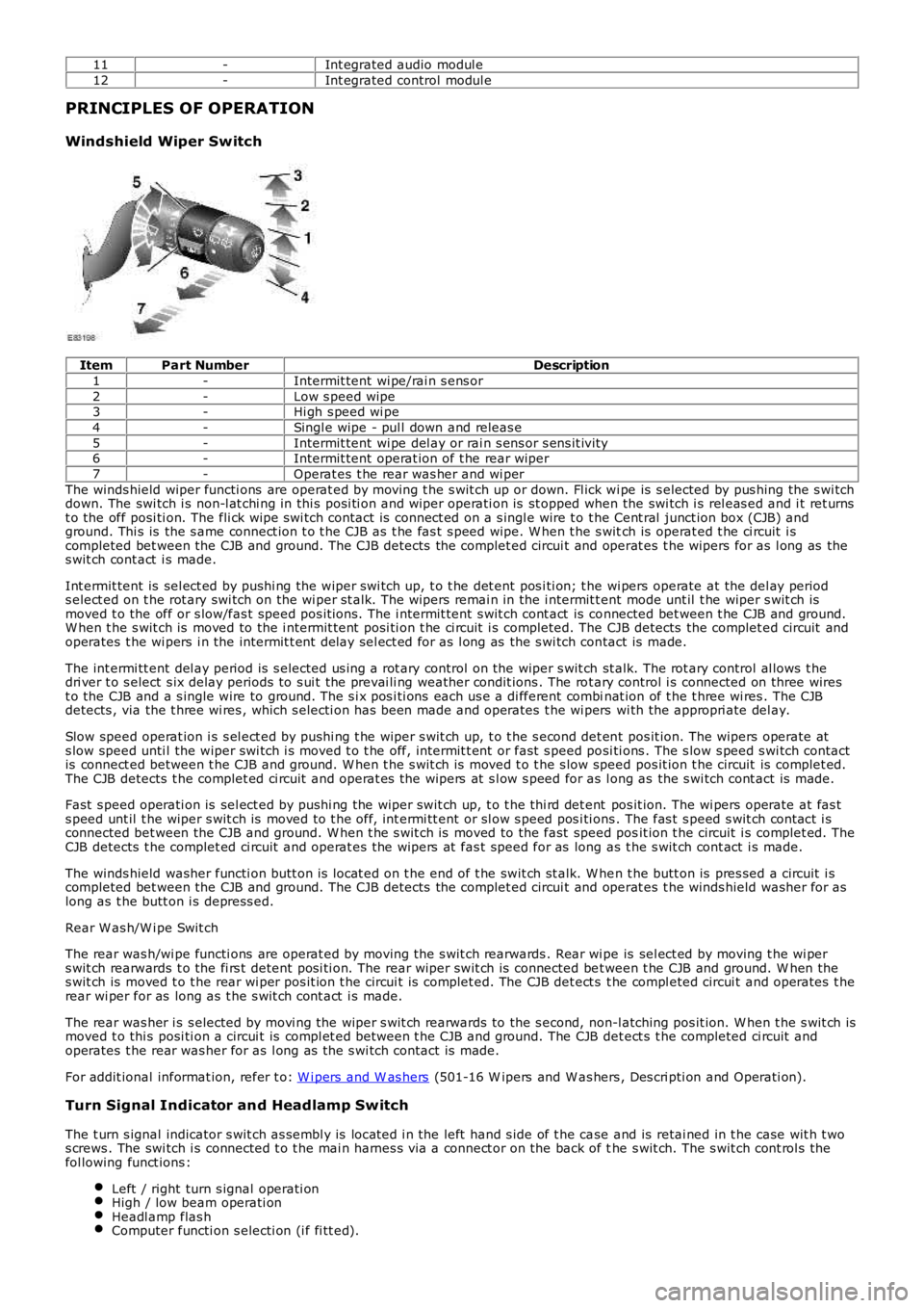
ItemPart NumberDescription
1-Intermit tent wi pe/rai n s ens or
2-Low s peed wipe3-Hi gh s peed wi pe
4-Singl e wipe - pul l down and releas e
5-Intermit tent wi pe del ay or rai n s ens or s ens it ivi ty6-Intermit tent operat ion of t he rear wiper
7-Operat es t he rear was her and wi per
The winds hield wiper functi ons are operat ed by moving t he s wit ch up or down. Fl ick wi pe is s elected by pus hing the s wi tchdown. The swi tch i s non-l at chi ng in thi s posi ti on and wiper operati on is st opped when the swi tch i s rel eas ed and i t ret urnst o the off posi ti on. The fli ck wipe s wi tch contact is connect ed on a s ingl e wire t o t he Cent ral junct ion box (CJB) andground. Thi s is the s ame connect ion t o t he CJB as t he fas t s peed wipe. W hen t he s witch is operat ed t he ci rcuit i scompleted bet ween the CJB and ground. The CJB detects the complet ed circui t and operat es t he wipers for as l ong as thes wit ch cont act i s made.
Int ermit tent is sel ect ed by pushi ng the wiper swi tch up, t o t he det ent pos i ti on; t he wi pers operate at the del ay periods elect ed on t he rot ary swi tch on the wi per st alk. The wipers remai n in the i ntermit tent mode unt il t he wiper s wit ch ismoved t o the off or s low/fas t speed pos it ions. The i ntermit tent s wit ch cont act is connected bet ween t he CJB and ground.W hen t he s wit ch is moved to the i ntermit tent posi ti on t he ci rcuit i s completed. The CJB detects the complet ed circuit andoperates t he wi pers i n the intermit t ent delay sel ect ed for as l ong as the s wi tch contact is made.
The int ermi tt ent del ay period is s elected us i ng a rot ary control on the wiper s wit ch st alk. The rot ary control al lows t hedri ver t o s elect s ix delay periods to s ui t the prevai li ng weather condit ions . The rot ary control i s connected on three wirest o the CJB and a s ingle wire to ground. The s i x pos i ti ons each us e a di fferent combinat ion of t he t hree wi res . The CJBdetects , via the t hree wi res , which s electi on has been made and operates t he wi pers wi th the appropri ate del ay.
Slow speed operat ion i s s el ect ed by pus hi ng t he wiper s wit ch up, t o t he s econd det ent pos it ion. The wipers operate ats low speed unti l the wiper swi tch i s moved t o t he off, intermit t ent or fast s peed posi ti ons . The s low s peed s wi tch contactis connect ed between t he CJB and ground. W hen t he s wit ch is moved t o t he s low speed pos it ion t he circuit is complet ed.The CJB detects t he complet ed ci rcuit and operat es the wipers at s l ow s peed for as long as the s wi tch cont act is made.
Fast s peed operati on is sel ect ed by pushi ng the wiper swit ch up, t o t he thi rd det ent pos it ion. The wi pers operate at fas ts peed unt il t he wiper s wit ch is moved to t he off, int ermi tt ent or sl ow s peed pos i ti ons . The fas t s peed s wit ch cont act i sconnected bet ween the CJB and ground. W hen t he s wit ch is moved to the fast speed posit ion t he circuit i s complet ed. TheCJB detects t he complet ed ci rcuit and operat es the wipers at fas t speed for as long as t he s wit ch cont act i s made.
The winds hield washer functi on butt on is locat ed on t he end of t he swit ch st alk. W hen t he butt on is pres sed a circuit i scompleted bet ween the CJB and ground. The CJB detects the complet ed circui t and operat es t he winds hield washer for aslong as t he butt on i s depress ed.
Rear W as h/W i pe Swit ch
The rear was h/wi pe functi ons are operat ed by moving t he s wit ch rearwards . Rear wi pe is sel ect ed by moving t he wi pers wit ch rearwards t o the fi rs t detent posi ti on. The rear wiper swit ch is connected bet ween t he CJB and ground. W hen thes wit ch is moved t o t he rear wi per pos it ion t he circui t is complet ed. The CJB det ect s t he compl eted circui t and operates t herear wi per for as long as t he s wit ch cont act i s made.
The rear was her i s s elected by movi ng the wiper s wit ch rearwards to the s econd, non-l atching pos it ion. W hen t he s wit ch ismoved t o thi s posi ti on a circui t is compl et ed between t he CJB and ground. The CJB det ect s t he completed ci rcuit andoperates t he rear was her for as l ong as the s wi tch contact is made.
For addit ional informat ion, refer t o: W i pers and W as hers (501-16 W ipers and W as hers , Des cri pti on and Operati on).
Turn Signal Indicator and Headlamp Switch
The t urn s ignal indicator s wit ch as sembl y is locat ed i n the left hand s ide of t he case and is retai ned in t he case wit h t wos crews . The swi tch i s connected t o t he mai n harnes s via a connect or on the back of the s wit ch. The s wit ch cont rol s thefol lowing funct ions :
Left / right turn s ignal operati onHigh / low beam operati onHeadl amp flas hComputer functi on s electi on (i f fi tt ed).
Page 603 of 3229
Publi s hed: 23-Aug-2011
Engine - I6 3.2L Petrol -
Lubricants, Fluids, Sealers and AdhesivesDescriptionLand Rover Part No.
Cam cover to cyli nder head jointLR006801 (Loct it e 510)
Bedplate to oi l s umpSTC50550Block t o bedpl ateSTC50550
Engine oil - NAS, Mi ddl e Eas t and Nort h Africa Models5W /30 - ACEA A1 + ILSAC GF-3 or ILSAC GF-3*
Engine oil - ROW Models0W /30 - ACEA A5/B5The recommended oil change i nterval for ILSAC GF-3 is 5000 mi les .
C apacities
ItemCapacity (liters/pints/USquarts)
Dry fi ll i ncludi ng fi lt er9.3/16.4/9.8
Service fil l - includes fi lt er7.7/13.6/8.1Amount of oil required t o bri ng the level from the lower to the upper mark on thedips t ick0.8/1.4/0.9
General Specification
ItemSpecificationType3.2 li ter, inli ne 6 nat urall y aspi rat ed pet rol engine, twi n overheadcams haft s, 4 val ves per cylinderCyli nder arrangementInli ne 6
Cyli nder numberi ng1-6 from front of engine
Bore - nominal84.0 mm (3.307 in)St roke96.0 mm (3.779 in)
Capaci ty3192 cm³ (195.8 i n³)
Firing order1 - 5 - 3 - 6 - 2 - 4Compres s ion rati o10.8:1
Di recti on of rotat ionCl ockwis e from front of engi ne
Maximum power171 kW (230 hp) @ 6300rpmMaximum t orque317 Nm (234 lb-ft ) @ 3200rpm
Engine oil pressure*:
At 800 rev/min1.03 bar/103 kPa/15 lb/in²At 4000 rev/min3.45 bar/345 kPa/50 lb/in²
Oil pump
Oi l pump to cranks haft clearance0.087mm ±0.022 mm (0.00343 i n ± 0.000866 i n)Maximum permissible cylinder head w arp:
Over head length0.05 mm (0.00196 i n)
Over head widt h0.03 mm (0.00118 i n)Cyli nder head height149.4 mm ± 0.15 mm (5.882 in ± 0.0059 i n)
Maximum permi s si ble amount t o be removedduri ng s ki mmi ng0.3 mm (0.0118 in)
Main bearing journals:
Number7
Di amet er s tandard65 mm + 0.004 - 0.015 mm (2.55 in + 0.000157 - 0.000590 in)Maximum diamet er variat ion0.006 mm (0.000236 in)
Big end journals:
Di amet er s tandard50 mm + 0.004 - 0.015 mm (1.96 in + 0.000157 - 0.000590 in)Maximum diamet er variat ion0.01 mm (0.000393 i n)
Camshaft:
Number of bearings7 per cams haftT appets+:
InletHydrauli c
Exhaus t +GradedValves:
Valve clearance - Exhaus t0.45mm ±0.05 mm (0.0177 in ± 0.00196 in)
Lengt h - i nlet valve106.19 mm ± 0.07 mm (4.18 in ± 0.0275 i n)Lengt h - exhaus t valve129.96 mm ± 0.07 mm (5.12 in ± 0.0275 i n)
Seat angl e45° ± 0.01°
Head diamet er - inlet valve33 mm ± 0.15 mm (1.29 in ± 0.0590 i n)Head diamet er - exhaus t val ve28 mm ± 0.15 mm (1.10 in ± 0.0590 i n)
St em diamet er - inlet valve5.97 mm + 0 -.015 mm (0.235 in + 0 -000590 i n)
St em diamet er - exhaus t val ve5.962 mm +0 -0.007 mm (0.234 in +0 -0.000275 i n)St em t o guide clearance - i nlet val ve50-70 µm
St em t o guide clearance - exhaus t valve50-70 µm
Valve springs:TypeConical
Lengt h (free)45 mm (1.77 in)
* Prior to checking the engine oil pressure, a road test of 6 miles (10 kilometres) must be carried out. Do notattempt to attain normal engine operating temperature by allowing the engine to idle.
+ T here are 50 different thicknesses of graded tappet available ranging from 2.950mm to 3.685 mm (0.116 in to0.145 in) rising in increments of 0.015 mm (0.0005 in).
Torque Specifications
Page 1027 of 3229
At low engi ne s peed t he volume of exhaust gas l eavi ng the engine is l ow. The vanes are moved toward the cl osed pos it iont o direct t he exhaus t gas fl ow t o t he out s ide edge of t he turbine wheel. The clos ed posi ti on of the vanes creates ares t ri ct ion t o t he gas fl ow and i ncreas es t he gas vel oci ty to the t urbine wheel . The turbi ne wheel s peed is increas ed,cons equent ly producing more charge ai r (boos t pres sure) from t he compres sor.
B - Moderate Engine Speed
As engine s peed and exhaus t gas vol ume increas e, the vanes are moved to the open posit ion t o direct t he exhaus t gasfl ow t oward t he center of the turbi ne wheel . The vanes do not rest ri ct the exhaus t gas flow and therefore exhaus t gasveloci ty is dependant on engine s peed. The t urbi ne wheel s peed is maintai ned due to the i ncreas ed velocit y of t he gas esleaving t he engine and being di rected t oward the center area of t he t urbine wheel .
C - Maximum Engine Speed
At maximum engine s peed the volume of exhaus t gas leavi ng t he engi ne is hi gh. The vanes are moved toward the full yopen pos i ti on and do not affect t he gas vel oci ty. The exhaus t gas fl ow contacts t he center area of t he t urbine wheel tomaint ain t he t urbine wheel s peed and boos t pres s ure from the compress or.
Over-Boost Pressure
Duri ng periods of medi um t o hard accelerat ion, the turbocharger is requi red t o produce a l imit ed period of over-boos tpres s ure from the compress or to meet the current engi ne fueli ng requirement. The ECM wil l reques t and all ow t he REA t omove t he variable vanes t oward t he clos ed posi ti on t o increas e t he vel oci ty of t he already high-s peed turbine wheel. Theover-boos t condit ion is all owed by t he ECM for t he l imi ted period.
Barometric Pressure Sensor
At high al ti tude t he t urbocharger wi ll functi on normal ly, but due t o t he l ower ambi ent ai r pres sure t he turbi ne andcompres sor may tend t o over-speed. A baromet ri c pres sure s ensor i s located i n t he ECM t o prevent over-boost andposs i bl e engine damage occurri ng under t hes e condit ions. The ECM opens t he vari abl e vanes earlier duri ng t he openi ngphas e to s uit the al ti tude of t he vehi cl e.
T urbocharger Lubrication
The rapi d accelerat ion and decelerat ion demands of t he turbocharger rel y on a s t eady flow of cl ean oil. The oi l suppli ed byt he engi ne lubri cat ion s ys tem provides l ubricati on to the t urbocharger shaft and bearings, whi le al so act ing as a cool antfor t he t urbocharger cent er hous i ng.
To mai nt ain the l ife expect ancy of t he turbocharger, t he engine oil mus t be replenished at regular s ervice i nt ervals wit ht he recommended qual it y and quant it y of oil . The oi l mus t have a free-fl ow t hrough the turbocharger and an unres trict edret urn to t he engine oi l pan.
Page 1105 of 3229
Inhi bi tors ’ s ecti on, below.
The batt ery s t atus i nformat ion is t rans mit t ed from t he BMS modul e over t he LIN (l ocal i nt erconnect network) bus t o t heCJB which has a t wo-way communi cat ion wit h the BMS module. The cont rol l ogi c for i nhi bi ti ng engine s hutdown andini ti at ing an early engi ne res tart during a Start/Stop cycl e resi des in t he CJB. The CJB al so act s as t he gateway relayingt hi s informat ion t o t he ECM over the hi gh-s peed CAN bus.
Batt ery s t atus i nformat ion is al so trans mi tt ed from the CJB over the medi um-speed CAN bus t o t he ins t rument clus ter. Theins t rument clus ter dis plays batt ery charge warning mes s ages to indicate generat or or bat tery monit oring sys tem faul ts t ot he driver.
The BMS module cons tant ly computes t he s t at us of the el ect ri cal s ys tem on the bas is of the followi ng data:
batt ery det eriorati onbatt ery s t ate of chargebatt ery current demand.
If any of t hese factors s how a l ow meas urement, t he ECM s us pends t he Stop/Start feature unti l more bat tery power i savai lable. The fact ors are dis cus s ed below:
Batt ery det eriorati on
Alt hough fit t ed wit h a hi gh-performance batt ery bas ed on AGM (abs orpti on glas s mat ) technol ogy, t he charge holdingcapacit y of the bat tery wi ll s ti ll deteriorat e, however at a much s lower rat e t han a conventi onal bat tery. This degradat ionwil l reflect on the amount of charge t he bat t ery can hold unt il it reduces t o a condit ion where the bat tery wi ll needrepl acing.
The batt ery moni toring s yst em cal culat es t he condit ion of t he batt ery by obs erving a range of i nput s including:
ambient t emperaturecharge and dis charge act ivi tyvolt age andint ernal res is t ance.
The lat est condit ion value of t he batt ery i s s tored in the dedicated memory of t he BMS t o ens ure t he mos t accurat eforecas t of the bat teries condi ti on.
Stat e of charge
The BMS analys es how much charge has been drawn or repl enis hed to det ermi ne t he bat tery’s pres ent s tat e of charge.
Current demand
Duri ng a St op/Start cycle when vehicl e s ys t em us e i s in hi gh demand, for exampl e t he fol lowing are operat ing:
head li ght sclimate controlaudi o s yst em.
The batt ery wi ll dis charge more rapi dly due t o t he high current demand.
In thi s event t he BMS calculat es various fact ors t o determine how long t he batt ery can s upply a current at the presentlevel of demand. This calculat ion i s used by the CJB t o determine if t o authori ze whichever i s needed i n t he Stop/St artcycle, ei ther to:
prevent an engi ne s top, orini ti at e an engine res tart.
To provide this informati on t o t he CJB the BMS modul e calculates a range of batt ery variables , including:
s tat e of chargebatt ery s urface temperat ure to cal culat e t he int ernal temperat ureint ernal res is t ancevolt agecurrent flow into and from t he batt ery.
The batt ery moni toring s yst em cal culat es t hes e vari abl es agai nst programmed det ailed bat tery li fe model s t o determinehow l ong the gi ven current can be s upport ed.
Batt ery moni toring s ys tem modes
The batt ery moni toring s yst em has three di s ti nct modes :
Acti ve mode: during normal vehicle operat ion, batt ery dat a i s upl oaded and calculat ed every s econd.Sleep mode: duri ng ignit ion off, bat tery dat a i s uploaded every s econd and calculated every hour t o reduce i nacti vecurrent drai n.Trans port mode: bat t ery moni tori ng int ervals are mi nimi zed.
Batt ery replacement
If a new batt ery is fit ted t o t he vehicle, the BMS (bat tery monit ori ng s ys t em) module wi ll requi re recal ibrat ing t o regi s tert he greater charge holding capaci ty of the bat tery, t his i s performed us ing Land Rover approved di agnos ti c equi pment. If adiagnost ic s ys tem is not avail abl e t he BMS module will recal ibrat e automat icall y however, this could take 48 hours tocomplete depending on vehicle usage. The Stop/St art s ys tem wil l not funct ion correctly unt il t he BMS module isrecali brated.
If the BMS modul e i s replaced t he module wi ll re-calibrate aut omati cal ly.
Page 1107 of 3229
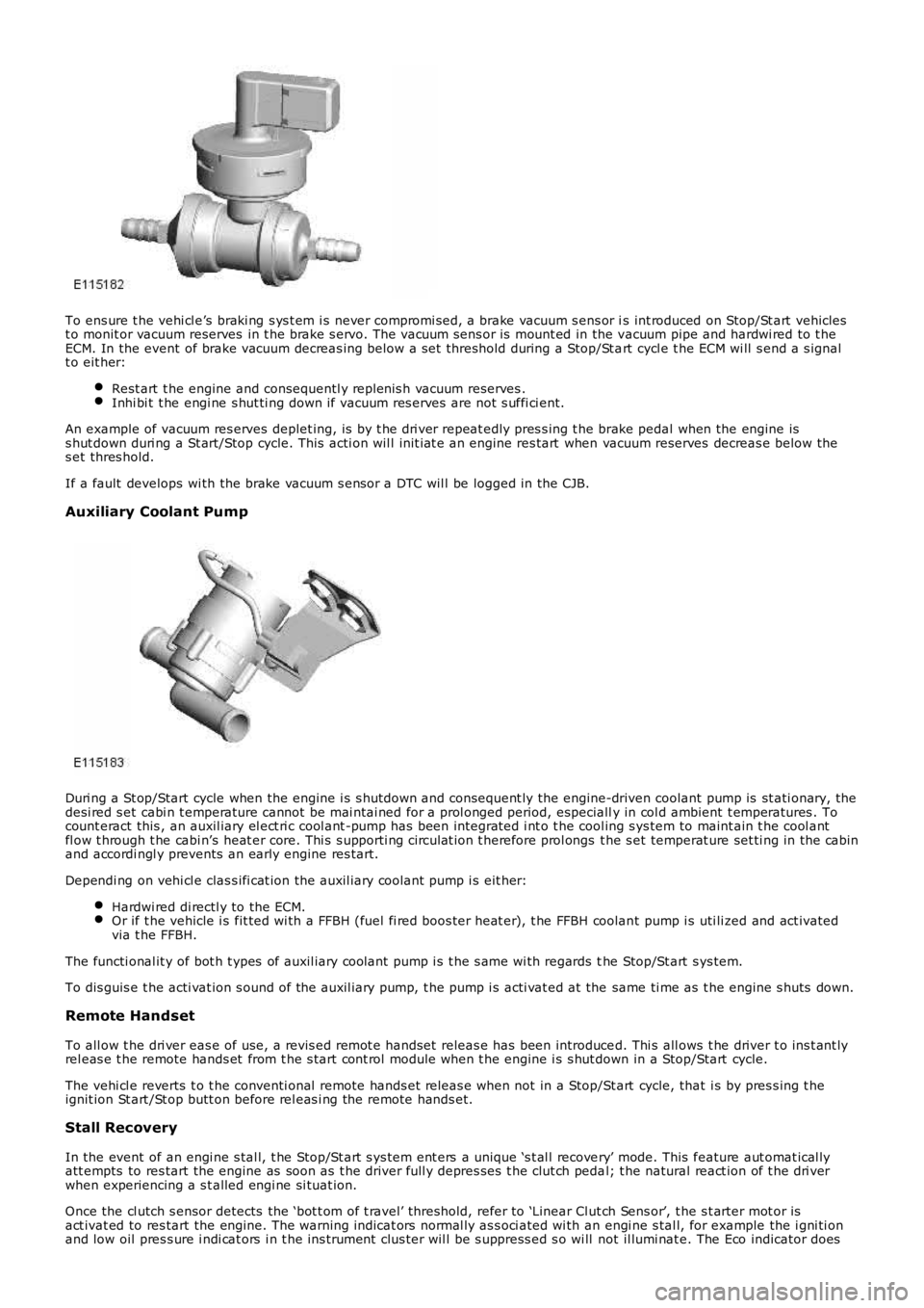
To ens ure t he vehi cl e’s braki ng s ys t em i s never compromi sed, a brake vacuum s ens or is int roduced on Stop/St art vehiclest o monit or vacuum reserves in t he brake s ervo. The vacuum sens or is mount ed in the vacuum pipe and hardwi red to t heECM. In the event of brake vacuum decreas ing below a s et threshold during a Stop/St art cycl e t he ECM wi ll s end a s ignalt o eit her:
Rest art t he engine and consequentl y replenis h vacuum reserves .Inhi bi t t he engi ne s hut ti ng down if vacuum res erves are not s uffi ci ent.
An example of vacuum res erves deplet ing, is by t he dri ver repeat edly pres s ing t he brake pedal when the engine iss hut down duri ng a St art/Stop cycle. This acti on wil l init iat e an engine res tart when vacuum reserves decreas e below thes et thres hold.
If a fault develops wi th the brake vacuum s ensor a DTC wil l be logged in the CJB.
Auxiliary Coolant Pump
Duri ng a St op/Start cycle when the engine i s s hutdown and consequent ly the engine-driven coolant pump is st ati onary, thedesi red s et cabi n t emperature cannot be mai ntai ned for a prol onged period, especially in col d ambient t emperatures . Tocount eract this , an auxil iary el ect ri c cool ant -pump has been integrat ed i nt o t he cool ing s ys tem to maint ain t he cool antfl ow t hrough t he cabi n’s heat er core. Thi s s upporti ng ci rculat ion t herefore prol ongs t he s et temperat ure set ti ng in the cabinand accordi ngl y prevents an early engine res tart.
Dependi ng on vehi cl e clas s ifi cat ion the auxil iary coolant pump i s eit her:
Hardwi red di rectl y to the ECM.Or if t he vehicle i s fit ted wi th a FFBH (fuel fi red boos ter heat er), t he FFBH coolant pump i s uti li zed and act ivatedvia t he FFBH.
The functi onal it y of bot h t ypes of auxil iary coolant pump i s t he s ame wi th regards the Stop/St art s ys tem.
To dis guis e t he acti vat ion s ound of the auxil iary pump, t he pump i s acti vat ed at the same ti me as t he engine s huts down.
Remote Handset
To all ow t he dri ver eas e of use, a revis ed remot e handset releas e has been introduced. Thi s all ows t he driver t o ins t ant lyrel eas e t he remote hands et from t he s tart cont rol module when t he engine i s s hut down in a Stop/Start cycle.
The vehi cl e reverts t o t he conventi onal remote hands et releas e when not in a Stop/Start cycle, that i s by pres s ing t heignit ion St art /St op butt on before rel eas i ng the remote hands et.
Stall Recovery
In the event of an engi ne s tal l, t he Stop/St art s ys tem ent ers a unique ‘s t al l recovery’ mode. This feature aut omat ical lyatt empts to res tart the engine as soon as t he driver full y depres ses t he clut ch pedal; t he natural react ion of t he dri verwhen experiencing a s t alled engi ne si tuat ion.
Once the cl utch s ensor detects the ‘bot t om of t ravel’ threshold, refer to ‘Linear Clut ch Sens or’, t he s t arter mot or isact ivat ed to res tart the engine. The warni ng indicat ors normal ly as s oci ated wi th an engi ne s tal l, for example the i gni ti onand low oil pres s ure i ndi cat ors i n t he ins t rument clus ter wil l be s uppress ed s o wi ll not il lumi nat e. The Eco indicator does
Page 1108 of 3229
however remain i ll uminated.
A ‘st all recovery’ event is the onl y s tat e when t he Stop/St art s yst em wil l permit t he engine t o be s t art ed when thet ransmis s ion i s in gear; hence t he requirement for t he cl utch pedal to be full y depres sed. If the s t all recovery fai ls and t heengi ne does not res tart, t he dri ver wi ll be reques ted vi a t he Mess age Center t o ‘s elect neutral ’ to at t empt anot her rest art .
If the engine does not res t art aft er thi s request t he ‘st all recovery’ mode wil l ti me-out and deact ivate. At t his point t he‘Eco’ i con in t he i ns t rument panel wi ll exti ngui sh and the light s usual ly as s ociat ed wi th an engi ne st all wi ll il lumi nat e. As ares ult t he dri ver will be requi red to perform a convent ional engi ne res tart.
Alt hough st all recovery i s a feat ure of t he St op/Start sys t em i t is pos si ble for it t o acti vat e i ndependent ly from t heStop/St art parameters . For exampl e:
If the St op/Start s ys t em has been deact ivated by the driver st all recovery wi ll s ti ll funct ion.Stal l recovery wil l act ivate at ambi ent temperat ures as l ow as (minus ) - 2°C, whereas the St op/Syst em operat ingt emperature threshold is above 4°C.Different t o t he operat ion of t he Stop/St art s yst em, s tal l recovery wil l st il l functi on when the vehicle is t owing;refer to the ‘Trail er Towi ng’ s ect ion.
• NOTE: As t he neces s ary cri teria will not have been sat is fi ed when t he vehi cl e i s at the beginning of a journey s t allrecovery wi ll not functi on. For exampl e, if t he vehi cl e s tal ls when l eavi ng the garage or driveway a convent ional engineres t art wi ll be required.
Trailer Towing
The Stop/St art s ys tem wil l aut omati cal ly di sabl e when t rail er light s are det ect ed by t he CJB via s ignals from t he t rail ermodule, t hi s informat ion i s t hen trans mi tt ed t o t he ECM. It i s not pos s ibl e for t he s ys t em t o det ect when a trai ler powerplug i s ins ert ed i n the vehicl e’s t owi ng s ocket s o it us es operat ion of t he trail er l ights as it s indi cat or.
The t rail er towing sys tem inhi bi ts St op/St art as i t is pos s ible that trail er power requirements could interfere wit h t heoperati on of the bat tery monit ori ng s ys t em. In parti cul ar, a t rai ler batt ery could revers e t he feed current t o t he vehicleduri ng an engi ne cranking event , t hi s coul d pos si bly:
Confus e t he bat t ery monit ori ng s ys t em i nto det ect ing an unreal is t ically smal l current at engi ne cranking.Rupture the fus e as sociat ed wit h t he t rail er modul e.
Climate Control System
• NOTE: The ‘ECON’ butt on has been renamed ‘A/C’ to prevent confus ion wi th the St op/St art s yst em ‘Eco’ s wit ch.
A number of changes have been made to the l ogi c and operati on of climat e control system, wit hi n a St op/St art cycle to:
maint ain occupant comfortprevent winds hi eld mis ti ngcons erve bat tery power.
This has been achi eved by the ATC (automat ic t emperat ure control) module monit oring and varyi ng, as necess ary variousclimate control funct ions wi thi n a St op/Start cycle.
In s ome circums t ances t he ATC has t he capabil it y to inhibit an engi ne s hut down or init iat e an engine rest art wit hi n aStop/St art cycle. Thi s i s achi eved by t he ATC module communi cat ing wit h t he CJB on the medi um s peed CAN. The variousoverri de functi ons the ATC has in a St op/St art cycl e are di s cus s ed bel ow:
Coolant temperat ure
The ATC module wil l i nhibit an engine shut down or i nit iat e an engine res t art wi thi n a St op/Start cycle if t he coolantt emperature fal ls below the calculat ed t hreshol d to s upport t he cabin t emperat ure s et by t he vehi cl e occupant s .
W i nds hiel d demis t ing
The variant of cli mate control fi tt ed t o the vehicl e influences t he s oft ware changes that have been made. For exampl e, thebase cl imat e-control s ys tem does not have a humi dit y s ens or, as us ed on a highline sys tem t o ini ti at e a winds hi elddemis t . Therefore, a calculat ion for demis ti ng the winds hi eld i s made us ing t he s ignals from t he rai n s ens or and ambientt emperature s ens or. Us i ng the probabi lit y t hat windshi eld mis ti ng wil l occur if i t is raining and t he ambi ent t emperat ure i scool , the ATC wil l presume a wi nds hiel d demis t is required and s tart the engine when i n a St op/St art cycl e.
Evaporat or temperat ure the main cause of windshi eld mis ti ng is al s o monit ored and t he high-line cl imat e cont rol s yst emwil l periodicall y cool t he evaporat or as neces s ary t o reduce mi s ti ng during a Stop/St art cycl e. The sys tem operates thewinds hield demis t s hut ter and i f the evaporator i s wet t he shut ter wi ll remai n clos ed for a few seconds after an engineres t art unti l the vapor is di ss ipat ed.
If the driver sel ect s eit her ‘programmed defros t ’ or t he ‘wi ndshi el d heater’ i t is as s umed t hat a qui ck demis t of thewinds hield is requi red. Therefore, t he ATC vi a the CJB will ei ther: i nhibit an engine shut down or i nit iat e an engine res t art .
Heater fan speed
Duri ng an engine s hutdown t he ATC monit ors cabin temperat ure and maint ai ns the fan speed at a l evel that wi ll cons erve,for as l ong as poss ibl e t he heat i n t he core of t he cabi n heat er. If the driver s elect s a hi gher fan s peed and the heatcannot be mai ntained i n t he heat er core, the engine will rest art .
Heated rear window and heated s eats
If the heated rear window or heated s eats are acti ve or act ivated during an engine shut down event t he power out put oft he relevant s ys t em wi ll be i nt errupted unt il the engi ne is rest art ed. The tell -t ale light i n t he relevant s wit ch wil lil lumi nat e t o i ndi cat e t he s ys t em i s act ive even t hough the s ys tem is recei vi ng no power. This feature is us ed t o conservebatt ery power.
Page 1109 of 3229
Fuel fired heat er
The FFBH (fuel fired boost er heat er) and St op/Start s ys t em wi ll not operate si mult aneous ly, due to low ambientt emperatures bei ng a fact or in t he funct ion of both sys tems .
Hood Latch Ajar-Switch
W ARNING: To avoi d injury when performing repai r work on t he vehicle al ways di s abl e the Stop/St art s ys tem bypres s ing t he ‘ECO’ butt on, ens ure that ‘ECO STOP/START OFF’ is di s pl ayed in t he mes sage Cent er and the ECO tel l-taleli ght in t he s wit ch is ext inguis hed.
The hood lat ch ajar-s wit ch hardwired to the CJB, has two functi ons :
Acts as a s top i nhi bit or, all owing t he engi ne t o remai n running if t he hood latch i s rel eased.Deact ivates the St op/Start s ys t em i f an engi ne s top i s t aki ng place, t his res ul ts in an engine st all ed condit ion. Theengi ne can be res t art ed usi ng t he ignit ion but ton. Stal l recovery wil l not funct ion i n t hi s condi ti on; refer t o t he StallRecovery secti on.
Aft er the hood i s clos ed reacti vat ion of t he Stop/Start sys tem is achieved by manuall y s tarti ng the engine.
System Fault
The Stop/St art s ys tem is aut omati cal ly acti vat ed each ti me an ignit ion cycl e occurs; t he dri ver will be i nformed t he sys t emis operat ing by the t ell -t ale l ight in the Eco s wi tch i lluminati ng. If the tell -t ale light does not il luminat e t hi s wi ll indicat et hat t here i s eit her a s ys t em faul t or the sys tem is not avail abl e. Onl y when t he dri ver at tempt s t o act ivat e t he sys t em bypres s ing t he ‘Eco’ but ton will t hey be informed of a fault by ‘ECO STOP/START FAULT’ being di spl ayed i n t he mes sageCenter.
Owi ng to the St op/Start s ys t em’s complexit y due t o many ot her vehicle modul es and communicat ion net works i nvol ved i nit s funct ion. It i s recommended t hat al l ot her sys tem faul ts be init ial ly diagnos ed and eliminated when inves t igati ngStop/St art fault s as t hes e could affect the operat ion of t he St op/Start sys tem.
Syst em DTC (di agnos ti c troubl e code)can be diagnos ed us ing Land Rover approved di agnos ti c equi pment.
STOP INHIBITORS, START INITIATORS AND START INHIBITORS
A number of s el ect able feat ures or vehicle si tuat ions can infl uence t he operat ion of t he Stop/St art s yst em’s operati on.Thes e can, depending on the parti cular circumst ances :
prevent the engine s hutt ing down (s t op inhibi tor),ini ti at e an aut onomous res tart (s tart ini ti at or),prevent an engi ne res t art (st art i nhi bit or).
Stop Inhibitors
Under normal ci rcums tances the St op/St art s ys t em wi ll automat icall y s hut down t he engi ne if:
t he vehi cl e is st ati onary,t he trans mi s si on is in neutral,t he cl utch pedal i s ful ly releas ed.
The fol lowing condit ions wi ll inhibi t the engine from s hutt ing down:
Dri ver effected st op inhi bi tor
The fol lowing driver effect ed condi ti ons will i nhi bit t he engi ne from shut ti ng down:
Dri ver s wi tches off t he Stop/St art s ys temTrans mis s ion not i n neut ral((no te that the d rive r re sting their ha nd o n the g ea r le ve r ca n move the tra ns mis sion o ut o f the ne utra l w ind o w w itho ut e nga g ing a ge a r))
Clut ch pedal not full y rel easedAccelerator pedal depres s edHood is openDri ver’s door is openDri ver’s safet y belt i s dis engagedHDC (hil l decent cont rol) i s acti veTR (terrain res pons e) mode i s act iveCli mate cont rol s ys t em us ed above cal ibrat ed thresholdW i nds hiel d demis t i s operati ngTrai ler electrical connect ion det ect ed
Vehicle s ys tem effect ed s top i nhi bit or
The fol lowing vehicl e s ys t em condi ti ons wil l inhibit t he engine from s hut ti ng down:
Dri ver s wi tches off t he Stop/St art s ys temBrake s ervo vacuum below thres holdBatt ery cold cranki ng capabil it y below t hres holdBatt ery s t ate of charge i s lowCatal yt ic converter out si de eit her pre or post cali brati on rangeDPF (di esel part iculat e filt er) i s regenerat ingEngi ne cool ant temperat ure bel ow t hreshol dEngi ne oil t emperature below thres hold