2006 LAND ROVER FRELANDER 2 fuel type
[x] Cancel search: fuel typePage 96 of 3229
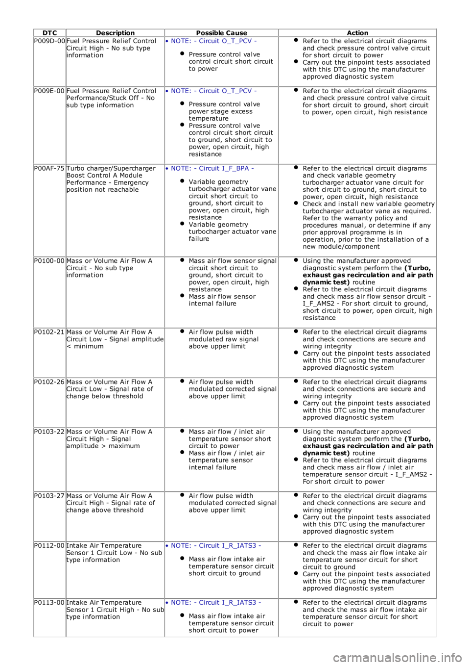
DT CDescriptionPossible CauseAction
P009D-00Fuel Pres s ure Rel ief ControlCircui t High - No s ub typeinformat ion
• NO TE: - Ci rcuit O_T_PCV -
Pres s ure control val vecontrol circui t s hort circuitt o power
Refer to the el ect ri cal circui t diagramsand check pres s ure control valve ci rcuitfor s hort circui t to powerCarry out t he pinpoint t est s as s oci at edwit h t his DTC us ing the manufact urerapproved di agnos ti c s ys t em
P009E-00Fuel Pres s ure Rel ief ControlPerformance/Stuck Off - Nos ub type i nformati on
• NO TE: - Ci rcuit O_T_PCV -
Pres s ure control val vepower s tage exces st emperaturePres s ure control val vecontrol circui t s hort circuitt o ground, s hort ci rcuit t opower, open circui t, highresi st ance
Refer to the el ect ri cal circui t diagramsand check pres s ure control valve ci rcuitfor s hort circui t to ground, s hort circui tto power, open ci rcuit , hi gh res i st ance
P00AF-75Turbo charger/SuperchargerBoost Cont rol A ModulePerformance - Emergencyposi ti on not reachable
• NO TE: - Ci rcuit I_F_BPA -
Vari able geometryt urbocharger actuat or vanecircui t s hort ci rcuit t oground, s hort circuit t opower, open circui t, highresi st anceVari able geometryt urbocharger actuat or vanefailure
Refer to the el ect ri cal circui t diagramsand check variabl e geomet ryturbocharger act uator vane ci rcuit forshort ci rcuit t o ground, s hort circuit t opower, open ci rcuit , high res i st anceCheck and i ns t all new vari abl e geometryturbocharger act uator vane as required.Refer to the warrant y policy andprocedures manual , or det ermi ne if anyprior approval programme is i noperati on, prior to the i nst all ati on of anew module/component
P0100-00Mas s or Vol ume Ai r Fl ow ACircui t - No s ub t ypeinformat ion
Mas s air flow sens or si gnalcircui t s hort ci rcuit t oground, s hort circuit t opower, open circui t, highresi st anceMas s air flow sens ori nt ernal fai lure
Usi ng t he manufacturer approveddiagnos t ic s yst em perform t he (T urbo,exhaust gas recirculation and air pathdynamic test) rout ineRefer to the el ect ri cal circui t diagramsand check mas s air flow sens or ci rcuit -I_F_AMS2 - For short ci rcuit t o ground,short ci rcuit t o power, open circui t, highres is t ance
P0102-21Mas s or Vol ume Ai r Fl ow ACircui t Low - Signal amplit ude< minimum
Ai r flow puls e wi dt hmodulat ed raw s ignalabove upper l imi t
Refer to the el ect ri cal circui t diagramsand check connecti ons are s ecure andwiring i ntegri tyCarry out t he pinpoint t est s as s oci at edwit h t his DTC us ing the manufact urerapproved di agnos ti c s ys t em
P0102-26Mas s or Vol ume Ai r Fl ow ACircui t Low - Signal rat e ofchange below threshold
Ai r flow puls e wi dt hmodulat ed correct ed si gnalabove upper l imi t
Refer to the el ect ri cal circui t diagramsand check connecti ons are s ecure andwiring i ntegri tyCarry out t he pinpoint t est s as s oci at edwit h t his DTC us ing the manufact urerapproved di agnos ti c s ys t em
P0103-22Mas s or Vol ume Ai r Fl ow ACircui t High - Si gnalampli tude > maximum
Mas s air flow / inlet ai rt emperature s ensor s hortcircui t to powerMas s air flow / inlet ai rt emperature s ensori nt ernal fai lure
Usi ng t he manufacturer approveddiagnos t ic s yst em perform t he (T urbo,exhaust gas recirculation and air pathdynamic test) rout ineRefer to the el ect ri cal circui t diagramsand check mas s air flow / inlet ai rtemperat ure sens or ci rcuit - I_F_AMS2 -For s hort circui t to power
P0103-27Mas s or Vol ume Ai r Fl ow ACircui t High - Si gnal rat e ofchange above threshold
Ai r flow puls e wi dt hmodulat ed correct ed si gnalabove upper l imi t
Refer to the el ect ri cal circui t diagramsand check connecti ons are s ecure andwiring i ntegri tyCarry out t he pinpoint t est s as s oci at edwit h t his DTC us ing the manufact urerapproved di agnos ti c s ys t em
P0112-00Int ake Air Temperat ureSens or 1 Ci rcuit Low - No s ubt ype i nformati on
• NO TE: - Ci rcuit I_R_IATS3 -
Mas s air flow int ake ai rt emperature s ensor circui ts hort circui t to ground
Refer to the el ect ri cal circui t diagramsand check t he mas s air flow i ntake airtemperat ure sens or ci rcuit for shortci rcuit t o groundCarry out t he pinpoint t est s as s oci at edwit h t his DTC us ing the manufact urerapproved di agnos ti c s ys t em
P0113-00Int ake Air Temperat ureSens or 1 Ci rcuit Hi gh - No s ubt ype i nformati on
• NO TE: - Ci rcuit I_R_IATS3 -
Mas s air flow int ake ai rt emperature s ensor circui ts hort circui t to power
Refer to the el ect ri cal circui t diagramsand check t he mas s air flow i ntake airtemperat ure sens or ci rcuit for shortci rcuit t o power
Page 754 of 3229
Publi s hed: 11-May-2011
Engine - TD4 2.2L Diesel - Engine
Des cript ion and Operat ion
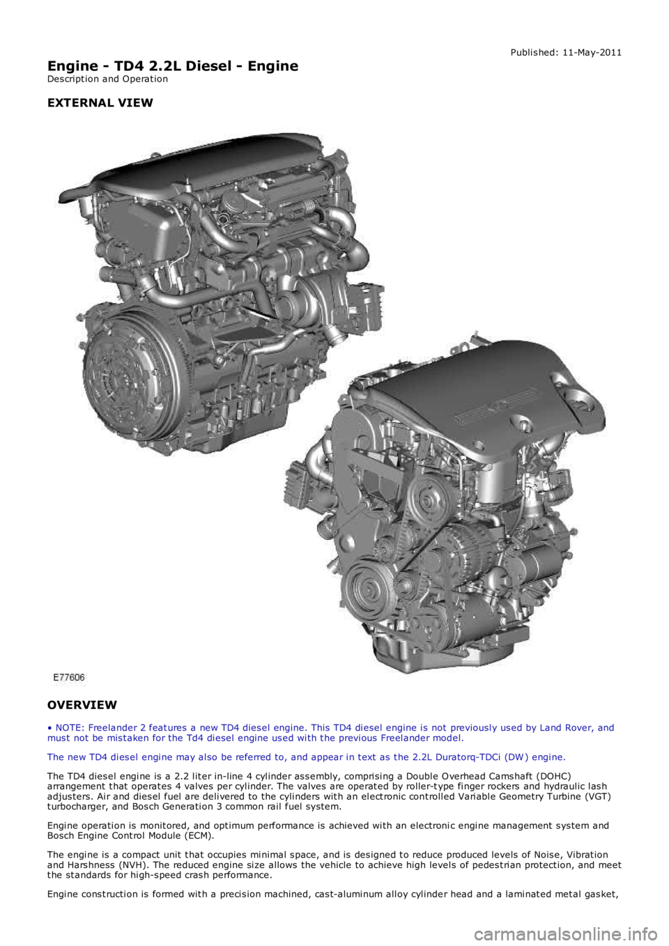
EXTERNAL VIEW
OVERVIEW
• NOTE: Freelander 2 feat ures a new TD4 dies el engine. This TD4 di esel engine i s not previousl y us ed by Land Rover, andmus t not be mis t aken for the Td4 di esel engine us ed wi th t he previ ous Freel ander model.
The new TD4 di es el engi ne may al so be referred to, and appear i n t ext as t he 2.2L Duratorq-TDCi (DW ) engi ne.
The TD4 dies el engi ne is a 2.2 l it er in-line 4 cyl inder as s embly, compri si ng a Double O verhead Cams haft (DOHC)arrangement t hat operat es 4 valves per cyl inder. The valves are operat ed by roller-type fi nger rockers and hydraul ic l as hadjus ters. Ai r and dies el fuel are deli vered to the cyli nders wit h an el ect ronic cont roll ed Vari abl e Geometry Turbine (VGT)t urbocharger, and Bos ch Generati on 3 common rail fuel s ys tem.
Engi ne operati on is monit ored, and opt imum performance is achieved wi th an electronic engi ne management s ys tem andBosch Engine Cont rol Module (ECM).
The engi ne is a compact unit t hat occupies mi nimal s pace, and is des igned t o reduce produced levels of Nois e, Vibrat ionand Hars hness (NVH). The reduced engine si ze allows the vehicle to achieve high level s of pedes t ri an protect ion, and meett he st andards for hi gh-s peed cras h performance.
Engi ne cons t ructi on is formed wit h a preci s ion machined, cas t-alumi num all oy cyl inder head and a lami nat ed met al gas ket,
Page 784 of 3229
The cyl inder head and st ructural cams haft cover are manufactured to form mat ing parts . The part s are mil led i n a si ngl eoperati on and accurat ely pos it ioned wi th 2 alignment s leeves. The 2 components mus t al ways be ins tall ed t oget her, andnot renewed as s eparate component s . The cyl inder head and cams haft cover are s eal ed to each ot her during manufact urewit h a gas ket and s ili cone bas ed s eal ant, and are s ecured wit h 27 bolt s . An oil s eal i nst all ed at the front of t he cyl inderhead provides s eal ing of t he exhaus t camshaft hous ing. The open port s at the rear of the cyli nder head are sealed wit ht he vacuum pump and hi gh-pres s ure fuel pump s eal ing rings .
Two ali gnment sl eeves correct ly l ocat e t he cyl inder head and gas ket to t he cylinder block. The cyli nder head is secured t ot he cyl inder bl ock wit h 10 deep-s eat ed bolt s .
• NOTE: The cyl inder head bol ts are not acces si ble wit h the st ruct ural cams haft cover i nst all ed.
• NOTE: The cyl inder head is not t o be reworked.
The cyl inder head is manufact ured from al uminum alloy, havi ng valve s eats and guides made of s i nt ered st eel. Thecyl inder head is precis ely machi ned and mil led t o i ncorporate t he 4 combus ti on chambers, cams haft l ower beari nghous i ngs , oil drill ings and cool ant gal leri es, and t he air i ntake, val ve ti ming and fuel sys t em component bores andhous i ngs .
The desi gn of the cyli nder head maximizes air flow and s wi rl i n the combus ti on chambers. The 2 int ake val ve seat s aremachined wit h rais ed profil es that act to promote swi rl of t he int ake ai r fl ow. Combined wit h t he acti on of the i ntakemanifold heli cal port , t he s wirl effect of the 2 int ake port profi les al lows t he air and i nject ed fuel t o complet el y mi x, andreach t he outer edge of the combus ti on chamber.
The s truct ural camshaft cover is manufact ured from alumi num all oy, and i s machined on t he upper s urface wit h t hecamshaft upper bearing hous ings . The cover is al so formed wi th 4 int ake ai r fi ll ing t racts , fuel i nject or bores and ori fi cesfor t he cyl inder head cover PCV components . The i nt ake air t racts join the i ntake air mani fold to the cyli nder head int akefi ll ing port s .
The cyl inder head al s o provides t he mounti ng locati ons for the foll owing:
Front engi ne mounti ngFront and rear engine l ifti ng eyesInt ake and exhaus t manifol dsEGR valve and coolerFuel fil ter s upport bracketThermal cont rol moduleVacuum pump and high-press ure fuel pump.
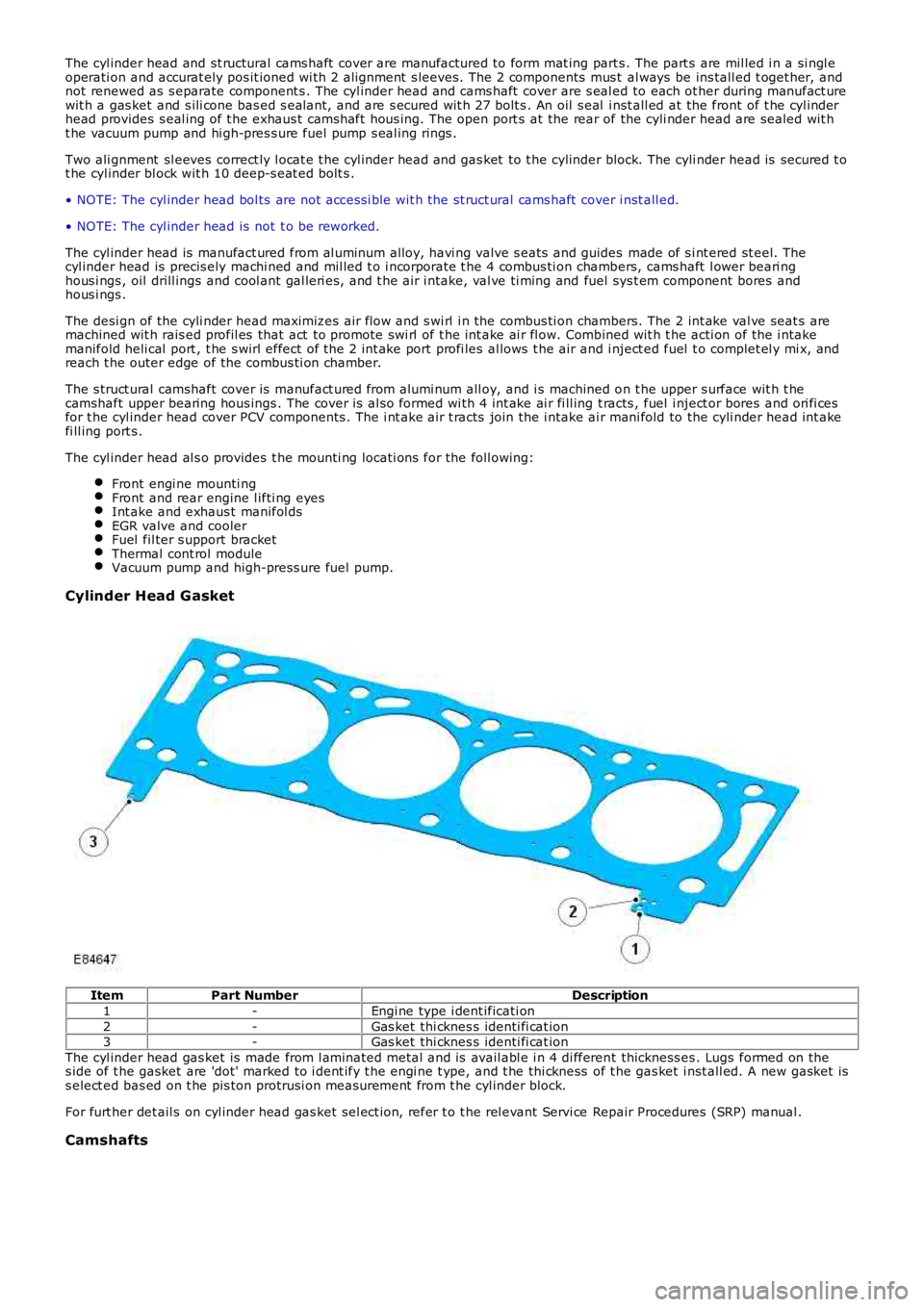
Cylinder Head G asket
ItemPart NumberDescription
1-Engi ne type i dent ificati on
2-Gas ket thi cknes s identi fi cat ion3-Gas ket thi cknes s identi fi cat ion
The cyl inder head gas ket is made from l aminated metal and is avail abl e i n 4 di fferent thickness es . Lugs formed on thes ide of t he gasket are 'dot' marked to i dent ify t he engi ne t ype, and t he thi ckness of t he gas ket i nst all ed. A new gasket iss elect ed bas ed on t he pis ton protrusi on meas urement from t he cyl inder block.
For furt her det ail s on cyl inder head gas ket sel ect ion, refer t o t he rel evant Servi ce Repair Procedures (SRP) manual .
Camshafts
Page 792 of 3229
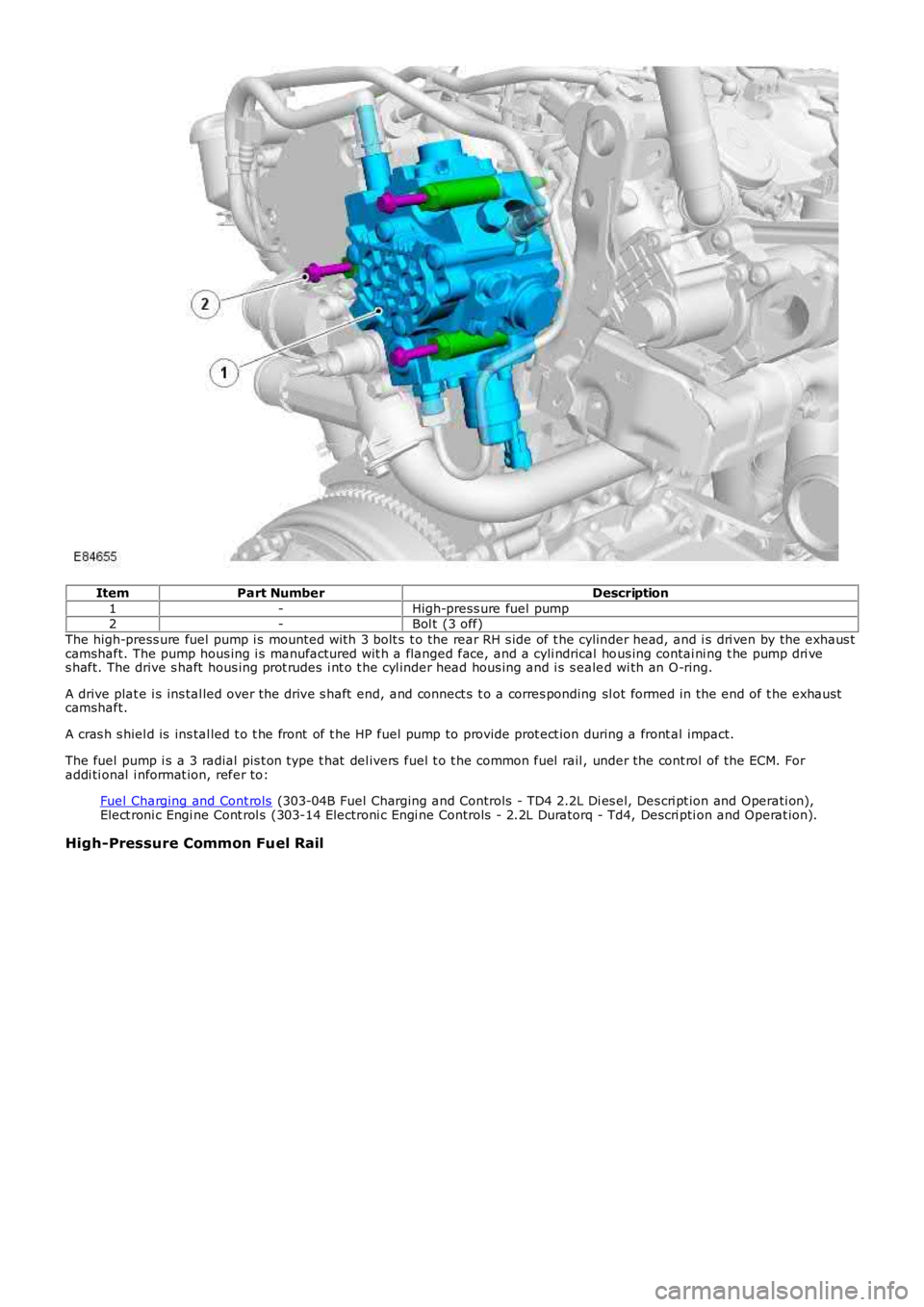
ItemPart NumberDescription
1-High-press ure fuel pump2-Bol t (3 off)
The high-press ure fuel pump i s mounted wi th 3 bolt s t o the rear RH s ide of t he cylinder head, and i s dri ven by the exhaus tcamshaft. The pump hous ing i s manufactured wit h a flanged face, and a cyli ndrical hous ing contai ni ng t he pump dri ves haft. The drive s haft hous ing prot rudes i nt o t he cyl inder head hous ing and i s s ealed wi th an O-ring.
A drive plat e i s ins tal led over the drive s haft end, and connect s t o a corres ponding sl ot formed in the end of t he exhaus tcamshaft.
A cras h s hiel d is ins tal led t o t he front of t he HP fuel pump to provide prot ect ion during a front al impact.
The fuel pump i s a 3 radial pis t on type t hat del ivers fuel t o t he common fuel rail , under the cont rol of the ECM. Foraddi ti onal i nformat ion, refer to:
Fuel Charging and Cont rols (303-04B Fuel Charging and Controls - TD4 2.2L Di es el, Des cri pt ion and Operati on),Elect roni c Engi ne Cont rol s (303-14 Electroni c Engi ne Controls - 2.2L Duratorq - Td4, Descri pti on and Operat ion).
High-Pressure Common Fuel Rail
Page 799 of 3229
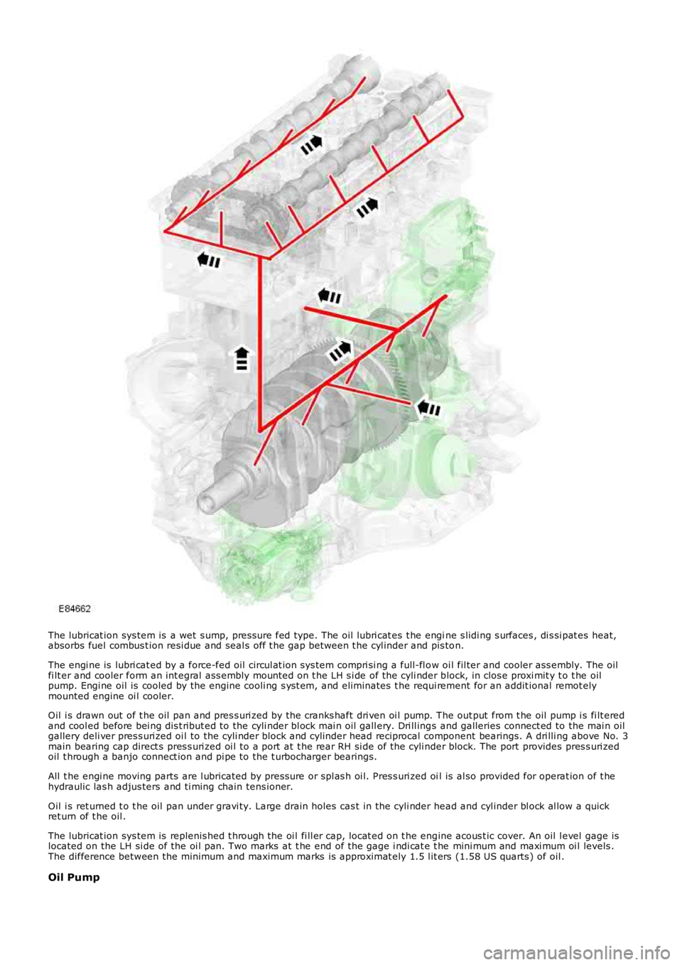
The lubricat ion sys tem is a wet s ump, pres sure fed type. The oil lubri cat es t he engine s lidi ng s urfaces , di s si pat es heat,absorbs fuel combus t ion resi due and seal s off t he gap between t he cyl inder and pis ton.
The engi ne is lubri cat ed by a force-fed oil circul at ion sys tem compri si ng a full-fl ow oi l fil ter and cooler ass embly. The oilfi lt er and cooler form an int egral ass embly mount ed on t he LH s i de of the cyli nder block, in clos e proxi mit y t o t he oilpump. Engi ne oil is cooled by the engine cooli ng s ys t em, and eliminates t he requi rement for an addit ional remot elymounted engine oi l cooler.
Oil i s drawn out of t he oil pan and pres s uri zed by the cranks haft dri ven oi l pump. The out put from t he oil pump i s fi lt eredand cool ed before bei ng dis t ribut ed to the cyli nder bl ock mai n oil gall ery. Dri ll ings and galleries connect ed to the mai n oilgallery deli ver pres s uri zed oi l to the cyli nder block and cyl inder head reciprocal component bearings. A dri lli ng above No. 3main bearing cap direct s pres s uri zed oi l to a port at t he rear RH si de of the cyli nder block. The port provides pres s uri zedoil t hrough a banjo connect ion and pi pe to the t urbocharger bearings.
All t he engi ne moving parts are l ubricated by press ure or spl as h oi l. Pres s uri zed oil is al so provided for operat ion of t hehydraulic las h adjus ters and ti ming chain tens ioner.
Oil i s ret urned t o t he oil pan under gravi ty. Large drain holes cas t in the cyli nder head and cyl inder bl ock al low a quickret urn of t he oil .
The lubricat ion sys tem is replenis hed t hrough the oi l fi ll er cap, locat ed on t he engine acous t ic cover. An oil l evel gage islocated on the LH si de of the oi l pan. Two marks at t he end of the gage i ndi cat e t he mini mum and maxi mum oi l levels .The difference between the minimum and maximum marks is approximat ely 1.5 l it ers (1.58 US quarts ) of oil .
Oil Pump
Page 996 of 3229
Dies el, Des cript ion and Operat ion).
Fuel i njecti on pres sure is generat ed i ndependent ly of engine s peed and fuel inject ion events . The HP fuel s ys tem iscont rol lable t o t he opti mum level for smoot h operat ion, and is capabl e of devel opi ng an i nject ion press ure up t o 1,600 bar(23,206 psi ). The fuel i njecti on ti ming and vol ume are cal cul at ed by t he ECM t hat als o energizes t he appropriat e piezo-act uated i njector.
The fuel s yst em features a pre-inject ion (pilot ) phas e t o reduce combus ti on noi s e and mechani cal load. On vehiclesins t al led wi th a Di es el Part iculate Fi lt er (DPF), t he fuel s ys tem als o provides a pos t -i nject ion phas e t hat is requi red forregenerat ing t he DPF.For addit ional informat ion, refer t o: Exhaus t Sys t em (309-00B Exhaus t Syst em - TD4 2.2L Di es el, Des cri pt ion andOperat ion).
This t ype of fuel sys t em all ows t he TD4 engi ne t o achi eve excellent l evels of performance and engine res pons e, whilebeing able to meet current and fut ure exhaus t emi s si on legis l at ion.
Fuel charging is achieved wit h a LP and HP fuel s ys t em. The LP fuel s yst em compris es:
Saddl e t ype fuel tankTank mount ed fuel deli very module and integral t rans fer pumpFuel s upply and return li nesFil ter and water s eparator as s embly.For addit ional informat ion, refer t o: Fuel Tank and Lines (310-01B Fuel Tank and Lines - TD4 2.2L Dies el ,Des cript ion and Operat ion).
The HP fuel s ys tem compris es :
HP fuel pump wit h int egral mounted l ift pump and Volume Cont rol Valve (VCV)Common fuel rail wi th integral PCV and press ure s ens or4 pi ezo-injectorsHP connect ing pipesFuel l eak-off pipes .
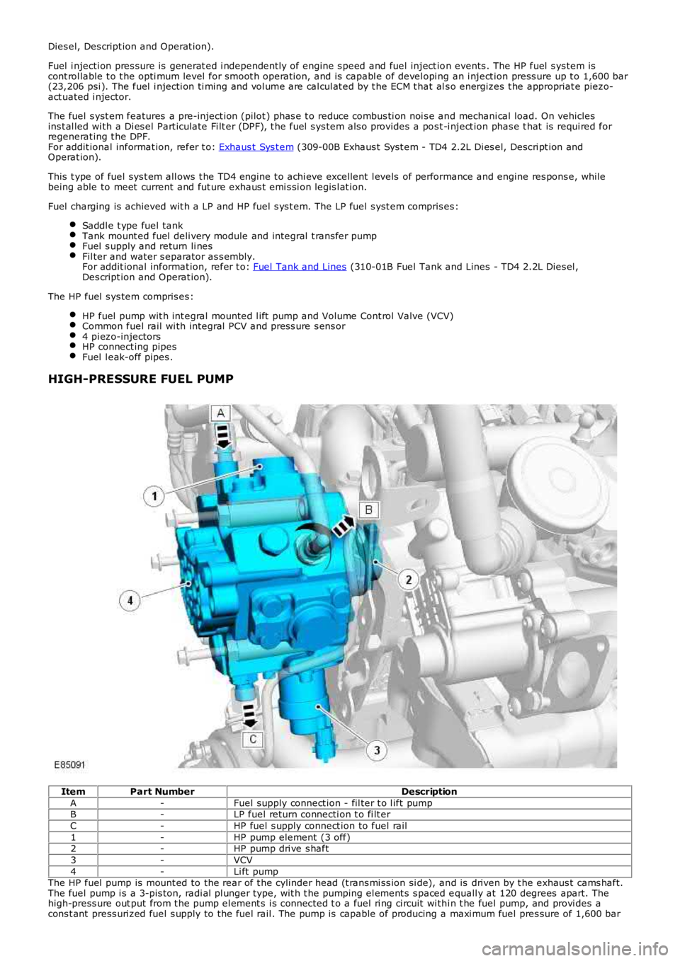
HIGH-PRESSURE FUEL PUMP
ItemPart NumberDescription
A-Fuel supply connect ion - fil ter t o l ift pumpB-LP fuel return connecti on t o fi lt er
C-HP fuel s upply connect ion to fuel rail
1-HP pump element (3 off)2-HP pump dri ve s haft
3-VCV
4-Li ft pumpThe HP fuel pump is mount ed to the rear of t he cylinder head (t rans mi ss ion si de), and is driven by t he exhaus t cams haft.The fuel pump i s a 3-pis ton, radi al pl unger type, wit h t he pumping el ement s s paced equall y at 120 degrees apart. Thehigh-press ure out put from t he pump el ement s i s connected t o a fuel ri ng ci rcuit wi thi n t he fuel pump, and provi des acons t ant press uri zed fuel s upply to the fuel rail . The pump is capable of producing a maxi mum fuel pres sure of 1,600 bar
Page 997 of 3229
(23,206 psi ).
The fuel s yst em HP pump compri ses t he fol lowi ng components :
3 HP pumpi ng element sInt egral li ft pumpVolume Cont rol Valve (VCV).
The HP pump and integral l ift pump mus t not be s eparat ed. The HP pump i s not ti med to t he engi ne.
A controlled amount of fuel i s all owed to leak-off t hrough t he HP pump, and ret urned t hrough a l eak-off pipe t o t he fuelfi lt er. The l eak-off fuel provides cooling and lubri cat ion for the HP pump int ernal components .
Lift Pump
A fuel l ift pump i s mounted t o t he rear of t he fuel pump, and forms an int egral ass embly wit h t he HP pump. The fuel li ftpump i s a gear type pump and connect ed to the fuel fi lt er s upply l ine. The li ft pump creat es a vacuum (negati ve pres s ure)in the s upply l ine t o t he fuel t ank, and draws the fuel from t he tank. The fuel passes t hrough the fuel fi lt er and i s t hendelivered at lift pump pres s ure to the HP pump inl et port.
The li ft pump normal operati ng, negati ve pres sure values are shown for the foll owing engine condi ti ons:
Engine ConditionLift Pump Negative PressureCranking-133 ± 7 mbar (-10 ± 0.5 cmHg)
Full load-267 ± 133 mbar (-20 ± 10 cmHg)
Volume Control Valve (VCV)
The VCV i s mounted on the HP pump, and l ocat ed in the feed port between t he HP pump elements and the fuel l ift pump.The VCV i s a vari abl e pos it ion s olenoid-operat ed valve t hat i s cont rol led by t he ECM wit h a 12V Puls e W idt h Modulat ed(PW M) s ignal. The VCV controls t he quant it y of fuel deli vered by the lift pump t o t he HP pump el ements .
W hen t he HP fuel pump rot ates , pres sure is created when t he VCV i s open and the fuel rail mount ed PCV is cl osed. TheVCV and PCV are vari abl e posi ti on valves, and us ed by t he ECM t o cont rol fuel deli very and fuel s ys tem pres sure.
Duri ng the fuel heat ing period when t he s uppl y fuel t emperature is les s than 40°C (104°F), t he ECM will fully open theVCV. Fuel volume and press ure is t hen cont rol led di rectl y by the PCV under t he cont rol of the ECM.
The VCV i s normal ly open when t he s ol enoi d i s not energi zed by the ECM. The resi s tance val ue of the VCV s ol enoi d coil is2.8 ohms at 20°C (68°F).For addit ional informat ion, refer t o: Electroni c Engi ne Controls - 2.2L Dies el (303-14 El ect ronic Engine Cont rols - 2.2LDies el, Des cript ion and Operat ion).
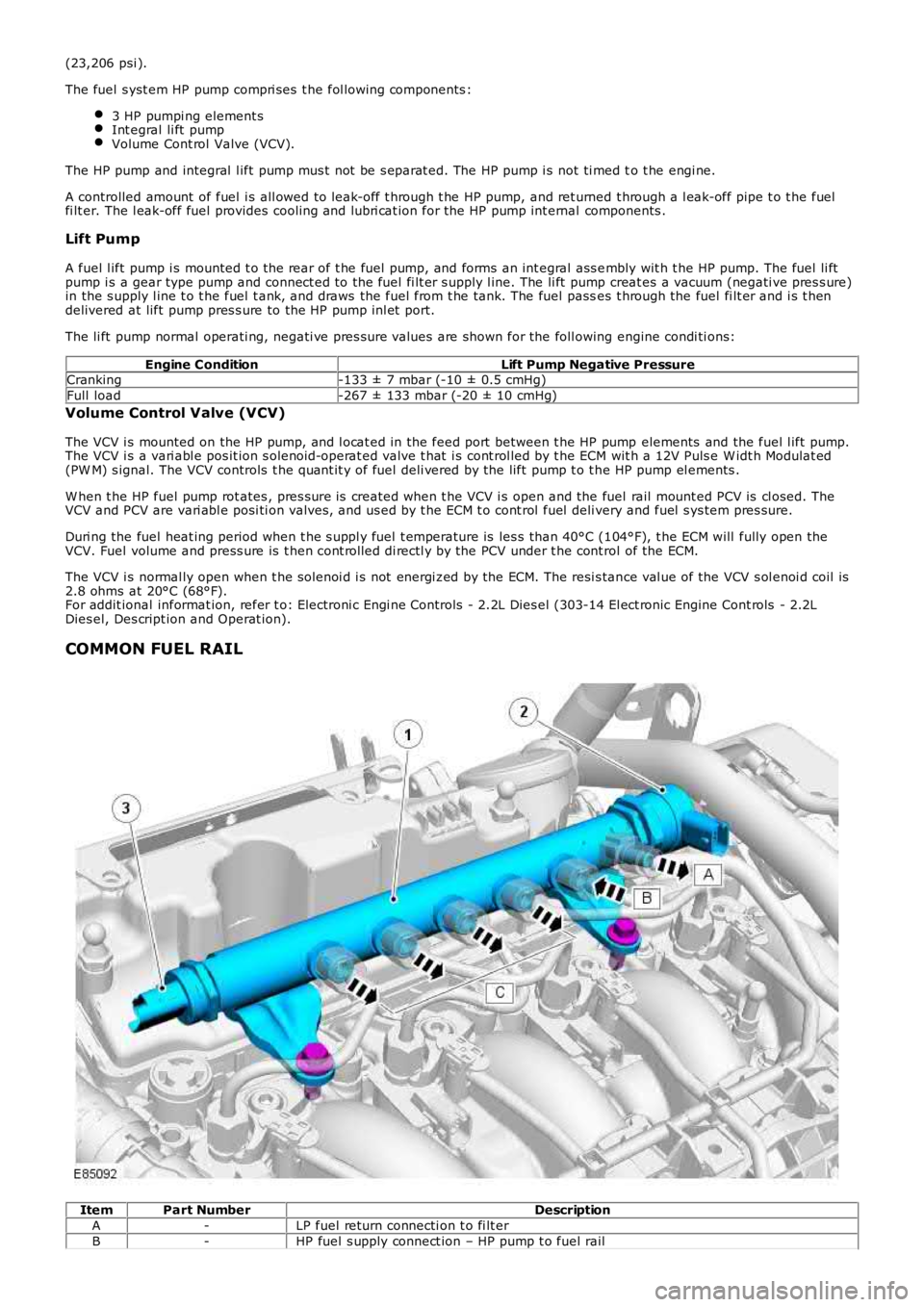
COMMON FUEL RAIL
ItemPart NumberDescription
A-LP fuel return connecti on t o fi lt er
B-HP fuel s upply connect ion – HP pump t o fuel rail
Page 998 of 3229
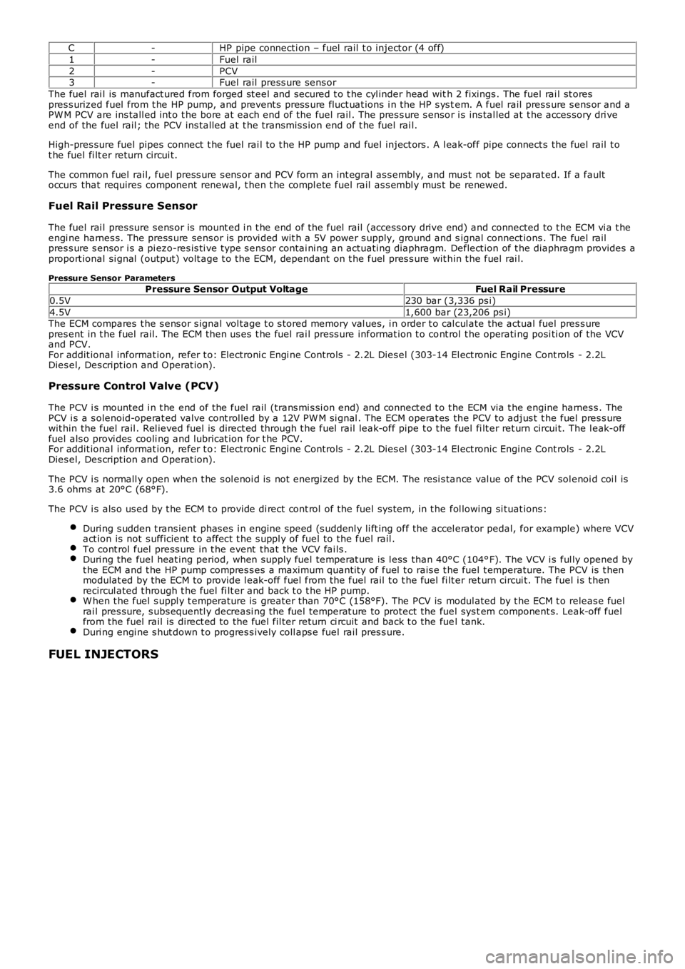
C-HP pipe connecti on – fuel rail t o inject or (4 off)
1-Fuel rail
2-PCV3-Fuel rail press ure sens or
The fuel rai l is manufact ured from forged st eel and secured t o t he cyl inder head with 2 fixings . The fuel rai l st orespres s urized fuel from t he HP pump, and prevent s pres s ure fluct uat ions i n the HP s ys tem. A fuel rail pres s ure s ens or and aPW M PCV are ins tall ed int o t he bore at each end of the fuel rail . The pres s ure s ensor i s ins tal led at t he acces sory dri veend of the fuel rail ; the PCV ins tal led at t he transmis s ion end of t he fuel rai l.
High-pres sure fuel pipes connect t he fuel rai l t o t he HP pump and fuel inject ors . A l eak-off pipe connect s the fuel rail t ot he fuel fi lt er return circui t.
The common fuel rail, fuel press ure s ens or and PCV form an int egral as s embly, and mus t not be separat ed. If a faultoccurs that requires component renewal, t hen t he compl ete fuel rail as s embl y mus t be renewed.
Fuel Rail Pressure Sensor
The fuel rai l pres sure s ens or is mount ed i n t he end of the fuel rail (access ory drive end) and connected to t he ECM vi a t heengi ne harnes s. The press ure sens or is provi ded wit h a 5V power s upply, ground and signal connect ions . The fuel railpres s ure s ensor i s a pi ezo-res is ti ve type s ens or contai ni ng an actuati ng diaphragm. Deflect ion of t he diaphragm provides aproport ional si gnal (output) volt age t o t he ECM, dependant on t he fuel pres s ure wit hin t he fuel rai l.
Pressure Sensor ParametersPressure Sensor Output VoltageFuel Rail Pressure
0.5V230 bar (3,336 ps i)
4.5V1,600 bar (23,206 ps i)The ECM compares t he s ens or s ignal vol tage t o s tored memory val ues, i n order t o cal cul ate the actual fuel pres s urepres ent in t he fuel rail. The ECM then us es t he fuel rai l press ure informat ion t o cont rol t he operati ng posi ti on of the VCVand PCV.For addit ional informat ion, refer t o: Electroni c Engi ne Controls - 2.2L Dies el (303-14 El ect ronic Engine Cont rols - 2.2LDies el, Des cript ion and Operat ion).
Pressure Control Valve (PCV)
The PCV i s mounted i n t he end of the fuel rail (trans mi s si on end) and connect ed t o the ECM via t he engine harnes s . ThePCV i s a s olenoid-operat ed valve cont rol led by a 12V PW M si gnal . The ECM operat es the PCV to adjus t t he fuel pres s urewit hin the fuel rail . Rel ieved fuel is direct ed through t he fuel rail leak-off pipe t o t he fuel fi lt er ret urn circui t. The l eak-offfuel als o provi des cooli ng and lubricat ion for t he PCV.For addit ional informat ion, refer t o: Electroni c Engi ne Controls - 2.2L Dies el (303-14 El ect ronic Engine Cont rols - 2.2LDies el, Des cript ion and Operat ion).
The PCV i s normall y open when t he s ol enoi d is not energi zed by the ECM. The resi s tance val ue of the PCV sol enoi d coi l is3.6 ohms at 20°C (68°F).
The PCV i s als o us ed by t he ECM t o provide di rect cont rol of the fuel sys tem, in t he fol lowi ng si tuat ions :
Duri ng s udden t rans ient phas es i n engine s peed (s uddenl y li ft ing off the accel erat or pedal, for example) where VCVact ion is not s ufficient to affect t he s uppl y of fuel to the fuel rail .To cont rol fuel press ure in t he event that the VCV fai ls .Duri ng the fuel heat ing period, when supply fuel temperat ure is l ess than 40°C (104°F). The VCV i s ful ly opened byt he ECM and t he HP pump compres s es a maximum quanti ty of fuel t o rais e t he fuel t emperature. The PCV is t henmodulat ed by the ECM to provide l eak-off fuel from the fuel rail t o t he fuel fi lt er ret urn circui t. The fuel i s t henrecircul ated t hrough t he fuel fi lt er and back t o t he HP pump.W hen t he fuel s uppl y t emperature is greater t han 70°C (158°F). The PCV is modul ated by t he ECM t o releas e fuelrai l pres sure, s ubs equentl y decreasi ng the fuel temperat ure to protect the fuel sys tem component s. Leak-off fuelfrom the fuel rail is direct ed to the fuel fil ter return ci rcuit and back t o the fuel tank.Duri ng engi ne s hut down t o progres s ively coll aps e fuel rail pres s ure.
FUEL INJECTORS