2006 LAND ROVER FRELANDER 2 fuel type
[x] Cancel search: fuel typePage 999 of 3229
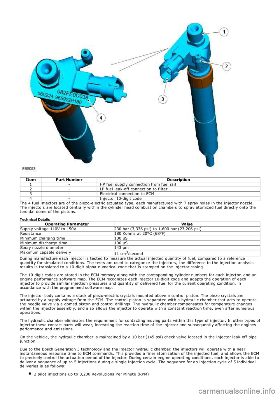
ItemPart NumberDescription
1-HP fuel s uppl y connecti on from fuel rail2-LP fuel leak-off connect ion to fil ter
3-Electrical connect ion t o ECM
4-Inject or 10-digit codeThe 4 fuel i njectors are of t he piezo-el ect ri c act uat ed t ype, each manufactured wit h 7 s pray hol es in the i njector nozzl e.The inject ors are located centrall y wit hin the cyli nder head combus t ion chambers t o s pray at omized fuel direct ly ont o t het oroidal dome of the pi s tons .
Technical Details
O perating ParameterValue
Suppl y volt age 110V to 150V230 bar (3,336 ps i) t o 1,600 bar (23,206 psi )Res is tance180 Kohms at 20°C (68°F)
Mi ni mum chargi ng t ime100 µS
Mi ni mum dis charge ti me100 µSSpray nozzle di amet er143 µm
Maximum capable del ivery11 cm3/s econd
Duri ng manufacture each injector i s tes t ed to measure t he act ual i njected quanti ty of fuel, compared t o a referencequant it y for s i mulat ed condit ions . The tes ts are us ed t o categori ze the i njectors, the difference i n t he inject ion analys isres ult s i s transl ated t o a 10-digit al pha-numerical code t hat is s t amped on t he inject or cas ing.
The 10-digi t codes are s tored in t he ECM memory al ong wit h t he corres pondi ng cyl inder numbers for each inject or, and anengi ne performance s oft ware map. The ECM recogni zes each inject or 10-digit code and adapts t he operat ion of eachinject or to provi de s imi lar i nject ion press ures and quant it y of del ivered fuel for the current operati ng condit ion, inaccordance wit h t he programmed s oft ware map.
The inject or body contai ns a s tack of piezo-electric crys t als mount ed above a cont rol pis ton. The piezo crys t al s areact uated by a s uppl y vol tage from t he ECM. The control pis ton i s s eparated wit h a hydrauli c chamber t hat acts to operat et he needle val ve via a domed pis ton and control dril li ngs . The hydrauli c chamber compens ates for temperat ure changeswit hin the i njector as sembl y, and al so allows the i njector t o operate wit h a cons tant reacti on ti me, even aft er numerousoperati ons .
The hydraulic chamber eliminates t he requi rement for contacti ng moving part s wi thi n t hi s t ype of i njector. In ot her types ofinject or thes e cont act parts will wear, increasi ng t he reacti on ti me of t he inject or and subs equentl y affect ing the enginesperformance and emis s ions .
On t he vehicle, the hydraul ic chamber i s mai nt ained by a 10 bar (145 ps i) check valve locat ed in the injector l eak-off pipejuncti on.
Due t o t he Bosch Generat ion 3 technol ogy and the i njector hydraulic chamber, t he inject ors will operat e wi th a nearins t ant aneous respons e ti me t o ECM commands . This provi des a fi ner at omizat ion of t he inject ed fuel, and al lows t he ECMt o precis ely control the actuat ion peri od of the injector. During certain engi ne operati ng condit ions , each injector i s able t odeliver a s equence of up t o 5 injecti ons during a s ingle i njecti on cycle. The s equence for an injecti on cycle of 5 indivi dualdeliveries is as fol lows :
2 pi lot inject ions up t o 3,200 Revolut ions Per Minute (RPM)
Page 1024 of 3229
Publi s hed: 11-May-2011
Fuel Charging and Controls - Turbocharger - TD4 2.2L Diesel -
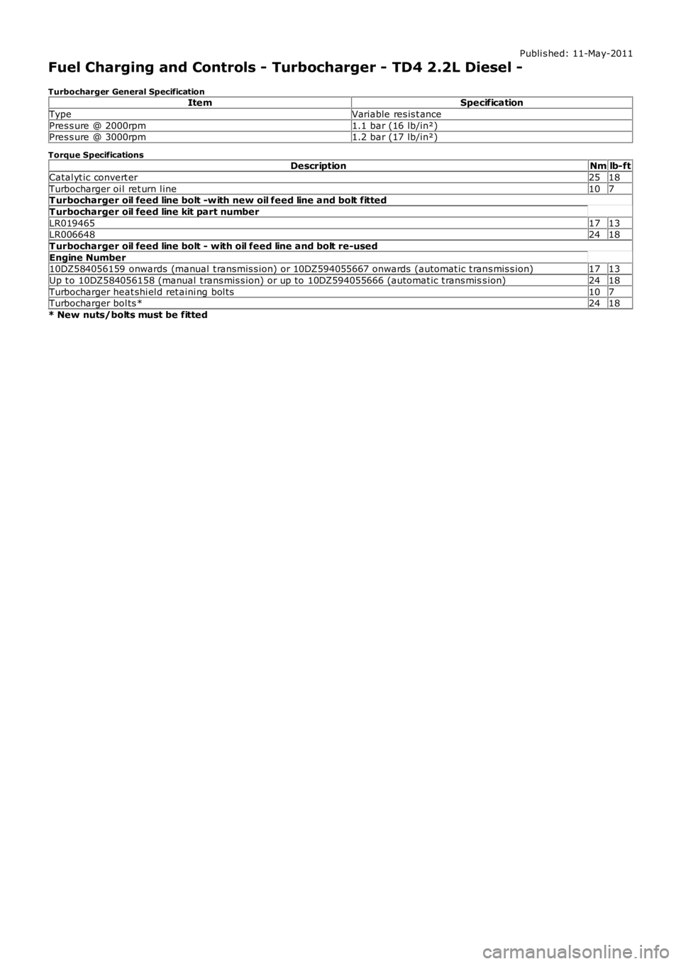
Turbocharger General SpecificationItemSpecification
TypeVariable res is t ance
Pres s ure @ 2000rpm1.1 bar (16 lb/in²)Pres s ure @ 3000rpm1.2 bar (17 lb/in²)
Torque SpecificationsDescriptionNmlb-ft
Catal yt ic convert er2518
Turbocharger oi l ret urn l ine107T urbocharger oil feed line bolt -w ith new oil feed line and bolt fitted
T urbocharger oil feed line kit part number
LR0194651713LR0066482418
T urbocharger oil feed line bolt - with oil feed line and bolt re-used
Engine Number10DZ584056159 onwards (manual t ransmis s ion) or 10DZ594055667 onwards (automat ic t rans mis s ion)1713
Up t o 10DZ584056158 (manual t rans mis s ion) or up to 10DZ594055666 (automat ic t rans miss ion)2418
Turbocharger heat shi el d ret aini ng bol ts107Turbocharger bol ts *2418
* New nuts/bolts must be fitted
Page 1025 of 3229
Publi s hed: 11-May-2011
Fuel Charging and Controls - Turbocharger - TD4 2.2L Diesel - Turbocharger
Des cript ion and Operat ion
COMPONENT LOCATION
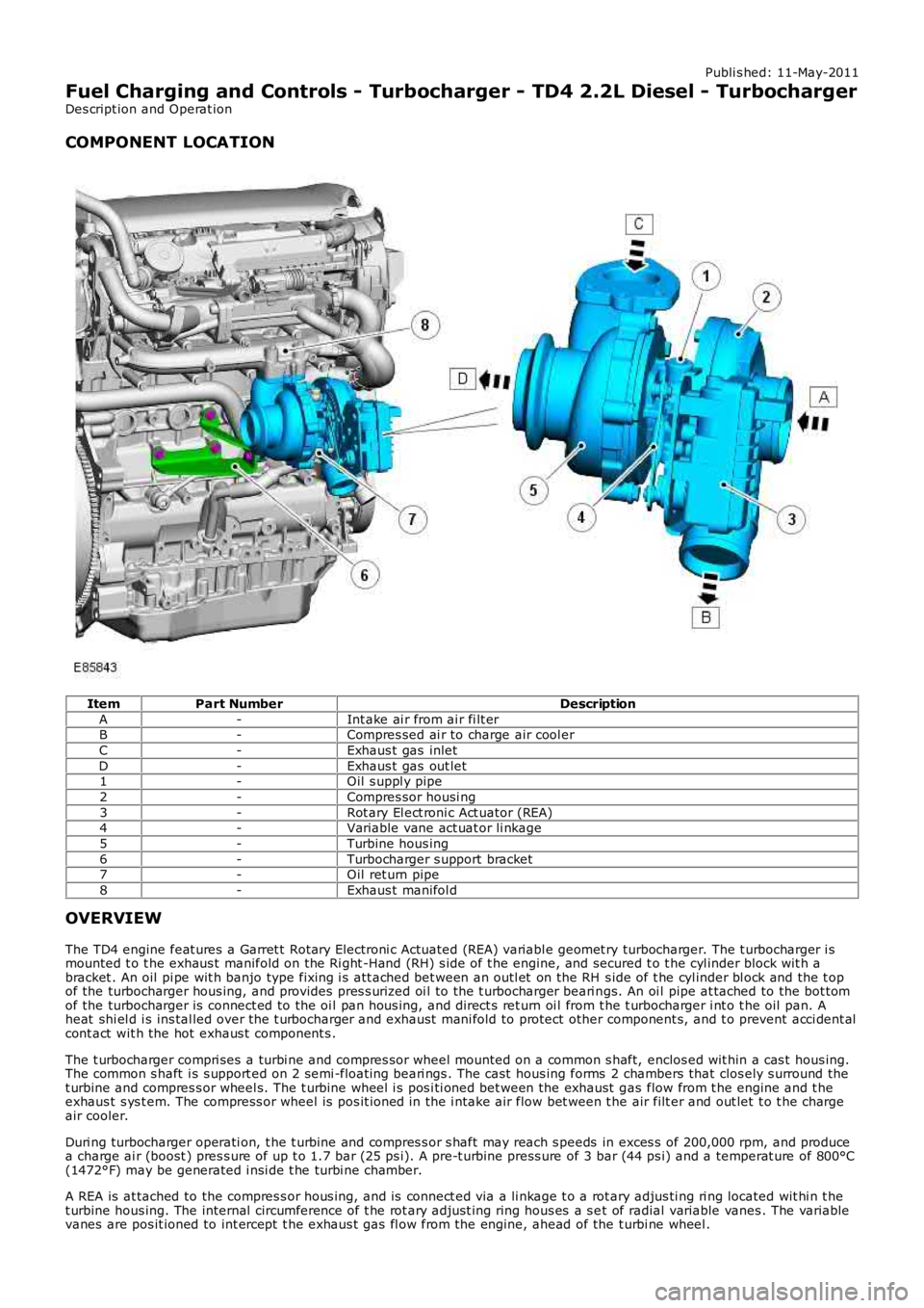
ItemPart NumberDescription
A-Int ake ai r from ai r fi lt erB-Compres sed ai r to charge air cool er
C-Exhaus t gas inlet
D-Exhaus t gas out let1-Oil s uppl y pipe
2-Compres sor housi ng
3-Rot ary El ect roni c Act uator (REA)4-Variable vane act uat or li nkage
5-Turbine hous ing
6-Turbocharger s upport bracket7-Oil ret urn pipe
8-Exhaus t manifol d
OVERVIEW
The TD4 engine feat ures a Garret t Rotary Electroni c Actuated (REA) variabl e geomet ry turbocharger. The t urbocharger i smounted t o t he exhaus t manifold on the Ri ght -Hand (RH) s ide of t he engine, and secured t o t he cyl inder block wit h abracket . An oil pi pe wit h banjo type fixing i s att ached bet ween an outl et on the RH s ide of t he cyl inder bl ock and the t opof the turbocharger hous ing, and provides pres s uri zed oi l to the t urbocharger beari ngs. An oi l pipe at tached to the bot tomof the turbocharger is connect ed to the oi l pan hous ing, and direct s ret urn oi l from t he t urbocharger i nt o t he oil pan. Aheat shi el d i s ins tal led over the t urbocharger and exhaust mani fold to protect other component s, and t o prevent acci dent alcont act wit h the hot exhaus t component s .
The t urbocharger compri ses a turbi ne and compres sor wheel mounted on a common s haft, enclos ed wit hin a cas t hous ing.The common s haft i s s upport ed on 2 semi -float ing beari ngs . The cast hous ing forms 2 chambers that clos ely s urround thet urbine and compres s or wheel s. The t urbine wheel i s pos i ti oned bet ween the exhaust gas flow from t he engine and t heexhaus t s ys t em. The compress or wheel is pos it ioned in the i ntake air flow bet ween t he air filt er and out let t o t he chargeair cooler.
Duri ng turbocharger operati on, t he t urbine and compres s or s haft may reach s peeds in exces s of 200,000 rpm, and producea charge ai r (boost ) pres s ure of up t o 1.7 bar (25 ps i). A pre-t urbine press ure of 3 bar (44 ps i) and a temperat ure of 800°C(1472°F) may be generated i nsi de t he turbi ne chamber.
A REA is at tached to the compres s or hous ing, and is connect ed via a li nkage t o a rotary adjus ti ng ri ng located wit hi n t het urbine hous ing. The internal circumference of t he rot ary adjus t ing ring hous es a s et of radial variable vanes . The variablevanes are pos it ioned to int ercept t he exhaus t gas fl ow from the engine, ahead of the t urbi ne wheel .
Page 1195 of 3229
Publi s hed: 11-May-2011
Electronic Engine Controls - I6 3.2L Petrol -
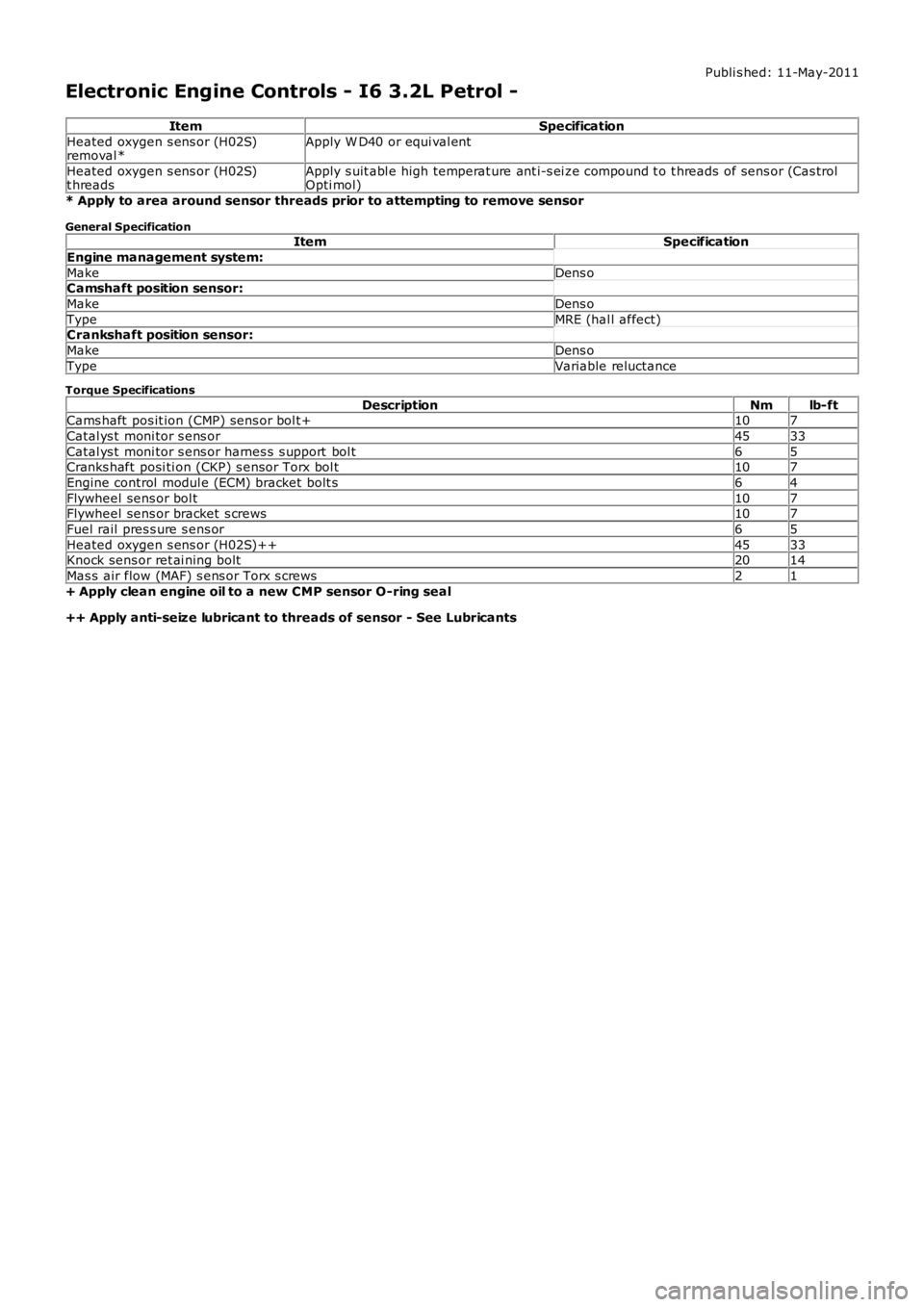
ItemSpecification
Heated oxygen s ens or (H02S)removal *Apply W D40 or equi val ent
Heated oxygen s ens or (H02S)t hreadsApply s uit abl e high temperat ure ant i-s ei ze compound t o t hreads of sens or (Cas trolOpti mol)
* Apply to area around sensor threads prior to attempting to remove sensor
General SpecificationItemSpecification
Engine management system:
MakeDens oCamshaft position sensor:
MakeDens o
TypeMRE (hal l affect)Crankshaft position sensor:
MakeDens o
TypeVariable reluctance
Torque Specifications
DescriptionNmlb-ftCams haft pos it ion (CMP) sens or bol t+107
Catal ys t moni tor s ens or4533
Catal ys t moni tor s ens or harnes s s upport bol t65Cranks haft posi ti on (CKP) s ensor Torx bol t107
Engine control modul e (ECM) bracket bolt s64
Flywheel sens or bol t107Flywheel sens or bracket s crews107
Fuel rail pres s ure s ens or65
Heated oxygen s ens or (H02S)++4533Knock sens or ret ai ning bolt2014
Mas s air flow (MAF) s ens or Torx s crews21
+ Apply clean engine oil to a new CMP sensor O-ring seal
++ Apply anti-seize lubricant to threads of sensor - See Lubricants
Page 1203 of 3229
and s ome are s uppli ed by ot her vehicle s ys tems .
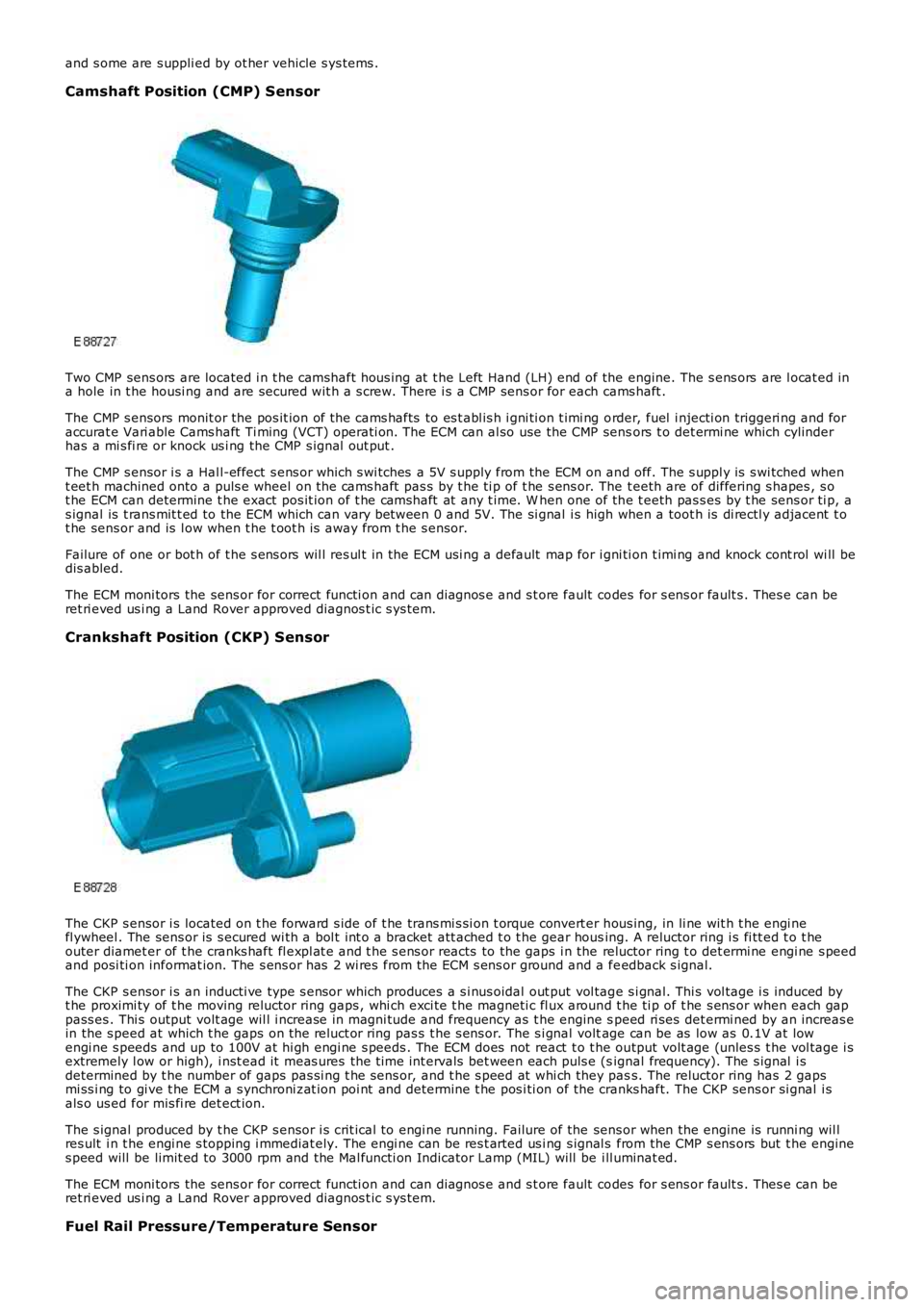
Camshaft Position (CMP) Sensor
Two CMP sens ors are located i n t he camshaft hous ing at t he Left Hand (LH) end of the engine. The s ens ors are l ocat ed ina hole in t he housi ng and are secured wit h a s crew. There i s a CMP sens or for each cams haft .
The CMP s ensors monit or the pos it ion of t he cams hafts to es t abl is h i gni ti on t imi ng order, fuel i njecti on triggeri ng and foraccurat e Vari able Cams haft Ti ming (VCT) operati on. The ECM can al so use the CMP sensors t o det ermi ne which cylinderhas a mi s fi re or knock us i ng the CMP s ignal out put .
The CMP s ensor i s a Hal l-effect s ens or which s wi tches a 5V s upply from the ECM on and off. The s uppl y is s wi tched whent eet h machined onto a puls e wheel on the cams haft pas s by t he ti p of t he s ens or. The t eeth are of differing s hapes , s ot he ECM can determine t he exact pos it ion of t he camshaft at any t ime. W hen one of the t eeth pas s es by t he sens or ti p, as ignal is t rans mit t ed to the ECM which can vary between 0 and 5V. The si gnal i s high when a toot h is di rectl y adjacent t ot he sens or and is l ow when t he t oot h i s away from t he s ensor.
Failure of one or bot h of t he s ens ors wil l res ul t in the ECM usi ng a default map for i gni ti on t imi ng and knock cont rol wi ll bedis abled.
The ECM moni tors the sens or for correct functi on and can diagnos e and s t ore fault codes for s ens or fault s . Thes e can beret ri eved us i ng a Land Rover approved diagnos t ic s ys tem.
Crankshaft Position (CKP) Sensor
The CKP s ensor i s located on t he forward s ide of t he trans mi s si on t orque convert er hous ing, in li ne wit h t he engi nefl ywheel . The sens or is s ecured wi th a bol t int o a bracket att ached t o t he gear housing. A reluctor ring i s fi tt ed t o t heouter diamet er of t he cranks haft fl expl at e and t he s ens or reacts to the gaps i n the reluctor ring t o det ermi ne engi ne s peedand posi ti on informat ion. The s ens or has 2 wi res from the ECM s ens or ground and a feedback s ignal.
The CKP s ensor i s an inducti ve type s ensor which produces a s i nus oidal out put vol tage s i gnal. Thi s vol tage i s induced byt he proximi ty of t he moving reluctor ring gaps , whi ch exci te t he magneti c fl ux around t he ti p of t he s ens or when each gappass es . Thi s output volt age wil l i ncrease in magni tude and frequency as t he engine speed ri ses det ermi ned by an increas ein the s peed at which t he gaps on t he reluct or ring pas s t he s ens or. The s i gnal voltage can be as low as 0.1V at lowengi ne s peeds and up to 100V at hi gh engi ne s peeds . The ECM does not react t o t he output volt age (unles s t he vol tage i sextremely l ow or high), i nst ead it meas ures the t ime int ervals bet ween each puls e (signal frequency). The s ignal i sdetermined by t he number of gaps pas si ng t he sens or, and t he s peed at whi ch they pass. The reluctor ring has 2 gapsmi ss i ng to gi ve t he ECM a s ynchroni zat ion poi nt and det ermi ne t he pos i ti on of the cranks haft. The CKP sens or si gnal i sals o us ed for mis fi re det ect ion.
The s ignal produced by t he CKP s ensor i s crit ical to engi ne running. Failure of the sens or when the engine is runni ng wil lres ult i n t he engi ne s topping i mmediat ely. The engi ne can be res t arted us i ng s ignal s from the CMP s ens ors but t he engines peed will be limit ed to 3000 rpm and the Mal functi on Indicator Lamp (MIL) will be ill uminat ed.
The ECM moni tors the sens or for correct functi on and can diagnos e and s t ore fault codes for s ens or fault s . Thes e can beret ri eved us i ng a Land Rover approved diagnos t ic s ys tem.
Fuel Rail Pressure/Temperature Sensor
Page 1206 of 3229
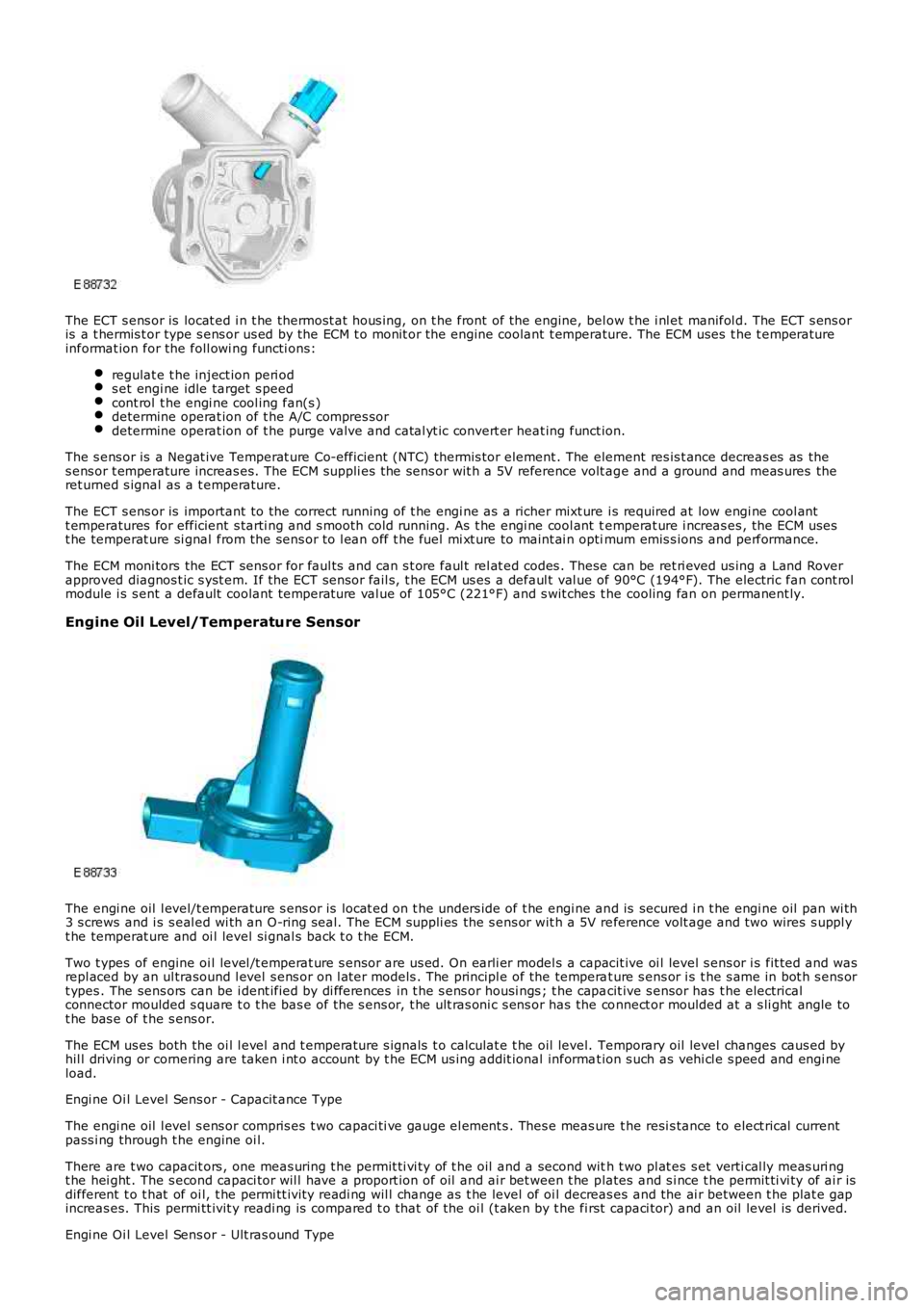
The ECT s ens or is locat ed i n t he thermost at hous ing, on t he front of the engine, below t he i nl et manifol d. The ECT s ens oris a t hermis t or type s ens or us ed by the ECM t o monit or the engine coolant t emperature. The ECM uses t he t emperatureinformat ion for the foll owi ng functi ons:
regulat e t he inject ion peri ods et engi ne idle target s peedcont rol t he engi ne cool ing fan(s )determine operat ion of t he A/C compres sordetermine operat ion of t he purge valve and catal yt ic convert er heat ing funct ion.
The s ens or is a Negat ive Temperat ure Co-efficient (NTC) thermis tor element . The element res is t ance decreas es as thes ens or t emperature increas es. The ECM suppli es the sens or wit h a 5V reference volt age and a ground and meas ures theret urned s ignal as a t emperature.
The ECT s ens or is important to the correct running of t he engi ne as a richer mixt ure i s required at low engi ne cool antt emperatures for efficient s tarti ng and s mooth cold running. As t he engi ne cool ant temperat ure i ncreas es , the ECM usest he temperat ure si gnal from the sens or to l ean off t he fuel mi xt ure to maint ai n optimum emis s ions and performance.
The ECM moni tors the ECT sens or for faul ts and can s t ore faul t rel at ed codes . These can be ret ri eved us ing a Land Roverapproved diagnos t ic s yst em. If the ECT sens or fail s, t he ECM us es a defaul t val ue of 90°C (194°F). The electric fan cont rolmodule i s s ent a default coolant temperat ure val ue of 105°C (221°F) and s wit ches t he cooling fan on permanent ly.
Engine Oil Level/Temperature Sensor
The engi ne oil l evel/t emperature s ens or is locat ed on t he unders ide of t he engi ne and is secured i n t he engi ne oil pan wi th3 s crews and i s s eal ed wi th an O-ring s eal. The ECM suppli es the s ens or wit h a 5V reference volt age and two wires s uppl yt he temperat ure and oi l level si gnal s back t o t he ECM.
Two t ypes of engine oi l level /t emperat ure s ensor are us ed. On earli er model s a capacit ive oi l level s ens or i s fit ted and wasrepl aced by an ul trasound l evel s ens or on l at er models . The principl e of the temperat ure s ens or i s t he s ame in bot h s ens ort ypes . The sens ors can be i dent ified by di fferences in t he s ens or housi ngs ; t he capacit ive s ensor has t he electricalconnector moulded s quare t o t he bas e of the s ens or, t he ult ras oni c s ens or has the connect or moulded at a s li ght angle tot he bas e of t he s ens or.
The ECM us es both the oi l l evel and t emperature s ignals t o calculat e t he oil level. Temporary oil level changes caus ed byhil l driving or cornering are taken i nt o account by t he ECM us ing addit ional informat ion s uch as vehi cl e s peed and engi neload.
Engi ne Oi l Level Sens or - Capacit ance Type
The engi ne oil l evel s ens or compris es t wo capaci ti ve gauge el ement s . Thes e meas ure the resi s tance to elect rical currentpass i ng through t he engine oi l.
There are t wo capacit ors , one meas uring t he permit ti vi ty of t he oil and a second with t wo pl at es s et verti cal ly meas uri ngt he hei ght . The s econd capaci tor wil l have a proport ion of oil and ai r bet ween t he plates and s i nce t he permit ti vi ty of ai r isdifferent t o t hat of oi l, t he permi tt ivit y readi ng wil l change as t he level of oi l decreas es and the ai r between t he plat e gapincreas es. This permi tt ivit y readi ng is compared t o t hat of the oi l (t aken by t he first capaci tor) and an oil level is derived.
Engi ne Oi l Level Sens or - Ult ras ound Type
Page 1217 of 3229
To s top the engine t he s t op/s tart but ton must be pres sed. Forcibly removing t he remote hands et from t he s tart controlmodule will not s top the engine. On models wit h automat ic t rans mi ss i on, once the engi ne has st opped the remotehands et wil l not be releas ed by t he s tart cont rol module unt il the trans mi s si on s el ect or lever is i n t he Park (P) pos i ti on.
Throttle Control
The ECM controls t he posi ti oni ng of the throt t le di sc i n t he electric t hrot tl e us ing i nformat ion from t he APP s ens or and t heTP s ensor. Dat a from t he A/C pres sure s ens or, TCM, ECT s ens or, MAF s ensor and t he MAP/IAT s ensor i s als o us ed todetermine t he correct t hrot tl e cont rol .
The t wo Hall effect sens ors i n t he TP s ens or are des ignat ed 1 and 2. Both sens ors out put an i ncreasi ng vol tage as thet hrott le di s c angl e increas es. Smal l air fl ows t hrough the throt tl e requi re comprehens ive regul at ion, t herefore the vol tageri s e in one of the s ensors increas es more quickl y t han the ot her s ens or whi ch gives accurat e cont rol of t he thrott le andensure t he thrott le di sc is i n t he correct posi ti on.
The ECM moni tors the si gnal s from bot h s ens ors to ens ure they are wit hin the minimum and maximum t hres hol ds and thatt he si gnal s corres pond t o the same thrott le di sc pos it ion. If there is a difference in the si gnal s the ECM us es a defaultt hrott le si gnal calculated from t he electric t hrot tl e load, engi ne s peed and ai r pres s ure and t emperature s ignals . Thes ens or whose out put s ignal i s clos est t o t he calcul ated t hrot tl e dis c angle will be us ed as t he correct output . A faul t codewil l be recorded for the ot her s ens or and t his can be read us ing a Land Rover approved di agnos ti c s ys t em. The ECM t henmonit ors t he remaining s ens or out put s i gnal and compares it agains t t he cal cul ated value. If a difference i n thecomparis on occurs t he ECM wi ll dis count t he output from bot h s ens ors and dis abl e t he electric t hrot tl e cont rol and revert toa l imp home mode. The throt t le di sc has s prings for opening and clos ing and t he ECM can meas ure the l oad appl ied byt hes e s pri ngs for a l oad s ignal . If a fault occurs whi ch prevent s t he damper mot or from being operat ed, the s prings ret urnt he throt t le di sc to a pos i ti on which all ows a t hrot tl e openi ng large enough t o all ow t he vehi cle t o driven, but wi th reduceddri ve abi li ty.
Throt tl e Adapt ions
The ECM has a learning adapti on which al lows t he ECM t o calculate the preci s e cont rol required for t he elect ric throt t ledamper motor. The adapti on process is performed when the ignit ion i s on and t he engine is not runni ng. The t hrot tl e dis cis moved by the damper mot or to t he fully cl osed pos it ion and t he ECM records t he val ues out put by the TP sens orpotenti ometers.
If the permanent batt ery supply t o t he ECM has been removed, t hen previous adapt ions wi ll have been los t. If adapt ionsare st ored, t hen the ECM compares the s t ored adapti on val ues wit h t he current t hrottle angl e and us es an average of thes tored and current values t o create the new adapt ion value.
If the el ect ri c throt t le unit has been repl aced, t he power s upply mus t be removed from t he ECM t o eras e al l previousl ys tored adapt ion values .
Fuel Pressure Regulation
Fuel pres s ure regulati on is cont roll ed by t he ECM t o res pond t o fuel pres s ure demand and provi des s t epl ess cont rol of the
pump output us ing t he FPDM t o control t he pump operat ion. The ECM can vary t he fuel pres s ure to bet ween 55.1 l bf/in2
(3.8 bar) and 72.5 lbf/i n2 (5 bar). The hi gh pres s ure i s only us ed in ext reme condit ions s uch as heavy engine loads andengi ne s tarts .
The ECM us es t he si gnal s from the fuel rail pres s ure/temperat ure s ens or t o det ermi ne informat ion regardi ng t he pres sureand t emperature of the fuel and provi de precis e i njecti on periods , improvi ng engi ne s tarti ng under all condit ions. Theadvant age of controll ing t he fuel pump output pres s ure are t hat pump power consumpt ion is reduced, loweri ng the load ont he power s upply s yst em and reduci ng fuel cons umpt ion, improved s ervi ce life of t he pump and reduced fuel pump nois e.
• NOTE: W hen t he i gni ti on is swi tched off t he FPDM reduces t he fuel li ne pres s ure regul at ion to 29 lbf/in2 (2 bar) to hel preduce inject or leakage.
Knock Control
Knock occurs i n a cyli nder when t he fuel and air s elf i gni tes at t he wrong ti ming. This can occur eit her before or after t hes park i s produced. The fuel mi xt ure can ignit e in different areas of t he combus t ion chamber and res ul ts in a fas tcombus t ion proces s creati ng s everal s eparat e fuel combus t ions which t oget her combi ne to produce a mechani cal knockings ound. The s ounds produce a certain type of vibrat ion through t he engine cylinder block and thes e are detected by t heknock s ensors . The two knock s ens ors det ect knocks on cyl inders 1, 2 and 3 and 4, 5 and 6 respecti vel y.
The vibrat ions act upon the peizo crys t als wi thi n t he sens ors whi ch res ult s in a volt age bei ng produced whi ch is sens ed byt he ECM. The ECM, us ing the CMP sens ors and t he CKP s ensor, can det ermi ne which cylinder(s ) are knocking. The ECM isable t o fil ter t he s ignal t o det ect vibrat ions creat ed duri ng normal engi ne operati on and dis card t hem from the knockdetecti on. The i gni ti on t imi ng is gradual ly advanced unti l the knocki ng is det ect ed once agai n.
Once the ECM has determined knocking is occurri ng usi ng other input s s uch as cat al yti c convert er temperat ure for exampl ein addi ti on to the s i gnal s from t he knock s ens ors , it first retards the ignit ion t imi ng and s ubs equent ly ri chens t he air/fuel i frequired.
Variable Camshaft Timing (VCT) Control
The inl et cams haft i s cont rol led by t he ECM us ing the VCT s olenoid. The exhaus t camshaft is fixed and i ts ti ming cannotbe changed.
Both cams haft s are dri ven i ndirect ly from the cranks haft via a chai n. The chain is driven from a s haft in the gear hous i ngas sembl y.For addit ional informat ion, refer t o: Engi ne - 3.2L (303-01, Descripti on and Operat ion).The VCT all ows t he ECM t o adus t t he inl et cams haft pos it ion i n rel ati on to the cranks haft , al tering t he t imi ng of theopeni ng and clos ing of t he inlet and exhaus t valves rel ati ve to the cranks haft posi ti on. Thi s allows the ECM to provideincreas ed engi ne performance, i mproved i dl e quali ty and reduced emi ss i ons .
Page 1549 of 3229
Publi s hed: 27-May-2011
Fuel System - General Information - Fuel Tank Draining
General Procedures
• W ARNINGS:
Place t he vehi cle i n a wel l vent ilat ed, quarant ined area and arrange ' No Smoki ng/Petrol Fumes ' si gns about t hevehi cl e.
Do not carry or operate cel lular phones when working on or near any fuel rel at ed component s. Hi ghl y flammablevapors are al ways pres ent and may ignit e. Fai lure to foll ow t hese ins truct ions may res ul t in pers onal injury.
Do not s moke or carry li ght ed t obacco or open flame of any type when worki ng on or near any fuel relat edcomponents . Hi ghl y fl ammable vapors are al ways present and may i gnit e. Fail ure t o foll ow t hes e i nst ructi ons may res ult inpers onal i njury.
The s pil ling of fuel is unavoi dabl e duri ng thi s operati on. Ens ure t hat all neces s ary precauti ons are t aken to preventfi re and expl os i on.
CAUTION: Before dis connecti ng or removing component s , ens ure the area around t he joint faces and connect ions areclean. Pl ug open connect ions t o prevent cont aminat ion.
• NOTE: It is pos s ible that up t o 18 l it res of fuel may be left i n t he tank after drai ning.
Open t he fuel fill er door and remove the cap.1.
Di sconnect t he bat t ery ground cable.
Refer t o: Specificati ons (414-01 Bat tery, Mount ing and Cables ,Speci fi cat ions ).
2.
Connect t he fuel t ank drain equipment ground cable t o t he vehi cle.3.
4. W ARNING: Fuel may s t ill be present i n t he fuel tank afterdrai ning.
Remove t he fuel from t he fuel t ank, via the fil ler neck, us ing t he fuelt ank draining equi pment . Fol low the manufact urer's operati ngi ns t ructi ons .
4.
To i nst all , revers e t he removal procedure.5.