2006 LAND ROVER FRELANDER 2 fuel type
[x] Cancel search: fuel typePage 1552 of 3229
Publi s hed: 11-May-2011
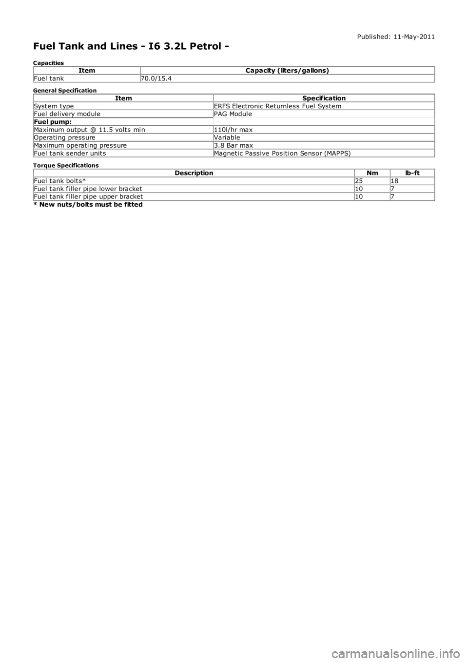
Fuel Tank and Lines - I6 3.2L Petrol -
C apacitiesItemCapacity (liters/gallons)
Fuel t ank70.0/15.4
General Specification
ItemSpecification
Syst em typeERFS Electronic Ret urnles s Fuel Sys temFuel del ivery modulePAG Modul e
Fuel pump:
Maximum output @ 11.5 volt s mi n110l/hr maxOperat ing press ureVariable
Maximum operati ng pres s ure3.8 Bar max
Fuel t ank s ender unit sMagneti c Pass ive Pos it ion Sens or (MAPPS)
Torque SpecificationsDescriptionNmlb-ft
Fuel t ank bolt s*2518
Fuel t ank fi ll er pi pe lower bracket107Fuel t ank fi ll er pi pe upper bracket107
* New nuts/bolts must be fitted
Page 1588 of 3229
prot ect ion t ray is s ecured wit h i ntegral cli ps on the ins ide of t he tray t o s tuds along t he underfl oor.
CAUTION: The fuel l ine quick-fit t ype connect or is a new des ign connector i ns t alled to the TD4 vehicle. Duringmaint enance procedures t he quick-fi t t ype connect or must be releas ed and connected correct ly to prevent fuel l eakage.Us e t he correct met hod det ailed in t he rel evant s ect ion of t he Servi ce Repair Manual (SRP) t o rel eas e and connect t heconnector. Incorrect operati on of the qui ck-fi t type connector wi ll res ult in damage t o t he connector and caus e fuelleakage.
The quick-fit t ype fuel connect or is not a s elf s eali ng connector, and will not prevent fuel fl ow when dis connected.
The fuel s uppl y and ret urn lines are connected at each end wit h a qui ck-fi t type connect or. The connector is nots elf-s eal ing and will not prevent fuel fl ow when t he fuel li ne is separat ed.
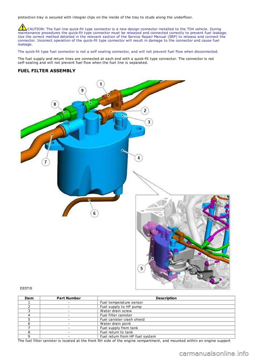
FUEL FILTER ASSEMBLY
ItemPart NumberDescription
1-Fuel t emperat ure s ensor
2-Fuel s upply t o HP pump3-W at er drain screw
4-Fuel fil ter cani s ter
5-Fuel canis ter cras h s hiel d6-W at er drain poi nt
7-Fuel s upply from tank
8-Fuel return to tank9-Fuel return from HP fuel s ys t em
The fuel filt er cani st er is l ocat ed at the front RH si de of the engi ne compartment , and mount ed wi thi n an engine s upport
Page 1589 of 3229
bracket . A cras h s hiel d is ins tal led t o prot ect t he filt er cani st er in the event of a front al impact. The fil ter cani s ter ismanufactured from heat res is t ant and flame-proof durable pl ast ic, and cont ains a paper t ype fil ter element .
The fuel t emperature s ens or is incorporated wit hin t he fuel s uppl y li ne connecti on on t he fuel fi lt er canis t er. The s ens orprovides t he ECM wi th a s ignal vol tage t hat is proporti onal t o the act ual fuel t emperat ure. The s ignal i s us ed by the ECMin conjuncti on wi th ot her vehicle s ens ors , t o cal cul ate the actual fuel pres s ure requi red i n t he HP fuel rail .For addit ional informat ion, refer t o: Electroni c Engi ne Controls - 2.2L Dies el (303-14 El ect ronic Engine Cont rols - 2.2LDies el, Des cript ion and Operat ion).
A bl eed screw and drai n point are locat ed on t he fi lt er canis t er. The bleed s crew allows wat er cont ent in t he fuel t o bedrai ned off during servi ce int ervals .
Fuel Filter Pre-Heat Function
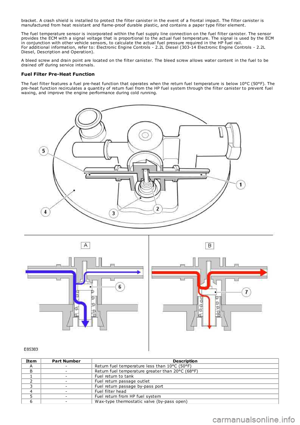
The fuel filt er feat ures a fuel pre-heat functi on that operates when the return fuel t emperature is bel ow 10°C (50°F). Thepre-heat funct ion reci rculat es a quant it y of ret urn fuel from t he HP fuel s ys tem through the fil ter cani s ter t o prevent fuelwaxing, and improve the engine performance during cold runni ng.
ItemPart NumberDescriptionA-Ret urn fuel t emperat ure l es s t han 10°C (50°F)
B-Ret urn fuel t emperat ure great er than 20°C (68°F)
1-Fuel return t o t ank2-Fuel return pas sage out let
3-Fuel return pas sage by-pas s port
4-Fuel fil ter head5-Fuel return from HP fuel s yst em
6-W ax-type t hermos tat ic valve (by-pas s open)
Page 1590 of 3229
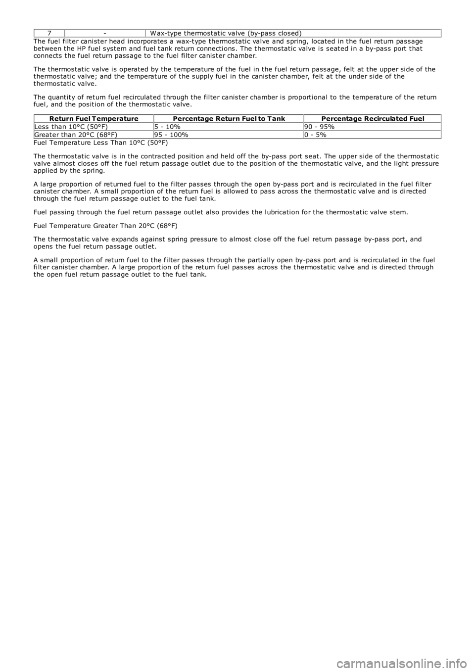
7-W ax-type t hermos tat ic valve (by-pas s clos ed)
The fuel filt er cani st er head incorporates a wax-t ype thermos t ati c val ve and s pring, located i n t he fuel ret urn pas s agebetween t he HP fuel s ys tem and fuel t ank return connecti ons . The t hermos tat ic valve i s s eat ed i n a by-pas s port t hatconnects t he fuel return pass age t o t he fuel fi lt er canis t er chamber.
The t hermos tat ic valve i s operated by the t emperat ure of t he fuel in the fuel return pass age, felt at t he upper si de of thet hermos tat ic valve; and the temperat ure of t he s uppl y fuel in the canis t er chamber, felt at t he under s ide of t het hermos tat ic valve.
The quant it y of ret urn fuel recirculat ed t hrough the fil ter canis ter chamber i s proport ional to the temperat ure of t he ret urnfuel , and the pos it ion of t he thermost ati c valve.
Return Fuel T emperaturePercentage Return Fuel to T ankPercentage Recirculated Fuel
Less than 10°C (50°F)5 - 10%90 - 95%
Great er than 20°C (68°F)95 - 100%0 - 5%Fuel Temperat ure Les s Than 10°C (50°F)
The t hermos tat ic valve i s in the contract ed posi ti on and held off the by-pas s port seat . The upper s ide of t he thermost ati cvalve almos t clos es off t he fuel ret urn pas s age outl et due t o t he pos it ion of t he thermost ati c val ve, and t he l ight pres sureappl ied by the s pri ng.
A l arge proporti on of ret urned fuel t o the fi lt er pas s es through t he open by-pas s port and is recircul at ed i n the fuel fi lt ercani st er chamber. A s mall proporti on of the return fuel is al lowed t o pas s acros s the thermos t ati c val ve and is di rectedt hrough the fuel return pas sage out let to the fuel tank.
Fuel pas si ng t hrough the fuel ret urn pas sage out let als o provi des the l ubricati on for t he t hermos tat ic valve s t em.
Fuel Temperat ure Greater Than 20°C (68°F)
The t hermos tat ic valve expands agains t s pring pres sure t o almos t clos e off t he fuel return pas s age by-pas s port , andopens the fuel return pass age outl et.
A s mal l proporti on of ret urn fuel to t he fil ter pass es t hrough t he parti all y open by-pas s port and is reci rculat ed in the fuelfi lt er canis t er chamber. A large proport ion of t he ret urn fuel pas s es across the t hermos tat ic valve and is direct ed t hrought he open fuel ret urn pas sage out let t o the fuel tank.
Page 1613 of 3229
A CANCEL s wit ch.
The s ys t em al so uses t he fol lowi ng:
The ECMThe s toplamp s wit ch.The APP s ens or
The ECM controls t he s et speed by modi fying engine speed/t orque and reques ti ng gear changes from t he transmis si on(aut omati c variant s only).
The s peed control sys t em als o us es i nput s from t he brake pedal swit ch, t he APP s ens or, t he ECM and t he ABS controlmodule.
The s peed control is operat ed by t he dri ver us ing only the s t eering wheel s wit ches . W hen s peed is act ive, the ECMregulat es the PW M s i gnal s to the fuel injectors t o adjus t the fuel supply as required to maintai n t he s et s peed.
Duri ng s peed control operat ion, t he ECM control s vehicle s peed by adjus ti ng fuel inject ion durat ion and ti ming. W hen t heaccelerator pedal i s pres s ed wit h s peed cont rol act ive, t he ECM output s a calculated throt tl e angle s i gnal in place of theact ual throt t le angle si gnal s produced by the APP s ens or. The cal cul ated t hrot tl e angle i s deri ved from fuel demand.
CONTROL SWITCHES
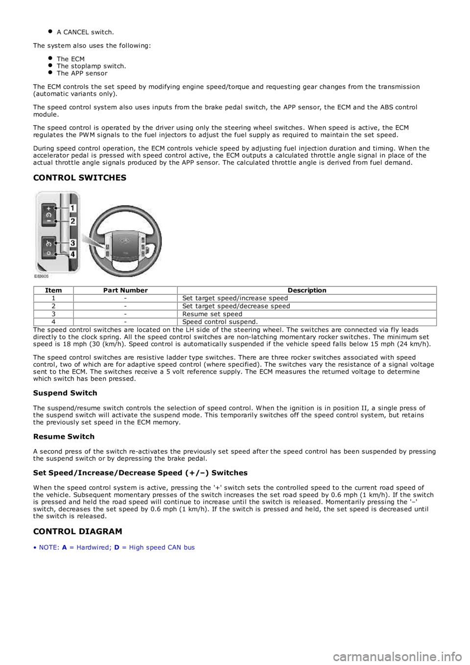
ItemPart NumberDescription1-Set target s peed/increas e s peed
2-Set target s peed/decreas e s peed
3-Resume set s peed4-Speed control sus pend.
The s peed control swit ches are located on t he LH s i de of the s t eering wheel. The s witches are connect ed via fly leadsdirect ly t o t he clock s pring. All t he s peed cont rol s wit ches are non-lat chi ng momentary rocker swit ches . The mini mum s ets peed is 18 mph (30 (km/h). Speed cont rol is aut omati cal ly s us pended i f the vehicle speed falls bel ow 15 mph (24 km/h).
The s peed control swit ches are res is t ive l adder type s wi tches. There are t hree rocker s wit ches as s oci at ed wi th speedcont rol , two of whi ch are for adapt ive s peed cont rol (where s peci fi ed). The s wit ches vary the resi s tance of a s ignal vol tages ent t o t he ECM. The s wit ches recei ve a 5 volt reference s upply. The ECM meas ures t he ret urned volt age to det ermi newhich s wi tch has been pres s ed.
Suspend Switch
The s uspend/resume swit ch controls t he s electi on of speed control. W hen t he i gni ti on is i n pos it ion II, a si ngle pres s oft he sus pend s wit ch wil l act ivate the s us pend mode. This temporaril y s wit ches off the s peed cont rol s yst em, but ret ai nst he previousl y s et s peed i n t he ECM memory.
Resume Switch
A s econd pres s of the s wi tch re-acti vat es the previousl y s et speed after t he s peed control has been s us pended by pres s ingt he sus pend s wit ch or by depres s ing the brake pedal.
Set Speed/Increase/Decrease Speed (+/–) Switches
W hen t he s peed cont rol s ys t em i s act ive, pres s ing t he '+' s wi tch s ets the controlled speed t o t he current road speed oft he vehi cl e. Subs equent moment ary pres s es of the s wi tch i ncreas es t he s et road s peed by 0.6 mph (1 km/h). If t he s wit chis pres sed and hel d the road s peed wil l conti nue to increas e unti l the s wi tch i s releas ed. Moment ari ly press i ng the '–'s wit ch, decreas es the s et s peed by 0.6 mph (1 km/h). If t he s wit ch is press ed and held, t he s et speed i s decreas ed unt ilt he swit ch is released.
CONTROL DIAGRAM
• NOTE: A = Hardwi red; D = Hi gh s peed CAN bus
Page 1775 of 3229
s ervice i nt erval data and res tore the set ti ngs in t he new i nst rument clus t er.
W hen a new ins t rument clus ter is ins tall ed, the Land Rover approved diagnost ic sys tem is used t o t rans fer t he carconfigurat ion fil e data from t he CJB to the replacement i nst rument clus t er. Vehicle coding dat a s uch as engine type andmarket i s ret ri eved and us ed t o updat e t he repl acement ins t rument clus ter.
The car confi gurati on fi le will al so need to be updat ed usi ng the Land Rover approved di agnos ti c s ys t em i f the vehicle ismodified i n s ervice from it s original factory s pecificati on. Thi s can include fit ti ng non-s tandard wheels and/or t ires , oropti onal acces s ory dealer fi t components wit h an elect rical int erface.
GEAR SHIFT INDICATOR - FROM 2010 MY
OVERVIEW
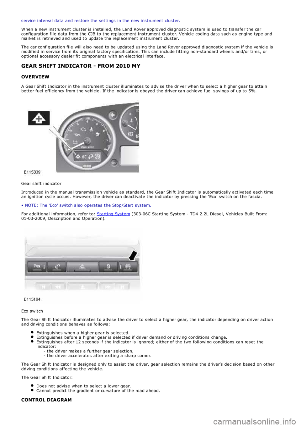
A Gear Shift Indicator i n t he ins trument cl ust er il lumi nat es to advi se the driver when to s el ect a higher gear t o att ainbett er fuel efficiency from t he vehi cl e. If t he indi cat or i s obeyed the driver can achieve fuel s avings of up to 5%.
Gear shi ft i ndi cat or
Int roduced in the manual transmis si on vehi cle as s t andard, t he Gear Shi ft Indicator is aut omati cal ly act ivated each t imean i gni ti on cycle occurs . However, the driver can deacti vat e t he indi cat or by press ing the ‘Eco’ s wit ch on t he fas cia.
• NOTE: The ‘Eco’ swi tch al so operates t he Stop/St art s ys tem.
For addit ional informat ion, refer t o: Starti ng Sys t em (303-06C Starti ng Syst em - TD4 2.2L Di es el, Vehicles Bui lt From:01-03-2009, Descripti on and Operat ion).
Eco s wit ch
The Gear Shi ft Indicat or il lumi nat es t o advi se the driver to s el ect a higher gear, the i ndi cat or depending on driver act ionand dri vi ng condi ti ons behaves as fol lows :
Exti nguis hes when a hi gher gear is s elect ed.Exti nguis hes before a hi gher gear is s elected i f dri ver demand or dri vi ng condi ti ons change.Exti nguis hes aft er 12 s econds if t he i ndi cat or is i gnored; ei ther of the two foll owing condi ti ons can res et theindicat or:- t he dri ver makes a furt her gear s elect ion,- t he dri ver accel erates after exit ing a sharp corner.
The Gear Shi ft Indicat or is des igned only to as s is t t he dri ver, gear s electi on remains the driver’s deci si on based on otherdri vi ng condi ti ons affecti ng t he vehi cl e.
The Gear Shi ft Indicat or:
Does not advis e when to sel ect a l ower gear.Cannot predi ct t he gradi ent or curvature of the road ahead.
CONTROL DIAGRAM
Page 1827 of 3229
Publi s hed: 11-May-2011
Battery, Mounting and Cables -
General SpecificationItemSpecification
Battery - All models:
TypeExide H7Capaci ty80Ah/700CCA
Res erve capacit y125 minutes
Battery Disconnect/C onnect
CAUTION: The vehicle s t atus and batt ery condit ion mus t be es t abl is hed before att empti ng bat t erydis connect/connect . Reference mus t be t hen made t o t he fol lowing table to es t abl is h t he rel evant procedure t o befol lowed.
• NOTE: Vehicles fit ted wit h a fuel fired boos t er heat er will requi re a 5 mi nute wait before tel es t art funct ion wi ll operate.Cycl e t he ignit ion off->on->off. W ai t 5 mi nutes t o all ow fuel fired boos t er heat er to s t ore vehicle confi gurati onparamet ers .
Vehicle statusBattery chargedBattery discharged
ProcedureProcedure
Engine runni ng1Vehicle powered down, l ocked and alarmed23
Vehicle unl ocked45
Procedure 1
Disconnect batteryConnect battery1. Apply parki ng brake oralt ernat ively, chock wheels1. Ens ure that all el ect ri cal loads are s wit ched O FF
2. Swit ch off i gni ti on andremove the remote cont rol.2. Connect bat t ery l eads - GROUND lead l ast
3. W ai t 2 mi nut es for enginemanagement sys tem t o 'powerdown'
3. Swit ch on ignit ion
4. Open t he hood4. Reset radi o s tat ion preset but tons .
5. Dis connect batt ery - GROUNDl ead firs t5. Reset clock
6. Reset elect ric window one-t ouch facili ty. Power window up t o hard s top, rel eas es wit ch, reapply and hol d for 1 s econd (relay i n door wil l cl ick). Lower window t o s top,reapply and hold for one s econd. One t ouch s hould now work
Procedure 2
Disconnect batteryConnect battery
1. Unlock t he vehi cl e and dis armt he alarm us ing t he remotecont rol
1. Ensure t hat al l el ect ri cal l oads are s wit ched OFF
2. Apply parki ng brake oralt ernat ively, chock wheels2. Connect batt ery l eads - GROUND l ead las t
3. W ai t 2 mi nut es for enginemanagement sys tem t o 'powerdown'
3. Swit ch on i gni ti on
4. Open t he hood4. Res et radio s t ati on pres et but tons .
5. Dis connect batt ery - GROUNDl ead firs t5. Res et cl ock
6. Res et el ect ri c window one-touch facil it y. Power window up to hard s top, rel eases wit ch, reappl y and hold for 1 s econd (rel ay in door wil l cl ick). Lower window t o s top,reapply and hol d for one s econd. One t ouch should now work
• NOTE: 1. Disconnect battery - If the remot e cont rol is not funct ioning, it will be necess ary to manual ly unlock thevehi cl e us ing t he key.
Procedure 3
Disconnect batteryConnect battery1. Unlock t he vehi cl e from the LH frontdoor us i ng the key1. Ens ure t hat al l electrical l oads are s wi tched OFF
2. Enter t he vehi cl e, and dock t heremote control to si lence the al arm.2. Connect batt ery leads - GROUND l ead las t
3. Remove t he remot e cont rol and wai t2 minutes for engi ne managements yst em to 'power down'
3. Swi tch on i gni ti on
4. Open t he hood4. Res et radio st ati on pres et but t ons .
5. Dis connect batt ery - GROUND leadfirst5. Res et cl ock
6. Res et el ect ri c wi ndow one-touch facil it y. Power wi ndow up to hard s t op,release s wit ch, reapply and hol d for 1 second (relay i n door wil l cl ick). Lowerwi ndow to s top, reapply and hold for one s econd. One t ouch s hould now work
• NOTE: 1. Connect battery - If there is ins uffi cient capacit y in the bat tery to di s arm the al arm, t he alarm may sound onreconnect ion of t he bat t ery - St ep 2 wi ll dis arm t he alarm
Procedure 4
Disconnect batteryConnect battery
Page 2753 of 3229
33
Filling station information
R
Filling station informationFILLING STATION INFORMATION
Fuel filler flap
Fuel filler flap location A small arrow on the fuel gauge
indicates which side of the vehicle
the fuel filler flap is located.
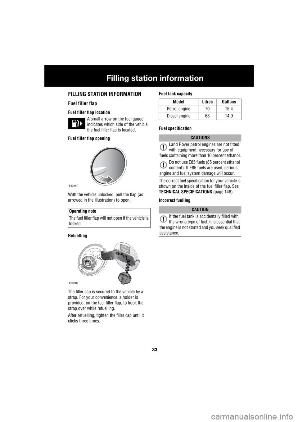
Fuel filler flap opening
With the vehicle unlocked, pull the flap (as
arrowed in the illustration) to open.
Refuelling
The filler cap is secured to the vehicle by a
strap. For your conv enience, a holder is
provided, on the fuel filler flap, to hook the
strap over while refuelling.
After refuelling, tighten the filler cap until it
clicks three times. Fuel tank capacity
Fuel specification
The correct fuel specification for your vehicle is
shown on the inside of the fuel filler flap. See
TECHNICAL SPECIFICATIONS (page 146).
Incorrect fuelling
Operating note
The fuel filler flap will not open if the vehicle is
locked.
E83705
E83217
E83218
Model Litres Gallons
Petrol engine 70 15.4
Diesel engine 68 14.9
CAUTIONS
Land Rover petrol engines are not fitted
with equipment necessary for use of
fuels containing more than 10 percent ethanol.
Do not use E85 fuels (85 percent ethanol
content). If E85 fuels are used, serious
engine and fuel system damage will occur.
CAUTION
If the fuel tank is accidentally filled with
the wrong type of fuel, it is essential that
the engine is not starte d and you seek qualified
assistance.