Page 217 of 234
Roof Rack Vehicle Converter Special Fit
DescriptionItem
Rear edge of Cab Doors 'B'-Pillar1
100Kg Maximum2
Maximum roof rack length Short Wheel Base:2500mm / Long Wheel Base 3282mm3
Maximum Load Height 300mm4
Drain Channel5
Roof Rack Supports each side, Short Wheel Base: 3 foot attachments / Long Wheel Base
4 foot attachments
6
Maximum 75Kg per attachment foot worst case7
FordTransit 2006.5 (April 2006–)
Date of Publication: 12/2006
5 Body and Paint
217123564E75917
Page 218 of 234
5.8 Air Bag Supplemental Restraint System (SRS)
5.8.1 Air Bags
Front Seats
Side airbags are not compatible with swiveling
front seats.
Do not specify the base vehicle with side airbags
when planning to retrofit a swiveling device on
the front seats and/or an armrest on the outer
side of the front seats, this may affect the function
and/or deployment of the side airbags.
The airbag sensors for side airbags are located
nearby the bottom of the B-pillar
WARNING: Modifications or
reinforcements in the area of the
sensors may affect the side airbag
fire timing and result in uncontrolled
side air bag deployment.
Please note that vehicles not equipped with side
airbags but equipped with front airbags only are
not affected.
Drilling or grinding operations in this area are only
permitted when battery cables are disconnected.
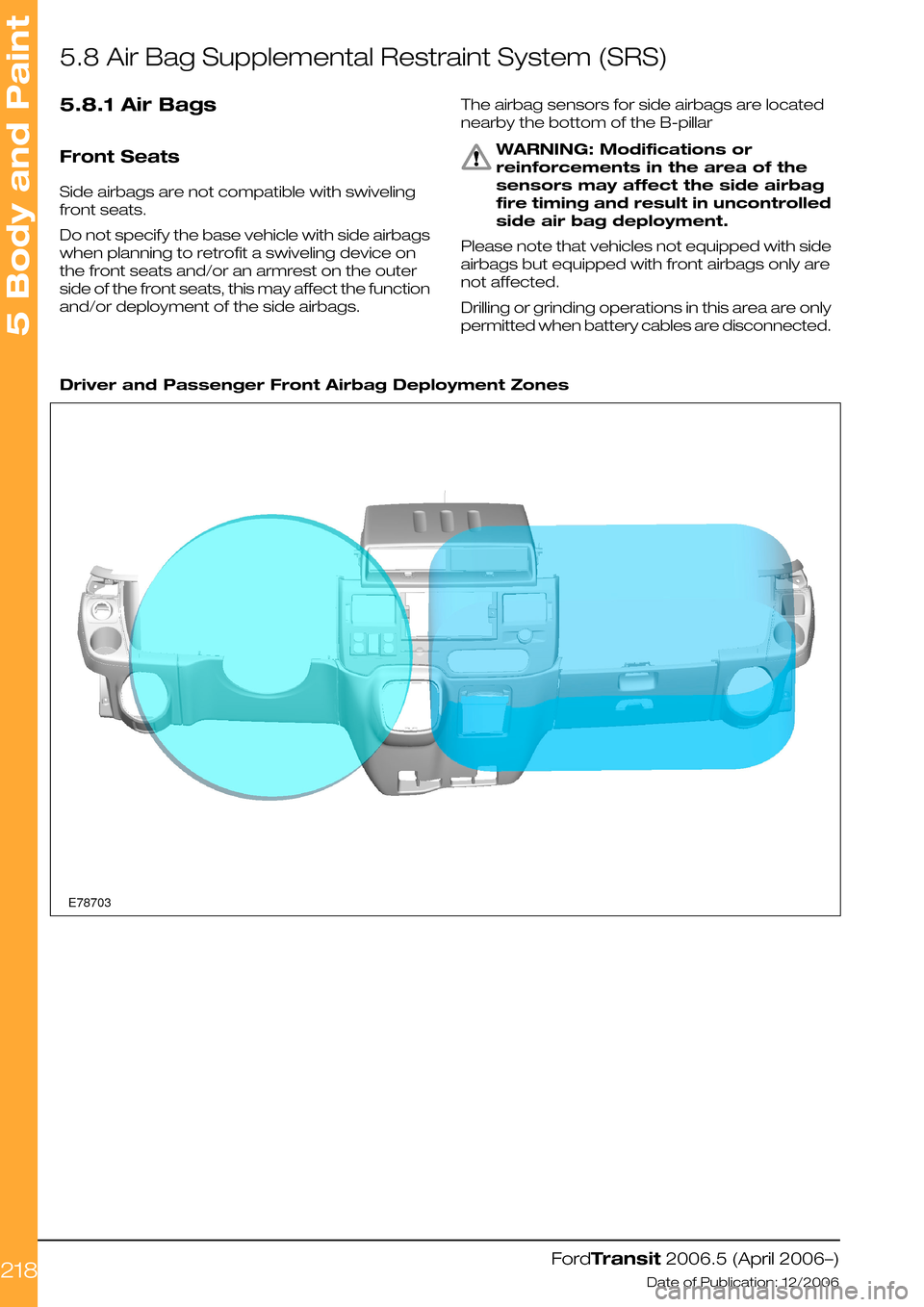
Driver and Passenger Front Airbag Deployment Zones
FordTransit 2006.5 (April 2006–)
Date of Publication: 12/2006
5 Body and Paint
218E78703
Page 219 of 234
Position of the Side Air Bag Sensor on the Left Hand Side
FordTransit 2006.5 (April 2006–)
Date of Publication: 12/2006
5 Body and Paint
219E74470
Page 220 of 234

5.9 Safety Belt System
WARNING: Follow removal and
installation procedures for the seat
belt system to ensure correct
function of the restraints system.
The removal and reinstallation of the seat belt,
strainer or any component of the seat belt system
should be avoided. In case the removal and
re-installation system is required during the
conversion, however, follow the guidelines for
removal and installation of the seat belt system
as described in the workshop manual. Please
consult your local National Sales Company
representative for further information
When removing the seat belt system, a seat belt
webbing forked retainer should be applied to the
webbing 200mm below the webbing button stop.
This prevents a situation where all the webbing
runs back into the retractor and the retractor
becomes locked.
When reinstalling, fit the retractor to the body first
and gently pull the webbing out of the retractor
to allow fitment of the D loop. Then remove the
forked retainer. If the retractor is locked, allow a
small amount of webbing to reel back into the
retractor to allow the webbing lock to release. Do
not attempt to release the retractor by pulling on
the webbing with significant force or by manually
interfering with the locking mechanism.
FordTransit 2006.5 (April 2006–)
Date of Publication: 12/2006
5 Body and Paint
220
Page 221 of 234

5.10 Corrosion Prevention
5.10.1 General
Avoid drilling into closed frame body members
to avoid the risk of corrosion from swarf.
If drilling is required, however:
•Re-paint metal edges and protect against
corrosion after cutting or drilling operations.
•Endeavor to remove all swarf from inside the
side member and treat to prevent corrosion.
•Apply corrosion protection inside and outside
of the chassis frame.
5.10.2 Repairing Damaged Paint
After cutting or reworking any sheet metal on
the vehicle the damaged paint must be repaired.
Ensure all materials are compatible with the
relevant Ford specifications and maintain the
original performance where possible. Consult
the Vehicle Converter Advisory Service
[email protected] for specifications.
5.10.3 Under Body Protection and
Material
WARNING: Do not over-coat or
contaminate surfaces of
components such as brakes or
catalytic converters.
Ensure all materials are compatible with the
relevant Ford specifications and maintain the
original performance where possible.
Some proprietary products affect the original
coatings. For specifications of corrosion
protection materials, please consult your local
National Sales Company representative or the
Vehicle Converter Advisory Service
[email protected].
5.10.4 Painting Road Wheels
WARNING: Do not paint wheel clamp
surfaces in contact with other
wheels, brake drum or disc, hub and
holes or surface under wheel nuts.
Any further treatment in these areas
may affect the wheel clamp
performance and the vehicle safety.
Mask the wheel when changing the
color or repairing paint.
5.10.5 Contact Corrosion
When using different materials with a different
electrochemical potential, ensure that materials
are isolated from each other to prevent contact
corrosion caused by a potential difference.
Use appropriate isolation materials.
Where possible, choose materials with low level
of electrochemical potential difference.
FordTransit 2006.5 (April 2006–)
Date of Publication: 12/2006
5 Body and Paint
221
Page 222 of 234
5.11 Frame and Body Mounting
5.11.1 Mounting Points and Tubing
Frame Drilling and Tube Reinforcing
DescriptionItem
Alternative top hat chassis closure for 4.25 tonne chassis double cab.1
Full Penetration; Full diameter weld each side.2
FordTransit 2006.5 (April 2006–)
Date of Publication: 12/2006
5 Body and Paint
222E7451712ABCDE
Page 223 of 234
Sub Frame for Low Floor or other Equipment
DescriptionItem
Continuous longitudinal float or body support member1
Always use both sides of all chassis mounts2
Cross members3
Relief front end and longitudinal if there is a risk of stress concentration in chassis frame from
longitudinal contact
4
5mm (minimum)A
50mm (minimum)B
50mm width for all bracketsC
Avoid longitudinal contact if possible which may create stress concentrationD
20mm (minimum)r
FordTransit 2006.5 (April 2006–)
Date of Publication: 12/2006
5 Body and Paint
223E74575rABCD4132
Page 224 of 234

Typical Design Principle of a Self-Supporting Body Structure
DescriptionItem
Use all standard locations with 2x M10 fixings1
Floor Panel2
Body side frames3
Floor cross members4
Continuous floor U-profile frame5
Longitudinal L-profile6
Chassis frame rail of base vehicle7
Vehicle center line of base vehicle8
Also see.
Refer to: 5.1 Body (page 175).
5.11.2 Self-Supporting Body
Structure
Bodies and structures can be judged as
self-supporting providing they maintain the
following rules:
•Cross members are used at each chassis
mounting point, please refer to Figures.
E74576, E74860, E74861, E74862 and E74803
•Each cross member has a suitably engineered
connection to the body side wall (3) or to the
continuous floor frame (5), see Fig. E74576.
•The body side wall or the continuous floor
frame supports any overhang beyond the
chassis frame, whether on standard frame or
extended frame.
Alternatively, the self-supporting body structure
can also be designed as shown in Fig. E74577.
FordTransit 2006.5 (April 2006–)
Date of Publication: 12/2006
5 Body and Paint
224E7457612345678