2006 FORD TRANSIT engine oil
[x] Cancel search: engine oilPage 61 of 234

2.5 Driveshaft
2.5.1 Power Take Off
Gear Box add-on - Auxiliary
Propeller Drive Shaft
CAUTIONS:
Make sure that an inhibitor is fitted
to any modified vehicle that uses
the prop-shaft to power auxillary
equipment.
The only modification to the engine
control system (throttle, powertrain
control module and fuel pump)
recommended by the manufacturer
is the addition of an engine (RPM)
controller.
Do not weld or join onto any part of
the axle assembley.
The transmission oil temperature
must not exceed 130° during
operation of the Power Take Off
Where power is to be taken from the prop-shaft
for accessory drive, the engine controller can be
used in the same way as for the Front End
Accessory Drive (FEAD).
Refer to: 3.3 Accessory Drive (page 77).
Exceeding the recommended power take off
ratings may result in the engine over heating.
If the driveshaft is modified, it must be balanced
to a limit of 80gmm at 5000rpm and the
installation must not have universal joint angles
exceeding 4°. The gearbox output included angle
must be no more than 1°.
FordTransit 2006.5 (April 2006–)
Date of Publication: 12/2006
2 Chassis
61
Page 129 of 234

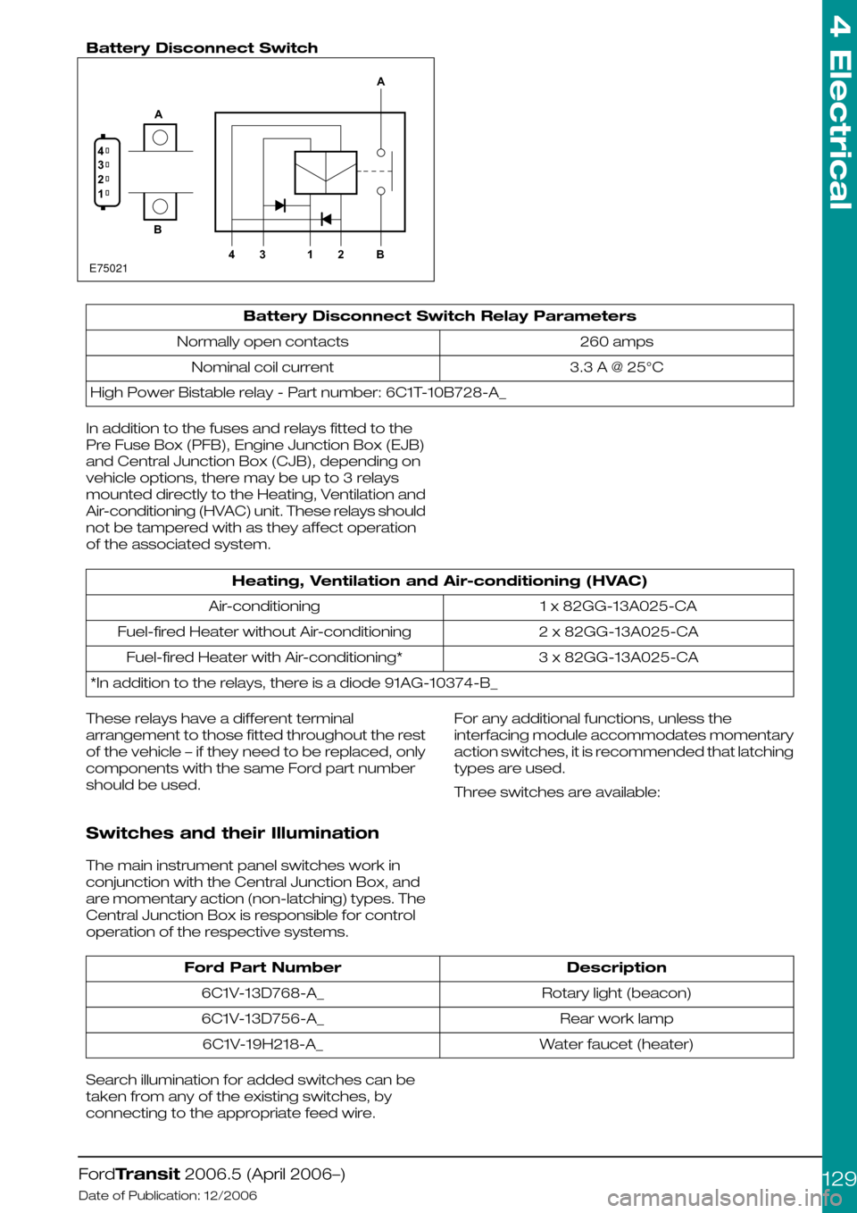
Battery Disconnect Switch
Battery Disconnect Switch Relay Parameters
260 ampsNormally open contacts
3.3 A @ 25°CNominal coil current
High Power Bistable relay - Part number: 6C1T-10B728-A_
In addition to the fuses and relays fitted to the
Pre Fuse Box (PFB), Engine Junction Box (EJB)
and Central Junction Box (CJB), depending on
vehicle options, there may be up to 3 relays
mounted directly to the Heating, Ventilation and
Air-conditioning (HVAC) unit. These relays should
not be tampered with as they affect operation
of the associated system.
Heating, Ventilation and Air-conditioning (HVAC)
1 x 82GG-13A025-CAAir-conditioning
2 x 82GG-13A025-CAFuel-fired Heater without Air-conditioning
3 x 82GG-13A025-CAFuel-fired Heater with Air-conditioning*
*In addition to the relays, there is a diode 91AG-10374-B_
These relays have a different terminal
arrangement to those fitted throughout the rest
of the vehicle – if they need to be replaced, only
components with the same Ford part number
should be used.
Switches and their Illumination
The main instrument panel switches work in
conjunction with the Central Junction Box, and
are momentary action (non-latching) types. The
Central Junction Box is responsible for control
operation of the respective systems.
For any additional functions, unless the
interfacing module accommodates momentary
action switches, it is recommended that latching
types are used.
Three switches are available:
DescriptionFord Part Number
Rotary light (beacon)6C1V-13D768-A_
Rear work lamp6C1V-13D756-A_
Water faucet (heater)6C1V-19H218-A_
Search illumination for added switches can be
taken from any of the existing switches, by
connecting to the appropriate feed wire.
FordTransit 2006.5 (April 2006–)
Date of Publication: 12/2006
4 Electrical
129E750211234AB4312BA
Page 162 of 234

How to change the 3 pre-set default
RPM values in the 3 speed mode
1.Enter ‘learn mode’ (see directions above)
2.Arm the RPM speed controller (turn the key
switch to ‘on’)
3.Press & release the brake pedal once
4.Press & release the RPM button that requires
re-programming
5.Use the accelerator pedal to rev the engine to
the new desired RPM speed & hold at this
speed (only speeds between 1200 to 3000
rpm can be selected in 3 speed mode)
6.Press & release the same RPM button to reset
the stored RPM speed to the current engines
RPM
7.Release the accelerator pedal
8.Repeat steps 4) to 7) for the remaining RPM
buttons
The 3 RPM speeds should now be
re-programmed to the new RPM speeds. The
new settings can be saved & learn mode exited
(see below)
NOTE: If the engine RPM responds to the initial
RPM button press, then the vehicle has not
entered ‘learn mode’ correctly & you will have to
restart the procedure. If the engine stalls out at
the brake or accelerator pedal inputs then the
vehicle was not in, or has dropped out of ‘learn
mode’ & you will have to restart the procedure.
How to save new settings & exit
from ‘Learn mode’
1.From within the ‘learn mode’ & with the RPM
Speed Control switch box ‘armed’, press the
clutch pedal repeatedly until the engine stalls.
2.Restart the engine & test the new settings,
repeat above procedures if necessary
NOTE: The engine stalling indicates that the
settings should have been saved & the vehicle
has exited from ‘learn mode’. Learn mode
however is very specific that the exact steps are
taken in the correct order & within certain time
limits otherwise the learn procedure fails & it may
take several attempts to get this order & timing
correct & a successful modification from the
default settings.
Some Reasons why RPM speed
Control operation may stop or fail
The RPM Speed control software monitors
vehicle information during operation in RPM
speed control mode & will drop out of RPM speed
control and / or stall the engine should any
adverse signals be detected. For example:
•If the engine temperature becomes too hot
then RPM speed control will stop in order to
protect the engine.
•If the engine oil light illuminates then RPM
speed control will stop in order to protect the
engine
•If the low fuel level light illuminates then RPM
speed control will stop so that the vehicle can
be driven to a refueling point.
•If the vehicle speed exceeds approx 2.5 mph
wile in 3 speed or variable speed modes, then
RPM speed control may stop. RPM speed
control should normally be operated with the
hand brake on, but some uses may require a
low level of vehicle ‘creep’ during RPM speed
control operation. Note that there is no sensing
of the park brake on this version of RPM speed
controller to facilitate this type of operation.
•The software monitors for ‘stuck on’ buttons
on the control switch box, this may result in
RPM speed control being halted. A button that
is held down for too long may be registered
by the software as a ‘stuck’ button.
•The software monitors the foot pedals, if
depressed these may stall the engine if in 3
speed mode or variable speed mode (does
not apply to idle up speed)
•If the control switch box circuitry significantly
exceeds 2110 ohms or there is a short circuit
then RPM speed control will not be possible.
•If a PTO conversion has been attempted on a
vehicle with a non ABS braking system then
RPM speed control will fail due to vehicle
speed being registered via a transmission
speed sensor and / or the need to press the
clutch in order to put the vehicle in gear while
in RPM speed control mode.
4.14.10 Adding Connectors,
Terminals and Wiring
Additional Rear Speakers
NOTE: The connectors on the Instrument Panel
harness (14K024) and the main harness (14401)
are reversed between Left Hand Drive (LHD) and
Right Hand Drive (RHD) vehicles, hence different
sets of terminals/wires are required to cover all
the markets.
FordTransit 2006.5 (April 2006–)
Date of Publication: 12/2006
4 Electrical
162