Page 129 of 234

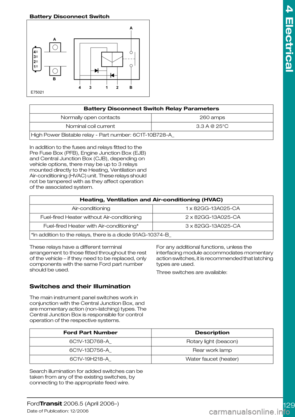
Battery Disconnect Switch
Battery Disconnect Switch Relay Parameters
260 ampsNormally open contacts
3.3 A @ 25°CNominal coil current
High Power Bistable relay - Part number: 6C1T-10B728-A_
In addition to the fuses and relays fitted to the
Pre Fuse Box (PFB), Engine Junction Box (EJB)
and Central Junction Box (CJB), depending on
vehicle options, there may be up to 3 relays
mounted directly to the Heating, Ventilation and
Air-conditioning (HVAC) unit. These relays should
not be tampered with as they affect operation
of the associated system.
Heating, Ventilation and Air-conditioning (HVAC)
1 x 82GG-13A025-CAAir-conditioning
2 x 82GG-13A025-CAFuel-fired Heater without Air-conditioning
3 x 82GG-13A025-CAFuel-fired Heater with Air-conditioning*
*In addition to the relays, there is a diode 91AG-10374-B_
These relays have a different terminal
arrangement to those fitted throughout the rest
of the vehicle – if they need to be replaced, only
components with the same Ford part number
should be used.
Switches and their Illumination
The main instrument panel switches work in
conjunction with the Central Junction Box, and
are momentary action (non-latching) types. The
Central Junction Box is responsible for control
operation of the respective systems.
For any additional functions, unless the
interfacing module accommodates momentary
action switches, it is recommended that latching
types are used.
Three switches are available:
DescriptionFord Part Number
Rotary light (beacon)6C1V-13D768-A_
Rear work lamp6C1V-13D756-A_
Water faucet (heater)6C1V-19H218-A_
Search illumination for added switches can be
taken from any of the existing switches, by
connecting to the appropriate feed wire.
FordTransit 2006.5 (April 2006–)
Date of Publication: 12/2006
4 Electrical
129E750211234AB4312BA
Page 130 of 234
4.13.7 Windscreen wipers
NOTE: Power to wiper motors is limited by the
size of the wiring and associated relays. If any
alternative wiper installation is made, it must have
a specification equivalent to Ford components.
Refer to: 5.6 Glass, Frames and Mechanisms
(page 211).
The base wiper system should not be tampered
with (controlled by Central Junction Box and
multiplex architecture).
Headlamp wash – such installations would need
to be controlled via an external timer relay. The
Special Vehicle Option Auxiliary Fuse Box should
be utilized.
Heated washer jets – aftermarket systems should
be fitted via an ignition feed, via an additional relay.
The Special Vehicle Option Auxiliary Fuse Box
should be utilized.
FordTransit 2006.5 (April 2006–)
Date of Publication: 12/2006
4 Electrical
130
Page 131 of 234

4.14 Special Conversions
4.14.1 Vehicle Speed Output
(Signal)
At present, this information is only readily available
as a CAN message. However, on Diesel vehicles
it is possible to access a hard-wired output.
In the engine compartment there are three
connectors on the left hand side (viewed from
driving direction). On left hand drive vehicles, the
three connectors are covered with a plastic
shield that can be easily disassembled. On right
hand drive vehicles there is a special metal
security shield fixed with a shear bolt (part
number 6M5Y-12B539-A*). The vehicle speed
signal is available on pin K1 of the middle (brown)
connector, C2 – see Figure E84720 (Additional
Vehicle Signal / Features). This provides a square
wave-form (50% duty cycle) signal, where a
frequency of 138Hz equates to 100km/h.
Note:-
•A hard-wired vehicle speed signal is only
available on diesel engine vehicles.
•Vehicle speed is derived from one of two
sources, the wheel speed sensor (for vehicles
with ABS etc.) or the vehicle speed signal – in
both cases, these are un-calibrated signals.
According to transmission, drive-line and other
vehicle parameters that are set, the
Powertrain Control Module generates a CAN
message of vehicle speed for all vehicle types.
There is No hard-wired vehicle speed signal
on gasoline (petrol) vehicles.
•There is No automated shift transmission for
V4347/8 (there are no plans to introduce this
later in the program).
•VMT6 transmissions will not support fitment
of a vehicle speed sensor.
Connector Position for Vehicle Speed Signal in the Engine Compartment
In order to avoid electrical issues due to leakage,
and to ensure connector compatibility, a
pre-crimped wire and terminal, available as part
of a wiring accessory kit, should be used (kit part
number KT6C1V-14A411-J*). For further
information see 'Adding Connectors, Terminals
and Wiring' in this manual.
FordTransit 2006.5 (April 2006–)
Date of Publication: 12/2006
4 Electrical
131E84714
Page 132 of 234

4.14.2 Engine Run Signal (D+ Alternative)
Give Away Engine-run Signal Connector (Passenger side)
WARNING: Do not cut into the
alternator wires or use the alternator
as a source to obtain a 'D+ Signal'
The Engine Run Signal will only support the basic
vehicle system.
Vehicles built from August 2006 will have a
suitable ‘give-away’ connector (6.3mm flat blade
receptacle) in the main vehicle harness. This is
located on the passenger side and can be
accessed by dropping the glove box.
Most early-build vehicles do not have this
connector. In such instances, for engine run (C4-7
on the central Junction Box), there is a dedicated
terminal (pin 16) on the passenger-door loom /
main loom in-line connector available to energize
a relay (maximum one (1) relay). A T-piece
harness (6C1V-14A411-F*) is available from your
Local Ford Dealer to fit between the door / main
loom in-line connector. If the vehicle does not
have this fitted as a factory-fitted option
(campers, for example, do have this pre-fitted),
one way to install this is:
•Remove the passenger side mirror on the
using a long-reach M8 socket (note: right hand
drive vehicles use shear bolts that will need to
be replaced)
•Pull out the flexible grommet between the
body and the door, including the connector
shroud behind it.
•The connector between the main vehicle
harness (14401) and the door jumper harness
(14A631) Can now be pulled through and
disconnected
•The T-piece jumper harness can be inserted
between the two connectors and pushed
back into the body.
•Drop the glove box fully by depressing the side
detents – the single lead with connector
(6.3mm male terminal) can be pulled through
a square hole in the body-side inner panel,
behind the flexible grommet
•Re-fitment of the flexible grommet and door
mirror is the reverse of the above process,
noting that new shear bolts will be necessary
for right hand drive vehicle, part number
W712939-S422.
This engine run signal is ground switching (max.
current sink 200mA), for example it provides no
positive output and is only active under the
following conditions:
•Ignition on
•Engine running at normal idle
•Alternator giving output
•System voltage about 9 volts
FordTransit 2006.5 (April 2006–)
Date of Publication: 12/2006
4 Electrical
132E84715
Page 133 of 234

The fitment of the Special Vehicle Option auxiliary
box will provide a power source for the relay
(although connection to the engine run pin is still
required).
Where connections are already made to the
engine run signal, it is vital that these connections
remain connected. In this instance, a suitable 'Y'
Jumper link should be used to tap out of the
connection.
Refer to: 4.13 Fuses and Relays (page 119).
If a positive (+12V) engine run signal is required,
this is possible by using the relay contacts to ‘pull
in’ 12V (preferably an ignition feed, KL15)
Ghost View of Engine Run Jumper Harness (only)
DescriptionItem
In-line to 14401 main loom1
In-line to 14A631 door loom2
Engine run output (6.3mm male connector), part of T-piece harness (6C1V-14A411-F*)3
4.14.3 Connectors
Cutting into the Original Wiring
System
WARNINGS:
Under no circumstances should the
CAN bus be tampered with. This
may lead to failure of safety critical
components such as Anti-lock
Brake System.
Do not use connectors which cut
through the outer covering and into
the core wire
CAUTION: Only use Ford approved
connectors
Cutting into vehicle wiring is not permitted
because:-
•The base vehicle specification is unsuitable
for incremental loads except in conjunction
with Special Vehicle Option Auxiliary Fuse Box.
•Long term risk of a faulty connection
developing.
•Potential fire risk from over-loading.
All connections into existing wiring must be
permanently insulated. Exterior connections must
be water-proof.
FordTransit 2006.5 (April 2006–)
Date of Publication: 12/2006
4 Electrical
133132E74851
Page 134 of 234

Where wires are required to be extended, break
in points should only be at existing connector
points and only Ford approved connectors should
be used.
Ford approved link harnesses should be used.
Unused Connectors
The harnesses may have a number of unused
connectors – these are dedicated to other
features and options, e.g. heated seats, but are
not always present depending on level of
harness fitted. Ford do not recommend the use
of these connectors for any other purpose than
that intended by design.
Power Outlet / Cigar Lighter
Both features adopt a 20A fusing strategy. With
a single battery system, continued loading of
these features will lead to battery drain, and risk
vehicle starting. If continuous power is required,
a second battery option should be installed and
the customer connection points, where fitted,
utilized.
4.14.4 Installation and Routing Guides
Anti-Lock Brake System Wiring Harness Routing
The installation and routing of Ford wiring
(including those provided as part of accessory
kits such as trailer tow) have been fully-validated
and have passed the requisite EMC tests. Ford
Motor Company; however, are not responsible
for the vehicle’s EMC immunity when
non-Ford-approved systems are installed.
WARNING: Do not route other wiring
near/close to electrical cables with
the Antilock Brake System and
Traction Control System cables
because of extraneous signal risk.
It is generally not recommended to
hang it off existing looms or pipes.
Wiring must be suitably fixed without any
detrimental effect on other wiring.
Single or bunched looms must maintain the
following clearances:
FordTransit 2006.5 (April 2006–)
Date of Publication: 12/2006
4 Electrical
134E79034
Page 135 of 234

•10mm from static components (unless
clamped to it).
•250mm from exhaust system.
•30mm from rotating or moving components.
Wires / looms passing through sheet metal must
be through protective grommets that also ensure
a watertight seal. Adhesive or tape is not
acceptable.
CAUTION: Do not feed additional
wires through existing ‘occupied’
grommets.
A number of locations in the dash panel have
been identified for additional holes to route wires
through. See figures E74496 Left Hand and
E74497 Right Hand Drive Dash Panels for
locations. The selection of suitable locations will
depend on the vehicle specification – please
check that the immediate surrounding area is
free from obstructions and/or components to
prevent damage to critical systems, and that the
grommet will seal properly.
Typically two sizes of hole are recommended:
•Grommet to suit with hole size 40mm
diameter for dash panel – bunched loom.
•Grommet to suit with hole size 30mm
diameter for dash panel – up to three (3)
wires.
Left Hand Drive Dash Panel
DescriptionItem
East/West Engine and Tachograph1
Available2
Global Site Management antenna3
Available4
Available5
WARNING: Holes must permit the
appropriate connector to pass
through.
FordTransit 2006.5 (April 2006–)
Date of Publication: 12/2006
4 Electrical
135E7449624513
Page 136 of 234

Right Hand Drive Dash Panel
DescriptionItem
East/West Engine and Tachograph1
Available2
Global Site Management antenna3
Available4
Available5
4.14.5 Electrics for Tow bar
Tow bar electrical system may be ordered as a
13-pin DIN connector, as part of the original
vehicle build.
Where it is required to add trailer towing to an
existing vehicle, and to ensure compliance with
lighting regulations, the appropriate wiring
accessory kit can be obtained from your Ford
Dealer. Fitment of non-Ford trailer tow wiring is
not advisable due to Central Junction Box control
of lighting, and meeting legal lighting regulations.
Contact your local Ford dealer for details of a
harness that connects to the base vehicle
harness. All Transits are provided with a basic
trailer tow interface - this connector is located on
the left hand side of the engine compartment
NOTE: For Van tow bars it is necessary to
connect into the rear lamp unit
For information, there is no trailer tell-tale in the
cluster, and if equipped with the Ford Trailer Tow
module, the vehicle’s rear fog lights are disabled
when a trailer is hitched-up.
A 7-pin trailer tow sub-harness is released by SVO
(part number 6C1V-13B576-A*); currently there
is no 7+7 sub-harness available, but figure E84722
is a proposal detailing the connectivity from the
in-line near the rear of the vehicle. The electrical
schematics for the 13-pin trailer tow system form
part of the workshop manual.
FordTransit 2006.5 (April 2006–)
Date of Publication: 12/2006
4 Electrical
136E7449724513