Page 81 of 234
3.4 Electronic Engine Controls
CAUTION: Do not make any
additional connections to the
electrical circuits associated with
the engine management system
NOTE: It is not necessary to disconnect or
remove engine management modules.
FordTransit 2006.5 (April 2006–)
Date of Publication: 12/2006
3 Powertrain
81
Page 82 of 234
3.5 Clutch
The manufacturer does not offer the option of a
reinforced clutch system. The axle ratio available
is dependent on the weight of the specified donor
vehicle.
It is necessary to select the appropriate drive,
engine, gear ratio, gross vehicle mass, gross train
mass, axle plates and payloads of the base
vehicle to match the customers order.
Where possible make sure that the base vehicle
is ordered with plant fit options
NOTE: For further information please contact
your local National Sales Company representative,
or Local Ford Dealer. If they are unable to help
you then please contact the Vehicle Converter
Advisory Service at [email protected].
FordTransit 2006.5 (April 2006–)
Date of Publication: 12/2006
3 Powertrain
82
Page 83 of 234
3.6 Manual Transmission
The following manual transmissions are available
for diesel engines dependent on the drive.
•Front Wheel Drive vehicles
–VXT 75 transmission
•Rear Wheel Drive vehicles
–MT 82 transmission or
–MT 75 transmission
The following manual transmission is available
for gasoline engines .
•Rear Wheel Drive vehicles
–MT 75 transmission
WARNING: Do not reroute external
transmission gear shift cables
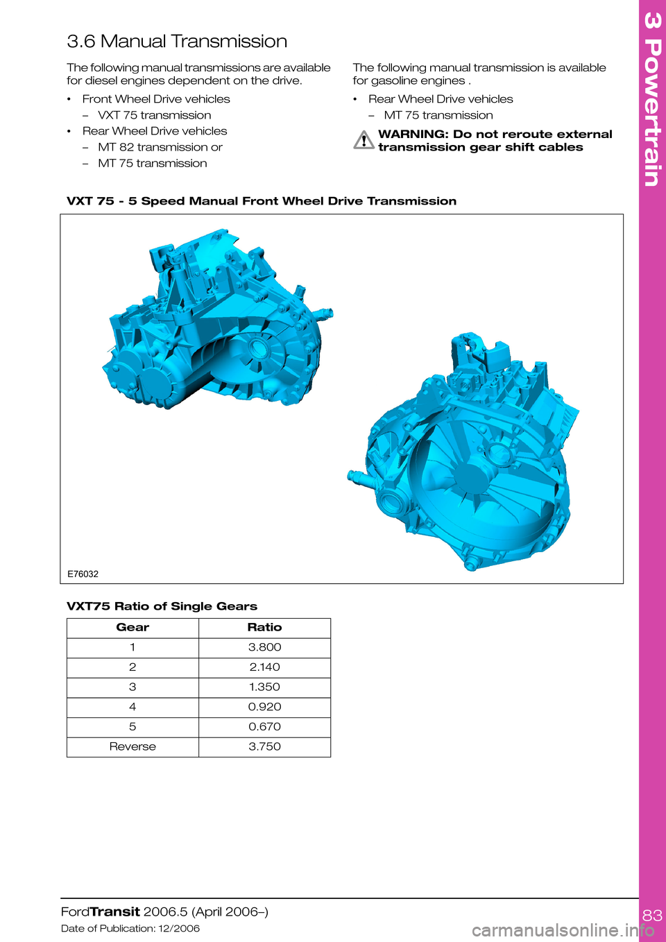
VXT 75 - 5 Speed Manual Front Wheel Drive Transmission
VXT75 Ratio of Single Gears
RatioGear
3.8001
2.1402
1.3503
0.9204
0.6705
3.750Reverse
FordTransit 2006.5 (April 2006–)
Date of Publication: 12/2006
3 Powertrain
83E76032
Page 84 of 234
MT82 - 6 Speed Manual Rear Wheel Drive Transmission
MT82 Ratio of Single Gears
RatioGear
5.4411
2.8392
1.7213
1.2234
1.0005
0.7946
3.750Reverse
FordTransit 2006.5 (April 2006–)
Date of Publication: 12/2006
3 Powertrain
84E76033
Page 85 of 234
MT75 - 5 Speed Manual Rear Wheel Drive Transmission
RatioGear
4.2001
2.2382
1.3663
1.0004
0.7635
3.600Reverse
FordTransit 2006.5 (April 2006–)
Date of Publication: 12/2006
3 Powertrain
85E76034
Page 86 of 234

3.7 Exhaust System
3.7.1 Extensions and Optional
Exhausts
CAUTIONS:
Non-standard systems must be
tested for engine back pressure and
all legal compliance (noise and
emissions)
Make sure that for any pipes that
require bending, the radius of the
bend is minimum 2.5x tube diameter
Make sure that sufficient clearance
is maintained for all driving
conditions to all hot and moving
components.
NOTE: Where possible all pipe connections
should be designed so that the gas flows from
smaller to larger diameter pipes
For some territories a side exhaust is available as
a Special Vehicle Option on Chassis Cab.
Exhaust Pipe Design Principles
DescriptionItem
diameterd
radius = 2.5dr
3.7.2 Exhaust Pipes and Supports
CAUTIONS:
Maintain the original set-up and heat
shields
Do not position any plastic, rubber
or any other components closer to
the down pipe, catalytic converter
that the original Ford design (100mm
minimum).
3.7.3 Exhaust Heat Shields
Low Floor Exhaust Heat Shields
•Catalytic converters, in particular, operate at
high temperatures
•Ensure existing shields are maintained
•Add further shields over exhaust system as
necessary to avoid fire risk.
FordTransit 2006.5 (April 2006–)
Date of Publication: 12/2006
3 Powertrain
86E74569rd
Page 87 of 234
Standard Exhaust Heat Shields
CAUTION: Standard heat shields are
available from your local dealer and
can easily be fitted. Additional heat
shields may be required over the
modified exhaust system,
particularly in areas of close
proximity to the floor.
NOTE: For further information please contact
your local National Sales Company
representative, or Local Ford Dealer. If they are
unable to help you then please contact the
Vehicle Converter Advisory Service at
[email protected].
FordTransit 2006.5 (April 2006–)
Date of Publication: 12/2006
3 Powertrain
87
Page 88 of 234

3.8 Fuel System
WARNINGS:
Do not cut into the original fuel
supply lines
Make sure that the modified vehicle
complies with all relevant legal
requirements.
For auxiliary applications requiring a fuel supply,
it is advisable to use the auxiliary fuel supply port
as shown in the figure below.
•The auxiliary fuel supply port is mounted on
the top of the fuel sender unit located on the
top of the fuel tank, for applications such as
an auxiliary heater or fuel fired hand wash
facility.
•Ensure that a suitable fuel shut-off is fitted in
any unique system.
•Refit the Ford hose assembly from the fuel
pump to the fuel line.
•The tube and/or line must be routed
independently and secured to the body
structure or to suitable brackets.
CAUTION: Make sure that sufficient
clearance is maintained for all
driving conditions to all hot and
moving components.
NOTE: Do not fasten anything to existing
electrical components or wires
FordTransit 2006.5 (April 2006–)
Date of Publication: 12/2006
3 Powertrain
88