Page 2523 of 5267

MANUAL TRANSMISSION - G56 - SERVICE INFORMATION
DIAGNOSIS AND TESTING
MANUAL TRANSMISSION - G56
LOW LUBRICANT LEVEL
A low transmission lubricant level is generally the result of a leak, inadequate lubricant fill or incorrect lubricant level
check.
Rear transmission leakswill be from the oil seals or component mating surfaces.
Front transmission leakswill be from the front input shaft retainer seal. Lubricant may drip from theclutchhousing
after extended operation. If leak is severe, it may contaminate the clutchdisc.
Lubricant level checkcan only be made when the vehicle is level and allowing the lubricant to settle for a minute
before checking. This will ensure an accurate check and avoid an under or overfill condition.
HARD SHIFTING
Hard shifting is usually caused by low lubricant level, improper or contaminated lubricants. This will cause noise,
excessive wear, internal bind, and hard shifting. Substantial lubricantleaks can result in gear, shift rail, synchro, and
bearing damage. The first indications of component damage is usually hardshifting and noise.
Shift component damage, clutch adjustment, worn pressure plate or disc are also causes of increased shift effort. If
clutch problem is advanced, gear clash during shifts can result. Worn or damaged synchronizer rings can cause
gear clash when shifting into any forward gear. In some new or rebuilt transmissions, new synchro rings may tend
to stick slightly causing hard or noisy shifts. In most cases, this condition will decline as the rings wear-in.
TRANSMISSION NOISE
Most manual transmissions make some noise during normal operation. Rotating gears generate a mild whine that is
audible, but generally only at extreme speeds.
Severe, highly audible transmission noise is generally the initial indicator of a lubricant problem. Insufficient,
improper or contaminated lubricant will promote rapid wear of gears, synchronizer rings, shift rails, forks and bear-
ings. The overheating caused by a lubricant problem, can also lead to gear and bearing damage.
Page 2544 of 5267
COUNTERSHAFT
NOTE: Bearings are the only component serviced
on the countershaft.
1. Remove countershaft rear housing bearing with
Puller 6444 (1), Plug 8513A (2), Puller Jaws 9597
(3) , Puller Collar 6444-8 (4), Puller Rods 6444-3
and Puller Flange 6444-1. Position Puller Jaws
9597 around bearing and puller flange. Position
puller collar around the puller jaws. Tighten the
puller bolt and remove countershaft bearing.
2. Remove countershaft first/reverse gear bearing oil
slinger from countershaft.
3. Remove countershaft front housing bearing with
Puller 6444 (1), Puller Collar 6444-8 (2), Puller
Jaws 9597 (3), Puller Rods 6444-3 and Puller
Flange 6444-1. Position puller jaws around bearing
and puller flange. Position puller collar around the
puller jaws. Tighten the puller bolt and remove
countershaft bearing.
Page 2548 of 5267
2. Install Remover 8915 (1) on puller (2) and tighten
remover nut (3) to pull cups out of the housing.
Then remove end-play shims from bearing bores
and oil supply washer from mainshaft bearing bore.
3. Remove input shaft retainer (1) bolts (2) and
remove retainer.
4. Remove input shaft seal (1) from retainer bore (2)
with a seal pick.
Page 2549 of 5267

CLEANING
Clean gears, shafts, shift components and transmission housings with a standard parts cleaning solvent. Do not use
acid or corrosive base solvents. Dry all parts except bearings with compressed air.
Clean shaft bearings with a mild solvent such as MOPAR
degreasing solvent, Gunkor similar solvents. Do not
dry the bearings with compressed air. Allow the bearings to either air dry or wipe them dry with clean shop towels.
INSPECTION
NOTE: Minor corrosion, nicks, or pitting can be
smoothed with 400 grit emery and polished out
with crocus cloth.
Bearings:Inspect for worn, chipped, cracked, flat-
spotted or brinnelled.
Gears:Inspect for worn, chipped or cracked teeth.
Inspect bearing surfaces for wear or flat-spotted.
Mainshaft:Inspect for worn splines, snap ring
grooves and threads.
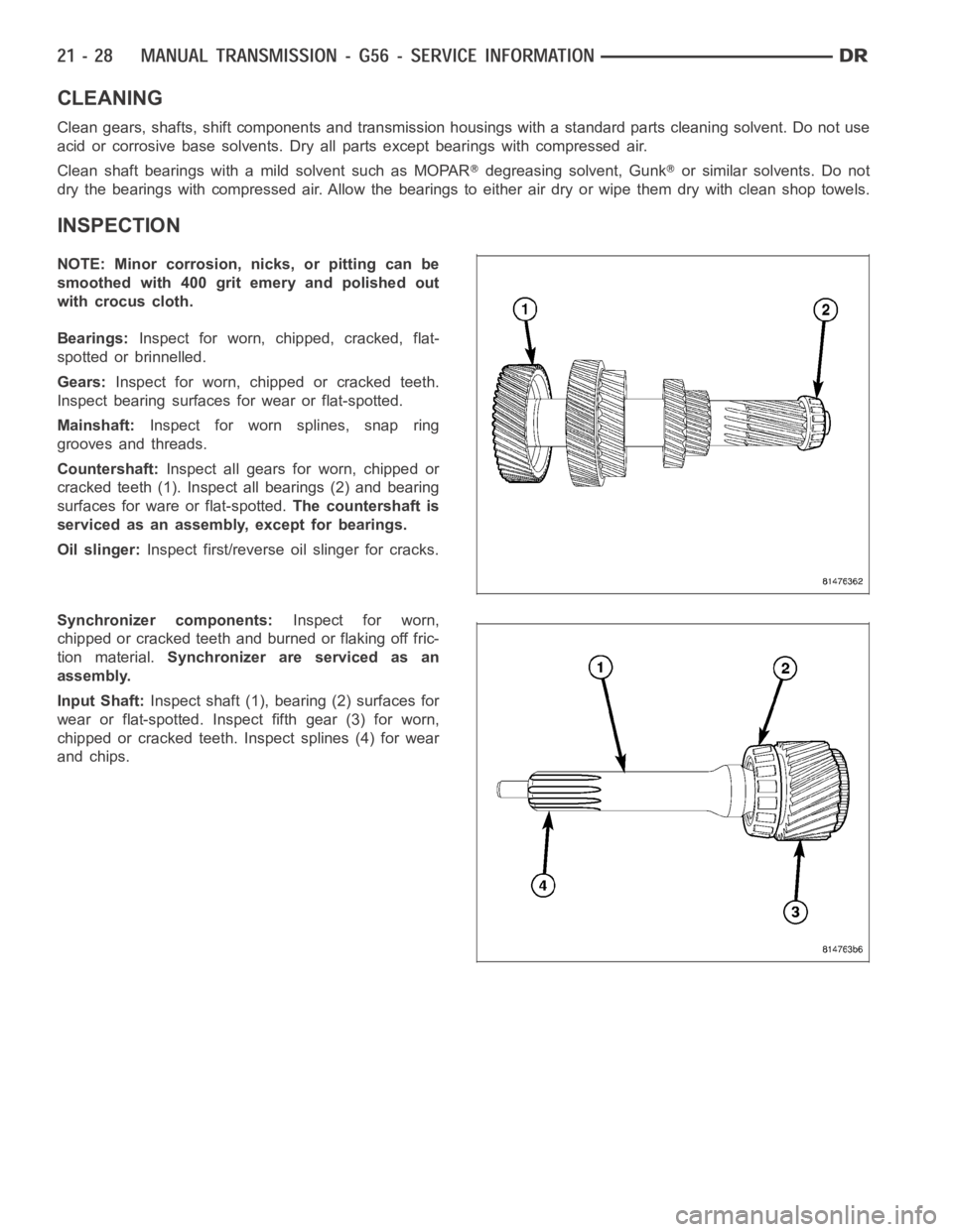
Countershaft:Inspect all gears for worn, chipped or
cracked teeth (1). Inspect all bearings (2) and bearing
surfaces for ware or flat-spotted.The countershaft is
serviced as an assembly, except for bearings.
Oil slinger:Inspect first/reverse oil slinger for cracks.
Synchronizer components:Inspect for worn,
chipped or cracked teeth and burned or flaking off fric-
tion material.Synchronizer are serviced as an
assembly.
Input Shaft:Inspect shaft (1), bearing (2) surfaces for
wear or flat-spotted. Inspect fifth gear (3) for worn,
chipped or cracked teeth. Inspect splines (4) for wear
and chips.
Page 2552 of 5267
3. Push input shaft mainshaft bearing seal (1) on the
end of fifth gear (2).
COUNTERSHAFT
1. Install first/reverse gear bearing oil slinger on the
rear housing end of the countershaft.
2. Heat rear housing countershaft bearing (1) on
bearing heater (2) to a maximum of 177 Celsius
(350° Fahrenheit).
Page 2574 of 5267
7. Install reverse (1), 1-2 (2) and 3-4 (3) shift rails and
forks as and assembly on synchronizer sleeves.
8. Install mainshaft with shift rails (2) into the rear
housing. Tilt the mainshaft then tilt the countershaft
(1) into the housing.
9. Position first/reverse oil slinger (1) between the
mainshaft first (2) and reverse gears, then
straighten the shafts in the housing.
CAUTION: Oil slinger is fragile and can crack dur-
ing installation. Failure to follow these instructions
will result in cracking the oil slinger and lack of oil
to first/reverse bearing.
Page 2577 of 5267
2. Install input shaft retainer (1) and tighten bolts (2)
to 23 Nꞏm (17 ft. lbs.).
3. Install select end play shims into the countershaft
bearing cup bore.
4. Install countershaft bearing cup with Installer 9589
(1) and Handle C-4171 (2).
5. Install input shaft bearing oil supply washer and
select end play shims into mainshaft bearing cup
bore.
6. Install mainshaft bearing cup with Installer 9588 (1)
and Handle C-4171 (2).
Page 2583 of 5267

19. Remove fill plug (1) on transmission (2) and fill to
bottom edge of fill plug hole.
20. Install fill plug and tighten to 57 Nꞏm (42 ft. lbs.).
21. Connect battery negative cable.
22. Install shift lever extension on shift tower and
lever assembly.
23. Slide boot down on shift lever extension and
install shift boot bezel and screws.
24. Install skid plate, if equipped.
ADJUSTMENTS
MAINSHAFT/COUNTERSHAFT BEARING PRELOAD
CAUTION: This procedure must be performed any time a mainshaft, countershaft or input shaft bearing or
shaft is replaced. Failure to follow these instructions will result in damaging the transmission.
MAINSHAFT
1. Set mainshaft, input shaft and countershaft into the
rear housing. Rotate the shafts to seat bearing in
rear housing.
2. Remove mainshaft bearing cup, shims and oiler
washer from the front housing.
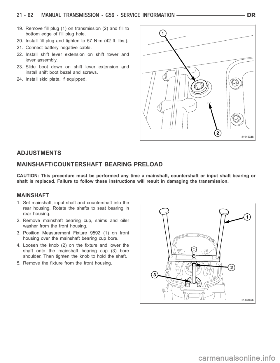
3. Position Measurement Fixture 9592 (1) on front
housing over the mainshaft bearing cup bore.
4. Loosen the knob (2) on the fixture and lower the
shaft onto the mainshaft bearing cup (3) bore
shoulder. Then tighten the knob to hold the shaft.
5. Remove the fixture from the front housing.