2006 DODGE RAM SRT-10 oil
[x] Cancel search: oilPage 2481 of 5267
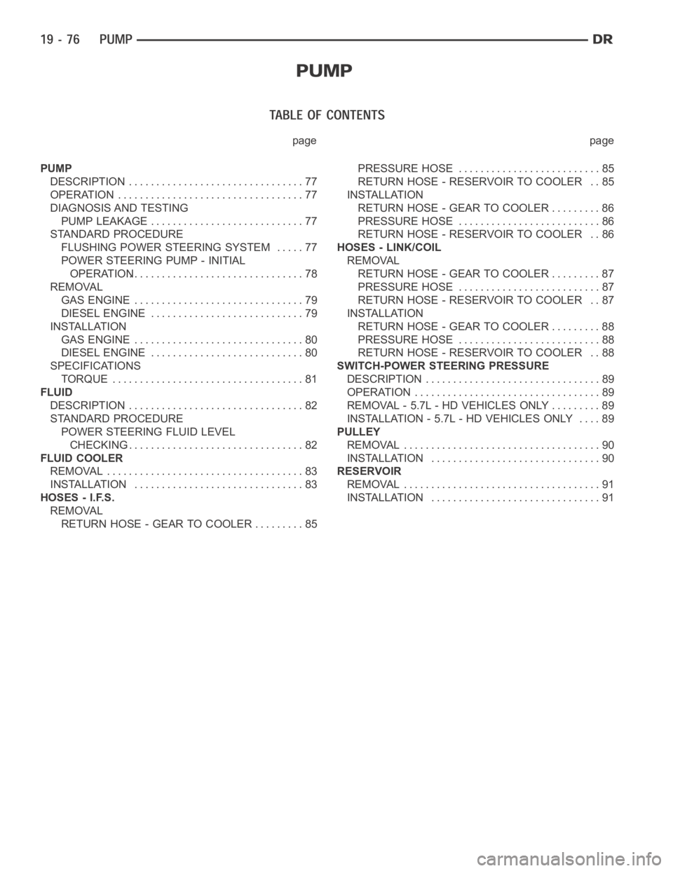
page page
PUMP
DESCRIPTION ................................ 77
OPERATION .................................. 77
DIAGNOSIS AND TESTING
PUMP LEAKAGE ............................ 77
STANDARD PROCEDURE
FLUSHING POWER STEERING SYSTEM . . . . . 77
POWER STEERING PUMP - INITIAL
OPERATION................................ 78
REMOVAL
GAS ENGINE ............................... 79
DIESEL ENGINE............................ 79
INSTALLATION
GAS ENGINE ............................... 80
DIESEL ENGINE............................ 80
SPECIFICATIONS
TORQUE ................................... 81
FLUID
DESCRIPTION ................................ 82
STANDARD PROCEDURE
POWER STEERING FLUID LEVEL
CHECKING................................. 82
FLUID COOLER
REMOVAL .................................... 83
INSTALLATION ............................... 83
HOSES - I.F.S.
REMOVAL
RETURN HOSE - GEAR TO COOLER ......... 85PRESSURE HOSE .......................... 85
RETURN HOSE - RESERVOIR TO COOLER . . 85
INSTALLATION
RETURN HOSE - GEAR TO COOLER ......... 86
PRESSURE HOSE .......................... 86
RETURN HOSE - RESERVOIR TO COOLER . . 86
HOSES - LINK/COIL
REMOVAL
RETURN HOSE - GEAR TO COOLER ......... 87
PRESSURE HOSE .......................... 87
RETURN HOSE - RESERVOIR TO COOLER . . 87
INSTALLATION
RETURN HOSE - GEAR TO COOLER ......... 88
PRESSURE HOSE .......................... 88
RETURN HOSE - RESERVOIR TO COOLER . . 88
SWITCH-POWER STEERING PRESSURE
DESCRIPTION ................................ 89
OPERATION .................................. 89
REMOVAL - 5.7L - HD VEHICLES ONLY ......... 89
INSTALLATION - 5.7L - HD VEHICLES ONLY .... 89
PULLEY
REMOVAL .................................... 90
INSTALLATION ............................... 90
RESERVOIR
REMOVAL .................................... 91
INSTALLATION ............................... 91
Page 2483 of 5267
1. Raise the front end of the vehicle off the ground until the wheels are freeto turn.
2. Remove the return line from the pump.
NOTE: If vehicle is equipped with a hydraulic booster remove both return lines from the pump.
3. Plug the return line port/ports at the pump.
4. Position the return line/lines into a large container to catch the fluid.
5. While an assistant is filling the pump reservoir start the engine.
6. With the engine running at idle turn the wheel back and forth.
NOTE: Do not contact or hold the wheel against the steering stops.
7. Run a quart of fluid through the system then stop the engine and install the return line/lines.
8. Fill the system with fluid and perform Steering Pump Initial Operation,(Refer to 19 - STEERING/PUMP - STAN-
DARD PROCEDURE).
9. Start the engine and run it for fifteen minutes then stop the engine.
10. Remove the return line/lines from the pump and plug the pump port/ports.
11. Pour fresh fluid into the reservoir and check the draining fluid for contamination. If the fluid is still contaminated,
then flush the system again.
12. Install the return line/lines and perform Steering Pump Initial Operation, (Refer to 19 - STEERING/PUMP -
STANDARD PROCEDURE).
POWER STEERING PUMP - INITIAL OPERATION
WARNING: THE FLUID LEVEL SHOULD BE CHECKED WITH ENGINE OFF TO PREVENT INJURYFROMMOV-
ING COMPONENTS.
CAUTION: MOPAR
ATF+4 is to be used in the power steering system. No other power steering or auto-
matic transmission fluid is to be used in the system. Damage may result to the power steering pump and
system if any other fluid is used, and do not overfill.
Wipe filler cap clean, then check the fluid level. The dipstick should indicateCOLDwhen the fluid is at normal
temperature.
1. Turn steering wheel all the way to the left.
2. Fill reservoir up to FULL HOT level and crank engine until it just starts.(DO NOT TURN STEERING WHEEL).
Then turn vehicle off. And recheck fluid level, to Full COLD.
3. Crank engine again until it just starts, (DO NOT MOVE STEERING WHEEL). and turn vehicle off. Recheck fluid
leveltoFullCOLD.
4. Turn engine on again, (DO NOT MOVE STEERING WHEEL) and let the vehicle idle for 5 minutes. If possible
apply a 20 in-Hg vacuum to the reservoir, while engine is idling.
5. Turn engine off and recheck fluid level, to FULL COLD.
6.If the Steering gear is replacedensure reservoir is at FULL HOT level, start engine and turn wheel to left. Stop
Engine and recheck fluid level to FULL HOT. Start engine and turn wheel to the right. Stop engine and check
fluid level is at FULL COLD.
7. Fill the pump fluid reservoir to the proper level and let the fluid settlefor at least two (2) minutes.
8. Start the engine. With the engine idling maintain the fluid level.
9. Raise the front wheels off the ground.
10. Slowly turn the steering wheel lock-to-lock 20 times with the engine off while checking the fluid level.
NOTE: For vehicles with long return lines or oil coolers turn wheel 40 times.
11. Lower the front wheels and let the engine idle for two minutes.
12. Turn the steering wheel in both direction and verify power assist and quiet operation of the pump.
If the fluid is extremely foamy or milky looking, allow the vehicle to standa few minutes and repeat the procedure.
Page 2487 of 5267
FLUID
DESCRIPTION
NOTE: It is normal that some pressure will build up inside the reservoir, especially, with a warm vehicle. A
slight popping noise upon removal ofthe cap is normal. The fluid level should read between the ADD and
the FULL COLD marks. When the fluid is hotit should read between ADD and FULLHOT marks. Only add
fluid when the vehicle is cold.
The recommended fluid for the power steering system is Mopar
AT F + 4 .
Mopar
ATF+4, when new is red in color. The ATF+4 is dyed red so it can be identified from other fluids used in the
vehicle such as engine oil or antifreeze. The red color is not permanent andis not an indicator of fluid condition, As
the vehicle is driven, the ATF+4 will begin to look darker in color and may eventually become brown.THIS IS NOR-
MAL.ATF+4 also has a unique odor that may change with age. Consequently, odor and color cannot be used to
indicate the fluid condition or the need for a fluid change.
STANDARD PROCEDURE
POWER STEERING FLUID LEVEL CHECKING
WARNING: FLUID LEVEL SHOULD BE CHECKED WITH THE ENGINE OFF TO PREVENT PERSONAL INJURY
FROM MOVING PARTS.
CAUTION: MOPAR
ATF+4 is to be used in the power steering system. No other power steering or auto-
matic transmission fluid is to be used in the system. Damage may result to the power steering pump and
system if any other fluid is used, and do not overfill.
The power steering fluid level can be viewed on the dipstick attached to thefiller cap. There are two ranges listed
on the dipstick, COLD and HOT. Before opening power steering system, wipe the reservoir filler cap free of dirt and
debris. Remove the cap and check the fluid level on its dipstick. When the fluid is at normal ambient temperature,
approximately 21°C to 27°C (70°F to 80°F), the fluid level should read between the minimum and maximum area of
the cold range. When the fluid is hot, fluid level is allowed to read up to thehighest end of the HOT range. Only add
fluid when the vehicle is cold.
Use only Mopar
AT F + 4 .Do not overfill the power steering system.
Page 2492 of 5267
HOSES - LINK/COIL
REMOVAL
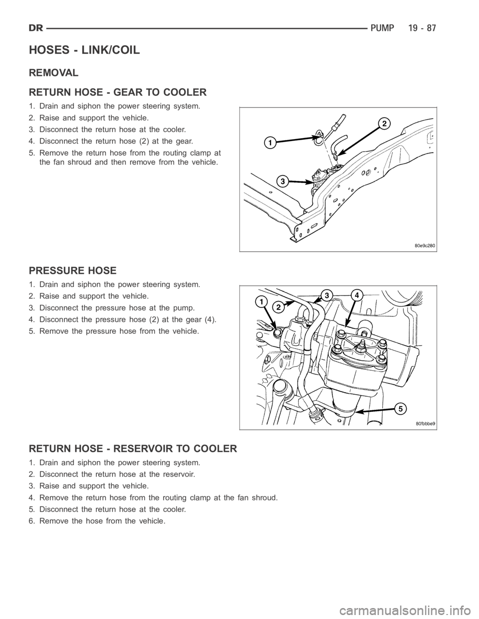
RETURN HOSE - GEAR TO COOLER
1. Drain and siphon the power steering system.
2. Raise and support the vehicle.
3. Disconnect the return hose at the cooler.
4. Disconnect the return hose (2) at the gear.
5. Remove the return hose from the routing clamp at
the fan shroud and then remove from the vehicle.
PRESSURE HOSE
1. Drain and siphon the power steering system.
2. Raise and support the vehicle.
3. Disconnect the pressure hose at the pump.
4. Disconnect the pressure hose (2) at the gear (4).
5. Remove the pressure hose from the vehicle.
RETURN HOSE - RESERVOIR TO COOLER
1. Drain and siphon the power steering system.
2. Disconnect the return hose at the reservoir.
3. Raise and support the vehicle.
4. Remove the return hose from the routing clamp at the fan shroud.
5. Disconnect the return hose at the cooler.
6. Remove the hose from the vehicle.
Page 2501 of 5267
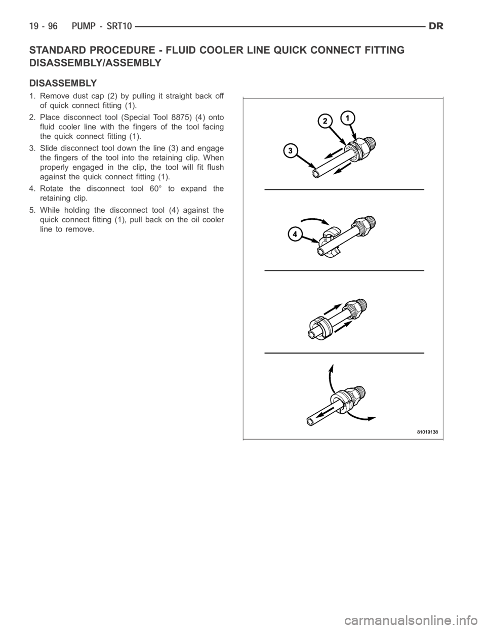
STANDARD PROCEDURE - FLUID COOLER LINE QUICK CONNECT FITTING
DISASSEMBLY/ASSEMBLY
DISASSEMBLY
1. Remove dust cap (2) by pulling it straight back off
of quick connect fitting (1).
2. Place disconnect tool (Special Tool 8875) (4) onto
fluid cooler line with the fingers of the tool facing
the quick connect fitting (1).
3. Slide disconnect tool down the line (3) and engage
the fingers of the tool into the retaining clip. When
properly engaged in the clip, the tool will fit flush
against the quick connect fitting (1).
4. Rotate the disconnect tool 60° to expand the
retaining clip.
5. While holding the disconnect tool (4) against the
quick connect fitting (1), pull back on the oil cooler
line to remove.
Page 2502 of 5267
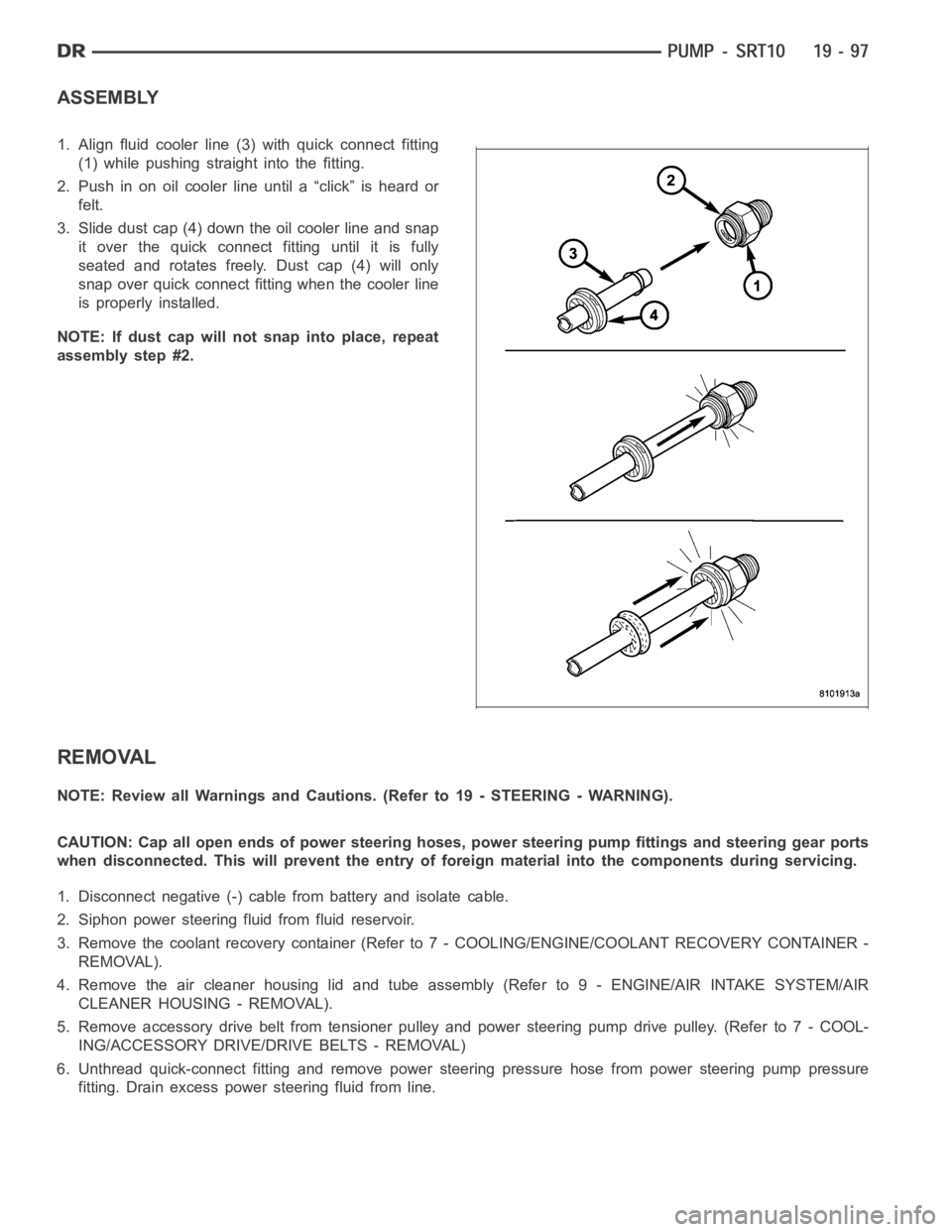
ASSEMBLY
1. Align fluid cooler line (3) with quick connect fitting
(1) while pushing straight into the fitting.
2. Push in on oil cooler line until a “click” is heard or
felt.
3. Slide dust cap (4) down the oil cooler line and snap
it over the quick connect fitting until it is fully
seated and rotates freely. Dust cap (4) will only
snap over quick connect fitting when the cooler line
is properly installed.
NOTE: If dust cap will not snap into place, repeat
assembly step #2.
REMOVAL
NOTE: Review all Warnings and Cautions. (Refer to 19 - STEERING - WARNING).
CAUTION: Cap all open ends of power steering hoses, power steering pump fittings and steering gear ports
when disconnected. This will prevent the entry of foreign material into the components during servicing.
1. Disconnect negative (-) cable from battery and isolate cable.
2. Siphon power steering fluid from fluid reservoir.
3. Remove the coolant recovery container (Refer to 7 - COOLING/ENGINE/COOLANT RECOVERY CONTAINER -
REMOVAL).
4. Remove the air cleaner housing lid and tube assembly (Refer to 9 - ENGINE/AIR INTAKE SYSTEM/AIR
CLEANER HOUSING - REMOVAL).
5. Remove accessory drive belt from tensioner pulley and power steering pump drive pulley. (Refer to 7 - COOL-
ING/ACCESSORY DRIVE/DRIVE BELTS - REMOVAL)
6. Unthread quick-connect fitting and remove power steering pressure hose from power steering pump pressure
fitting. Drain excess power steering fluid from line.
Page 2503 of 5267
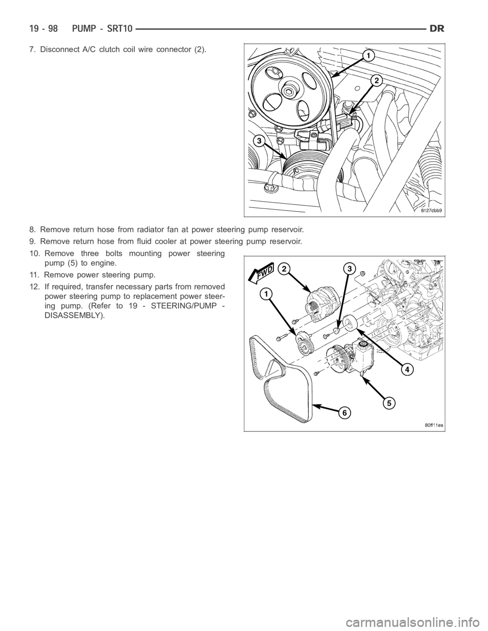
7. Disconnect A/C clutch coil wire connector (2).
8. Remove return hose from radiator fan at power steering pump reservoir.
9. Remove return hose from fluid cooler at power steering pump reservoir.
10. Remove three bolts mounting power steering
pump (5) to engine.
11. Remove power steering pump.
12. If required, transfer necessary parts from removed
power steering pump to replacement power steer-
ing pump. (Refer to 19 - STEERING/PUMP -
DISASSEMBLY).
Page 2504 of 5267
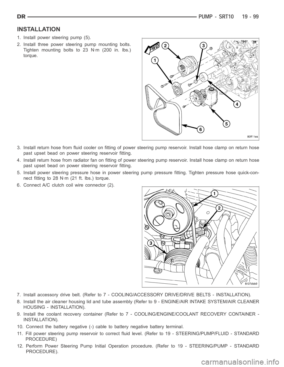
INSTALLATION
1. Install power steering pump (5).
2. Install three power steering pump mounting bolts.
Tighten mounting bolts to 23 Nꞏm (200 in. lbs.)
torque.
3. Install return hose from fluid cooler on fitting of power steering pump reservoir. Install hose clamp on return hose
past upset bead on power steering reservoir fitting.
4. Install return hose from radiator fan on fitting of power steering pump reservoir. Install hose clamp on return hose
past upset bead on power steering reservoir fitting.
5. Install power steering pressure hose in power steering pump pressure fitting. Tighten pressure hose quick-con-
nect fitting to 28 Nꞏm (21 ft. lbs.) torque.
6. Connect A/C clutch coil wire connector (2).
7. Install accessory drive belt. (Refer to 7 - COOLING/ACCESSORY DRIVE/DRIVE BELTS - INSTALLATION).
8. Install the air cleaner housing lid and tube assembly (Refer to 9 - ENGINE/AIR INTAKE SYSTEM/AIR CLEANER
HOUSING - INSTALLATION).
9. Install the coolant recovery container (Refer to 7 - COOLING/ENGINE/COOLANT RECOVERY CONTAINER -
INSTALLATION).
10. Connect the battery negative (-) cable to battery negative battery terminal.
11. Fill power steering pump reservoir to correct fluid level. (Refer to 19- STEERING/PUMP/FLUID - STANDARD
PROCEDURE)
12. Perform Power Steering Pump Initial Operation procedure. (Refer to 19- STEERING/PUMP - STANDARD
PROCEDURE).