Page 2357 of 5267
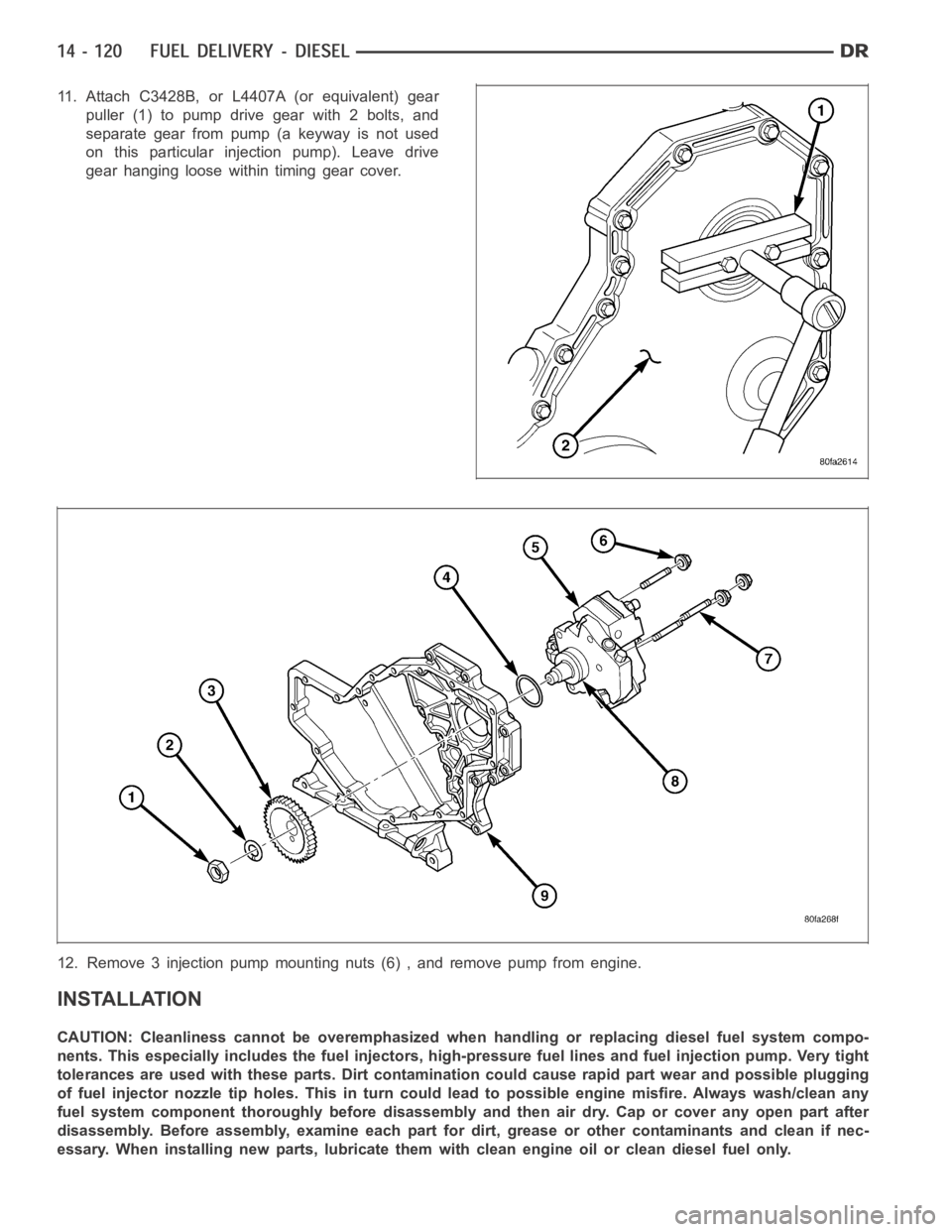
11. Attach C3428B, or L4407A (or equivalent) gear
puller (1) to pump drive gear with 2 bolts, and
separate gear from pump (a keyway is not used
on this particular injection pump). Leave drive
gear hanging loose within timing gear cover.
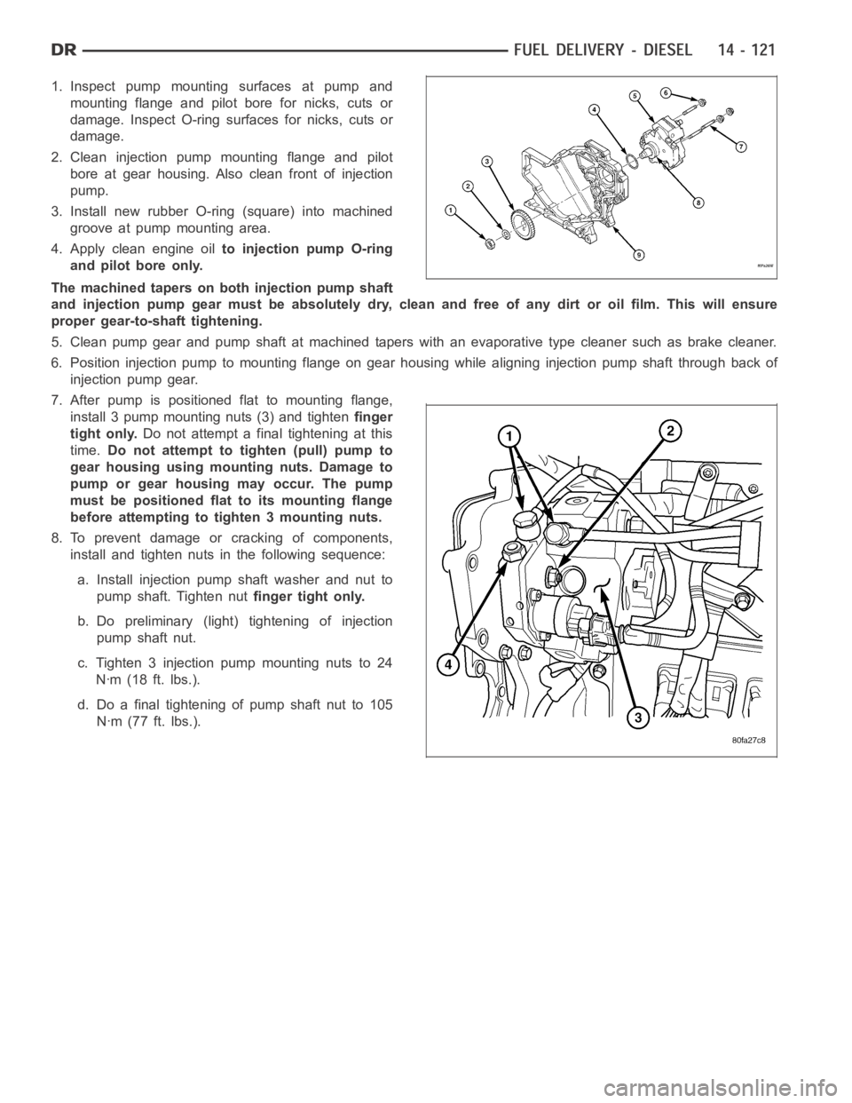
12. Remove 3 injection pump mounting nuts (6) , and remove pump from engine.
INSTALLATION
CAUTION: Cleanliness cannot be overemphasized when handling or replacingdieselfuelsystemcompo-
nents. This especially includes the fuel injectors, high-pressure fuel lines and fuel injection pump. Very tight
tolerances are used with these parts. Dirt contamination could cause rapid part wear and possible plugging
of fuel injector nozzle tip holes. This in turn could lead to possible engine misfire. Always wash/clean any
fuel system component thoroughly before disassembly and then air dry. Capor cover any open part after
disassembly. Before assembly, examine each part for dirt, grease or othercontaminants and clean if nec-
essary. When installing new parts, lubricate them with clean engine oil orclean diesel fuel only.
Page 2358 of 5267
1. Inspect pump mounting surfaces at pump and
mounting flange and pilot bore for nicks, cuts or
damage. Inspect O-ring surfaces for nicks, cuts or
damage.
2. Clean injection pump mounting flange and pilot
bore at gear housing. Also clean front of injection
pump.
3. Install new rubber O-ring (square) into machined
groove at pump mounting area.
4. Apply clean engine oilto injection pump O-ring
and pilot bore only.
The machined tapers on both injection pump shaft
and injection pump gear must be absolutely dry, clean and free of any dirt oroil film. This will ensure
proper gear-to-shaft tightening.
5. Clean pump gear and pump shaft at machined tapers with an evaporative type cleaner such as brake cleaner.
6. Position injection pump to mounting flange on gear housing while aligning injection pump shaft through back of
injection pump gear.
7. After pump is positioned flat to mounting flange,
install 3 pump mounting nuts (3) and tightenfinger
tight only.Do not attempt a final tightening at this
time.Do not attempt to tighten (pull) pump to
gear housing using mounting nuts. Damage to
pump or gear housing may occur. The pump
must be positioned flat to its mounting flange
before attempting to tighten 3 mounting nuts.
8. To prevent damage or cracking of components,
install and tighten nuts in the following sequence:
a. Install injection pump shaft washer and nut to
pump shaft. Tighten nutfinger tight only.
b. Do preliminary (light) tightening of injection
pump shaft nut.
c. Tighten 3 injection pump mounting nuts to 24
Nꞏm (18 ft. lbs.).
d. Do a final tightening of pump shaft nut to 105
Nꞏm (77 ft. lbs.).
Page 2360 of 5267
13. Connect Fuel Control Actuator (FCA) electrical
connector (3) to rear of injection pump.
14. Install intake manifold air intake tube (above injec-
tion pump). Tighten clamps.
15. Install accessory drive belt.
16. Connect both negative battery cables to both bat-
teries.
17. Check system for fuel or engine oil leaks.
Page 2363 of 5267
REMOVAL
CAUTION: Cleanliness cannot be overemphasized when handling or replacingdieselfuelsystemcompo-
nents. This especially includes the fuel injectors, high-pressure fuel lines and fuel injection pump. Very tight
tolerances are used with these parts. Dirt contamination could cause rapid part wear and possible plugging
of fuel injector nozzle tip holes. This in turn could lead to possible engine misfire. Always wash/clean any
fuel system component thoroughly before disassembly and then air dry. Capor cover any open part after
disassembly. Before assembly, examine each part for dirt, grease or othercontaminants and clean if nec-
essary. When installing new parts, lubricate them with clean engine oil orclean diesel fuel only.
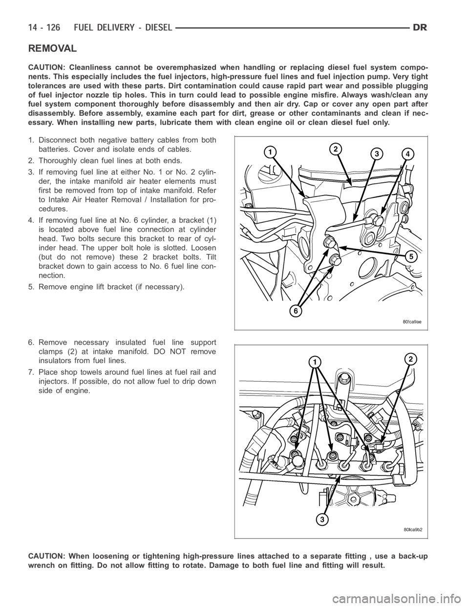
1. Disconnect both negative battery cables from both
batteries. Cover and isolate ends of cables.
2. Thoroughly clean fuel lines at both ends.
3. If removing fuel line at either No. 1 or No. 2 cylin-
der, the intake manifold air heater elements must
first be removed from top of intake manifold. Refer
to Intake Air Heater Removal / Installation for pro-
cedures.
4. If removing fuel line at No. 6 cylinder, a bracket (1)
is located above fuel line connection at cylinder
head. Two bolts secure this bracket to rear of cyl-
inder head. The upper bolt hole is slotted. Loosen
(but do not remove) these 2 bracket bolts. Tilt
bracket down to gain access to No. 6 fuel line con-
nection.
5. Remove engine lift bracket (if necessary).
6. Remove necessary insulated fuel line support
clamps (2) at intake manifold. DO NOT remove
insulators from fuel lines.
7. Place shop towels around fuel lines at fuel rail and
injectors. If possible, do not allow fuel to drip down
side of engine.
CAUTION: When loosening or tightening high-pressure lines attached to a separate fitting , use a back-up
wrench on fitting. Do not allow fitting to rotate. Damage to both fuel line and fitting will result.
Page 2367 of 5267
VALVE - FUEL PRESSURE LIMITING
DESCRIPTION
The fuel pressure limiting valve is located on the top of the fuel rail.
OPERATION
Fuel pressure at the fuel rail is monitored by the fuel rail pressure sensor. If fuel pressure becomes excessive, the
pressure limiting valve opens and vents excess pressure into the fuel draincircuit.
REMOVAL
CAUTION: Cleanliness cannot be overemphasized when handling or replacingdieselfuelsystemcompo-
nents. This especially includes the fuel injectors, high-pressure fuel lines and fuel injection pump. Very tight
tolerances are used with these parts. Dirt contamination could cause rapid part wear and possible plugging
of fuel injector nozzle tip holes. This in turn could lead to possible engine misfire. Always wash/clean any
fuel system component thoroughly before disassembly and then air dry. Capor cover any open part after
disassembly. Before assembly, examine each part for dirt, grease or othercontaminants and clean if nec-
essary. When installing new parts, lubricate them with clean engine oil orclean diesel fuel only.
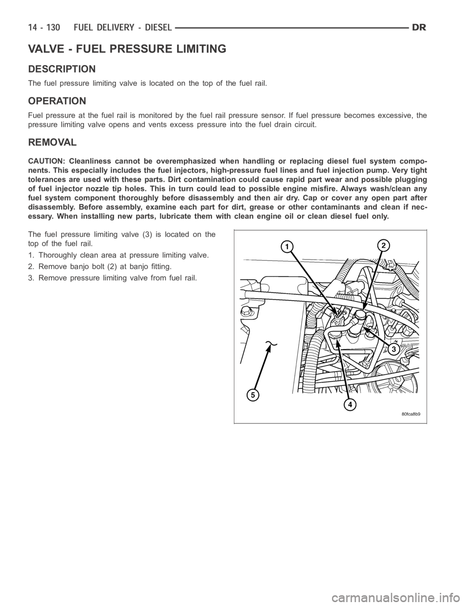
The fuel pressure limiting valve (3) is located on the
top of the fuel rail.
1. Thoroughly clean area at pressure limiting valve.
2. Remove banjo bolt (2) at banjo fitting.
3. Remove pressure limiting valve from fuel rail.
Page 2381 of 5267
INSTALLATION
1. Clean out machined hole in back of timing gear
housing.
2. Apply a small amount of engine oil to sensor O-ring
and sensor hole.
3. Install sensor into timing gear housing with a slight
rocking action. Do not twist sensor into position as
damagetoO-ringmayresult.
CAUTION: Before tightening sensor mounting bolt,
be sure sensor is completely flush to back of tim-
ing gear housing (cover). Remove (cover) if sensor
is not flush, damage to sensor mounting tang may
result.
4. Install mounting bolt and tighten. Torque to 9 Nꞏm
(80 in. lbs.).
5. Connect electrical connector (5) to sensor.
Page 2384 of 5267
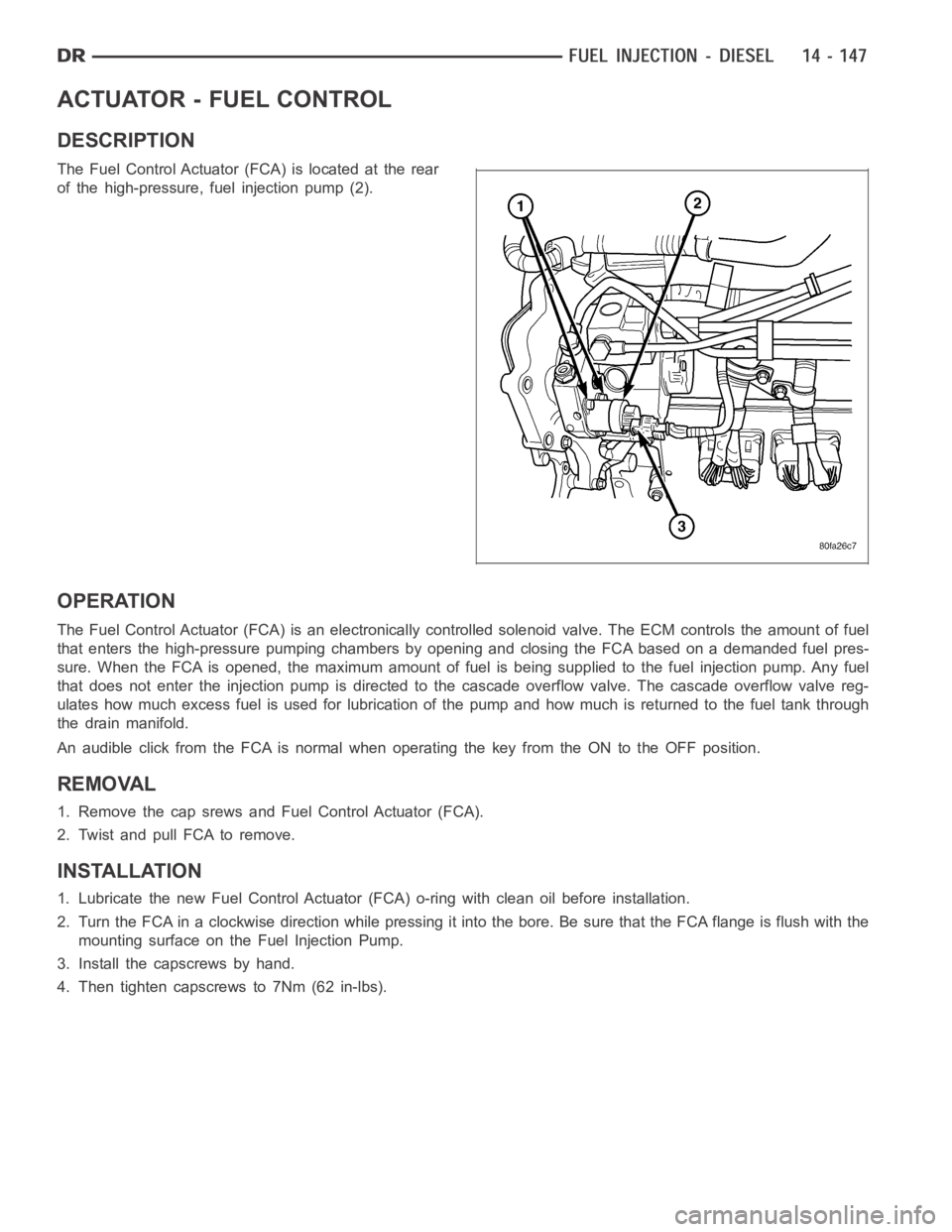
ACTUATOR - FUEL CONTROL
DESCRIPTION
The Fuel Control Actuator (FCA) is located at the rear
of the high-pressure, fuel injection pump (2).
OPERATION
The Fuel Control Actuator (FCA) is an electronically controlled solenoidvalve. The ECM controls the amount of fuel
that enters the high-pressure pumping chambers by opening and closing theFCA based on a demanded fuel pres-
sure. When the FCA is opened, the maximum amount of fuel is being supplied tothe fuel injection pump. Any fuel
that does not enter the injection pump is directed to the cascade overflow valve. The cascade overflow valve reg-
ulates how much excess fuel is used for lubrication of the pump and how much is returned to the fuel tank through
the drain manifold.
An audible click from the FCA is normal when operating the key from the ON to the OFF position.
REMOVAL
1. Remove the cap srews and Fuel Control Actuator (FCA).
2. Twist and pull FCA to remove.
INSTALLATION
1. Lubricate the new Fuel Control Actuator (FCA) o-ring with clean oil before installation.
2. Turn the FCA in a clockwise direction while pressing it into the bore. Be sure that the FCA flange is flush with the
mounting surface on the Fuel Injection Pump.
3. Install the capscrews by hand.
4. Then tighten capscrews to 7Nm (62 in-lbs).
Page 2391 of 5267
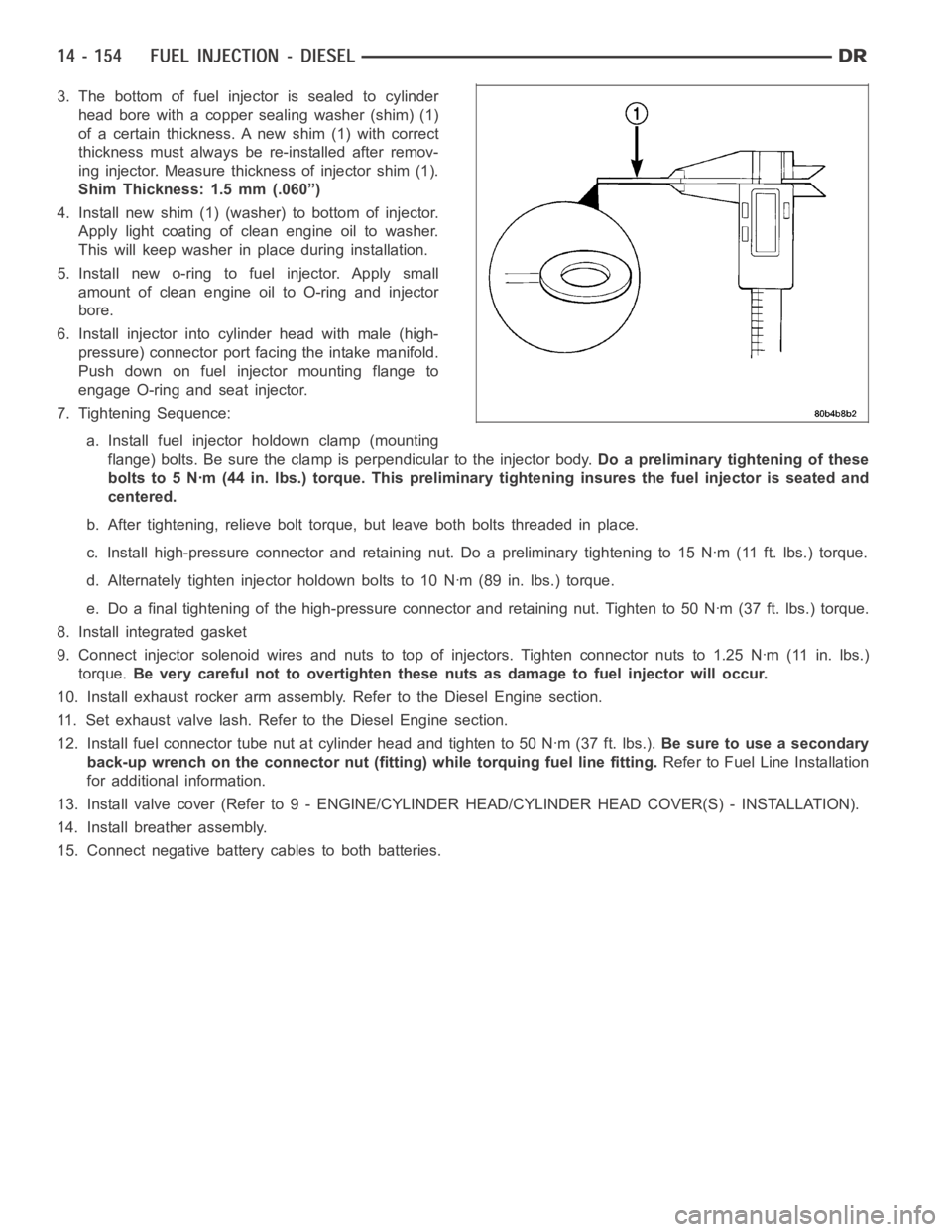
3. The bottom of fuel injector is sealed to cylinder
head bore with a copper sealing washer (shim) (1)
of a certain thickness. A new shim (1) with correct
thickness must always be re-installed after remov-
ing injector. Measure thickness of injector shim (1).
Shim Thickness: 1.5 mm (.060”)
4. Install new shim (1) (washer) to bottom of injector.
Apply light coating of clean engine oil to washer.
This will keep washer in place during installation.
5. Install new o-ring to fuel injector. Apply small
amount of clean engine oil to O-ring and injector
bore.
6. Install injector into cylinder head with male (high-
pressure) connector port facing the intake manifold.
Push down on fuel injector mounting flange to
engage O-ring and seat injector.
7. Tightening Sequence:
a. Install fuel injector holdown clamp (mounting
flange) bolts. Be sure the clamp is perpendicular to the injector body.Do a preliminary tightening of these
bolts to 5 Nꞏm (44 in. lbs.) torque. This preliminary tightening insures the fuel injector is seated and
centered.
b. After tightening, relieve bolt torque, but leave both bolts threaded inplace.
c. Install high-pressure connector and retaining nut. Do a preliminary tightening to 15 Nꞏm (11 ft. lbs.) torque.
d. Alternately tighten injector holdown bolts to 10 Nꞏm (89 in. lbs.) torque.
e. Do a final tightening of the high-pressure connector and retaining nut.Tighten to 50 Nꞏm (37 ft. lbs.) torque.
8. Install integrated gasket
9. Connect injector solenoid wires and nuts to top of injectors. Tighten connector nuts to 1.25 Nꞏm (11 in. lbs.)
torque.Be very careful not to overtighten these nuts as damage to fuel injector willoccur.
10. Install exhaust rocker arm assembly. Refer to the Diesel Engine section.
11. Set exhaust valve lash. Refer to the Diesel Engine section.
12. Install fuel connector tube nut at cylinder head and tighten to 50 Nꞏm (37ft.lbs.).Be sure to use a secondary
back-up wrench on the connector nut (fitting) while torquing fuel line fitting.Refer to Fuel Line Installation
for additional information.
13. Install valve cover (Refer to 9 - ENGINE/CYLINDER HEAD/CYLINDER HEAD COVER(S) - INSTALLATION).
14. Install breather assembly.
15. Connect negative battery cables to both batteries.