Page 2392 of 5267

FUEL INJECTOR RAIL
DESCRIPTION
The fuel injector rail is bolted to the top of the intake manifold.
OPERATION
The fuel rail is used as a distribution device to supply high-pressure fuelto the high-pressure fuel lines.
REMOVAL
CAUTION: Cleanliness cannot be overemphasized when handling or replacingdieselfuelsystemcompo-
nents. This especially includes the fuel injectors, high-pressure fuel lines and fuel injection pump. Very tight
tolerances are used with these parts. Dirt contamination could cause rapid part wear and possible plugging
of fuel injector nozzle tip holes. This in turn could lead to possible engine misfire. Always wash/clean any
fuel system component thoroughly before disassembly and then air dry. Capor cover any open part after
disassembly. Before assembly, examine each part for dirt, grease or othercontaminants and clean if nec-
essary. When installing new parts, lubricate them with clean engine oil orclean diesel fuel only.
1. Disconnect both negative battery cables at both
batteries. Isolate ends of both cables.
2. Disconnect electrical connector at fuel pressure
sensor.
3. Remove banjo bolt at fuel limiting valve.
4. Disconnect necessary wiring harness retention
clips from intake manifold.
5. Lift 2 rubber covers to gain access to positive (+),
intake heater cable nuts. Remove 2 nuts and
remove 2 cables from studs.
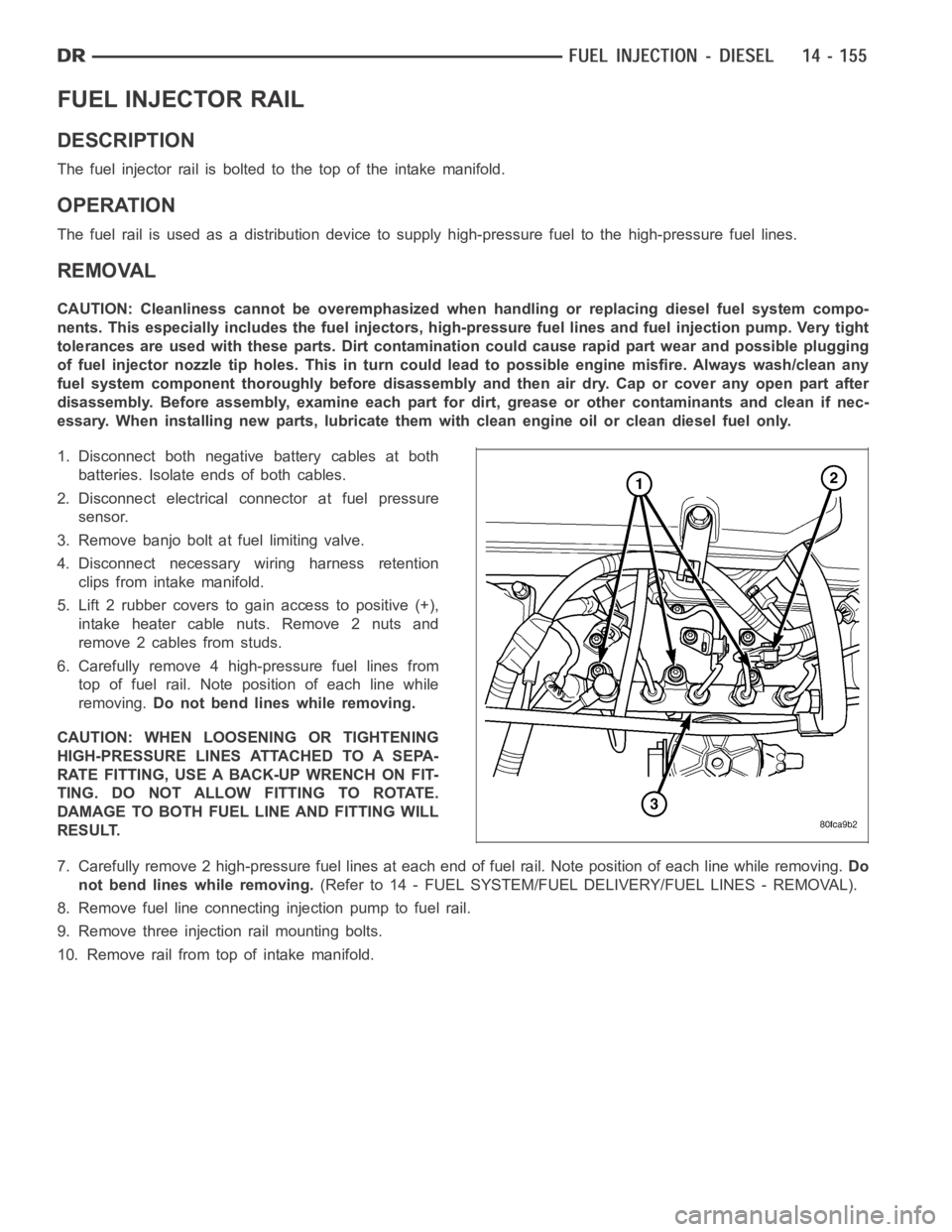
6. Carefully remove 4 high-pressure fuel lines from
top of fuel rail. Note position of each line while
removing.Do not bend lines while removing.
CAUTION: WHEN LOOSENING OR TIGHTENING
HIGH-PRESSURE LINES ATTACHED TO A SEPA-
RATE FITTING, USE A BACK-UP WRENCH ON FIT-
TING. DO NOT ALLOW FITTING TO ROTATE.
DAMAGE TO BOTH FUEL LINE AND FITTING WILL
RESULT.
7. Carefully remove 2 high-pressure fuel lines at each end of fuel rail. Note position of each line while removing.Do
not bend lines while removing.(Refer to 14 - FUEL SYSTEM/FUEL DELIVERY/FUEL LINES - REMOVAL).
8. Remove fuel line connectinginjection pump to fuel rail.
9. Remove three injection rail mounting bolts.
10. Remove rail from top of intake manifold.
Page 2398 of 5267
3. Lift 2 rubber covers (3) to gain access to 2 positive
(+) cable nuts.
4. Remove cable nut (6) (Fig #. ) and remove cable
from stud.
5. Remove wiring harness clips.
6. Remove engine oil dipstick tube bracket from air
inlet connection and fuel filter housing.
7. Remove four housing mounting bolts (1) and
remove heater element assembly.
Page 2399 of 5267
INSTALLATION
If servicing the heater element, the entire block/ele-
ment assembly must be replaced.
CAUTION: The heater elements are no longer
grounded using an external ground strap. Ground-
ing is now accomplished using two electrically
conductive gaskets. Failure to use these gaskets
will result in faulty heater element operation.
1. Using 2 new gaskets, position element assembly
and air housing to intake manifold (2).
2. Install wire harness clips to intake connection stud.
3. Install 4 housing bolts (1) and tighten to 24 Nꞏm
(18 ft. lbs.) torque.
4. Connect 2 positive (+) heater cables (6) at cable
mounting studs.Do not allow either of the cable
eyelets to contact any other metal source other
than the cable nuts/studs.
5. Install engine oil dipstick tube and mounting bolt
(5).
6. Connect rubber connector hose and intake tube to
air intake housing. Tighten clamp bolts to 11 Nꞏm
(100 in. lbs.) torque.
7. Connect both negative battery cables at both
batteries.
Page 2403 of 5267
5. Check condition of sensor O-ring (2).
INSTALLATION
1. Check condition of sensor o-ring.
2. Lubricate sensor o-ring and sensor hole in intake
manifold cover with clean engine oil.
3. Clean sensor mounting area at intake manifold (1).
4. Position sensor (2) into intake manifold.
5. Install and tighten 2 sensor mounting screws to 1
Nꞏm (9 in. lbs.) torque.
6. Connect electrical connector to sensor.
Page 2406 of 5267
STEERING
TABLE OF CONTENTS
page page
STEERING
DESCRIPTION ................................. 2
OPERATION ................................... 2
DIAGNOSIS AND TESTING
POWER STEERING SYSTEM ................. 2
POWER STEERING FLOW AND PRESSURE . . . 4
SPECIAL TOOLS
STEERING .................................. 6COLUMN...............................7
GEAR - INDEPENDENT FRONT SUSPENSION..38
GEAR - LINK/COIL.......................43
LINKAGE - INDEPENDENT FRONT
SUSPENSION...........................62
LINKAGE - LINK/COIL....................66
PUMP.................................76
PUMP - SRT10..........................92
Page 2407 of 5267

STEERING
DESCRIPTION
CAUTION: MOPARATF+4 is to be used in the power steering system. No other power steering or auto-
matic transmission fluid is to be used in the system. Damage may result to the power steering pump and
system if any other fluid is used, and do not overfill.
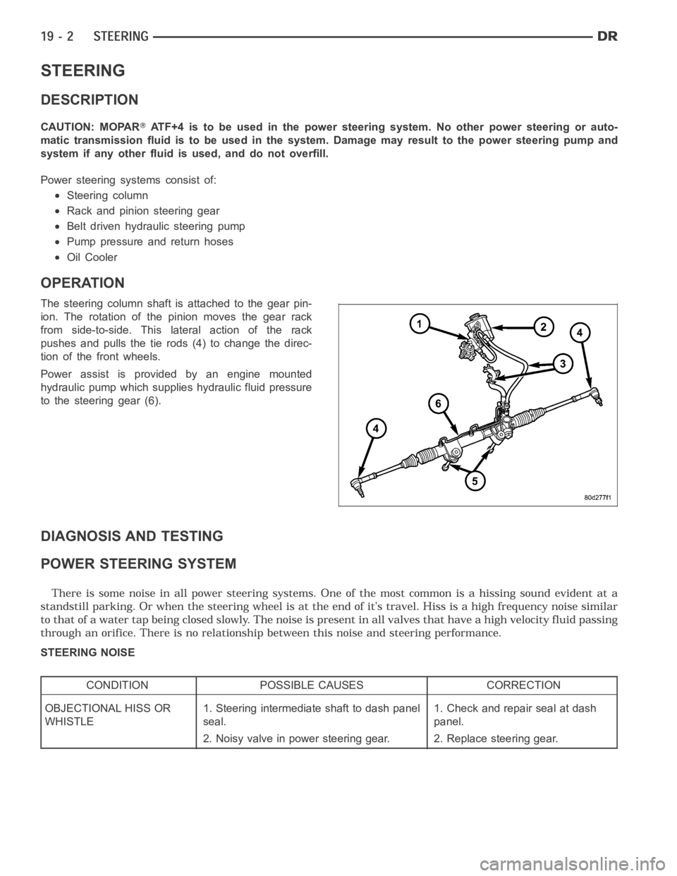
Power steering systems consist of:
Steering column
Rack and pinion steering gear
Belt driven hydraulic steering pump
Pump pressure and return hoses
Oil Cooler
OPERATION
The steering column shaft isattached to the gear pin-
ion. The rotation of the pinion moves the gear rack
from side-to-side. This lateral action of the rack
pushes and pulls the tie rods (4) to change the direc-
tion of the front wheels.
Power assist is provided by an engine mounted
hydraulic pump which supplies hydraulic fluid pressure
to the steering gear (6).
DIAGNOSIS AND TESTING
POWER STEERING SYSTEM
STEERING NOISE
CONDITION POSSIBLE CAUSES CORRECTION
OBJECTIONAL HISS OR
WHISTLE1. Steering intermediate shaft to dash panel
seal.1. Check and repair seal at dash
panel.
2. Noisy valve in power steering gear. 2. Replace steering gear.
Page 2447 of 5267

BUSHING
REMOVAL
1. Remove the steering gear (Refer to 19 - STEERING/GEAR - REMOVAL).
CAUTION: Do not overtighten the vise on the gear case.
2. Mount the steering gear in a soft jawed vise.
NOTE: If the bushings are seized a brass punch can be used to remove the bushings from the gear using
care not to strike the gear.
3. Remove the front mounting bushings.
4. Remove the rear mounting bushings.
5. Remove the steering gear from the vise and place it on the bench.
INSTALLATION
NOTE: Coat all bushings with a thin rubber lubricate oil prior to installation.
NOTE: A rubber mallet can be used to assist in the installation of the bushings once lubricated.
1. Coat the rear bushings with a thin rubber lubricate oil then install the rear bushings using a rubber mallet to seat
the bushings in the gear.
2. Coat the front bushings with a thin rubber lubricate oil then install thefront bushings using a rubber mallet to seat
the bushings in the gear.
3. Install the steering gear (Refer to 19 - STEERING/GEAR - INSTALLATION).
4. Adjust the toe position (if necessary) (Refer to 2 - SUSPENSION/WHEEL ALIGNMENT - STANDARD PROCE-
DURE).
Page 2448 of 5267

page page
GEAR - LINK/COIL
DESCRIPTION ................................ 44
OPERATION .................................. 44
REMOVAL .................................... 44
INSTALLATION ............................... 46
ADJUSTMENTS
ADJUSTMENT .............................. 47
SPECIFICATIONS
POWER STEERING GEAR ................... 47
TORQUE ................................... 48
SPECIAL TOOLS
POWER STEERING GEAR ................... 49
PITMAN SHAFT SEAL
REMOVAL
GAS ....................................... 51DIESEL .................................... 51
INSTALLATION
GAS ....................................... 52
DIESEL .................................... 53
STEERING GEAR INPUT SHAFT SEAL
REMOVAL .................................... 54
INSTALLATION ............................... 57
PITMAN SHAFT
REMOVAL
GAS ....................................... 59
DIESEL .................................... 59
INSTALLATION
GAS ....................................... 60
DIESEL .................................... 61