Page 5226 of 5267
REMOVAL
3.7L V-6 / 4.7L V-8
The PCV valve (6) is located on the oil filler tube (4).
Two locating tabs are located on the side of the valve
(2). These 2 tabs fit into a cam lock (3) in the oil filler
tube. An O-ring (1) seals the valve to the filler tube.
1. Disconnect PCV line/hose (5) by disconnecting rub-
ber hose at PCV valve fitting.
2. Remove PCV valve at oil filler tube by rotating PCV
valve downward (counter-clockwise) until locating
tabs (2) have been freed at cam lock (3). After tabs
have cleared, pull valve straight out from filler tube.
To prevent damage to PCV valve locating tabs,
valve must be pointed downward for removal.
Do not force valve from oil filler tube.
3. After valve is removed, check condition of valve
O-ring (1).
5.7L V-8
The PCV valve (4) is mounted into the top of the
intake manifold (1). This is located to the right / rear of
the throttle body (2).
Page 5227 of 5267

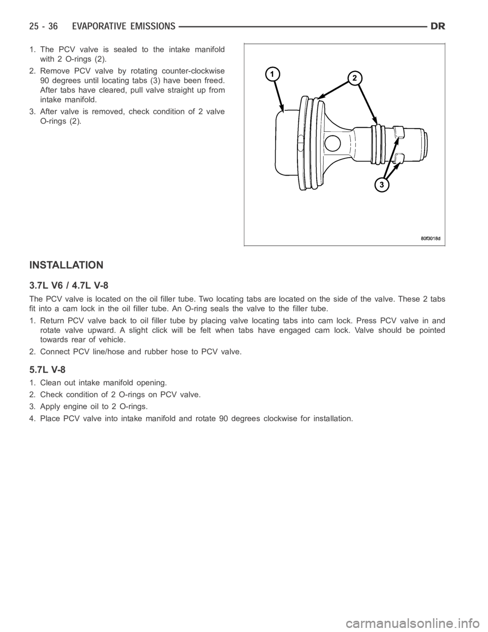
1. The PCV valve is sealed to the intake manifold
with 2 O-rings (2).
2. Remove PCV valve by rotating counter-clockwise
90 degrees until locating tabs (3) have been freed.
After tabs have cleared, pull valve straight up from
intake manifold.
3. After valve is removed, check condition of 2 valve
O-rings (2).
INSTALLATION
3.7L V6 / 4.7L V-8
The PCV valve is located on the oil filler tube. Two locating tabs are locatedonthesideofthevalve.These2tabs
fit into a cam lock in the oil filler tube.An O-ring seals the valve to the filler tube.
1. Return PCV valve back to oil filler tube by placing valve locating tabs into cam lock. Press PCV valve in and
rotate valve upward. A slight click will be felt when tabs have engaged cam lock. Valve should be pointed
towards rear of vehicle.
2. Connect PCV line/hose and rubber hose to PCV valve.
5.7L V-8
1. Clean out intake manifold opening.
2. Check condition of 2 O-rings on PCV valve.
3. Apply engine oil to 2 O-rings.
4. Place PCV valve into intake manifold and rotate 90 degrees clockwise forinstallation.
Page 5243 of 5267

VALVE-EGR
DESCRIPTION
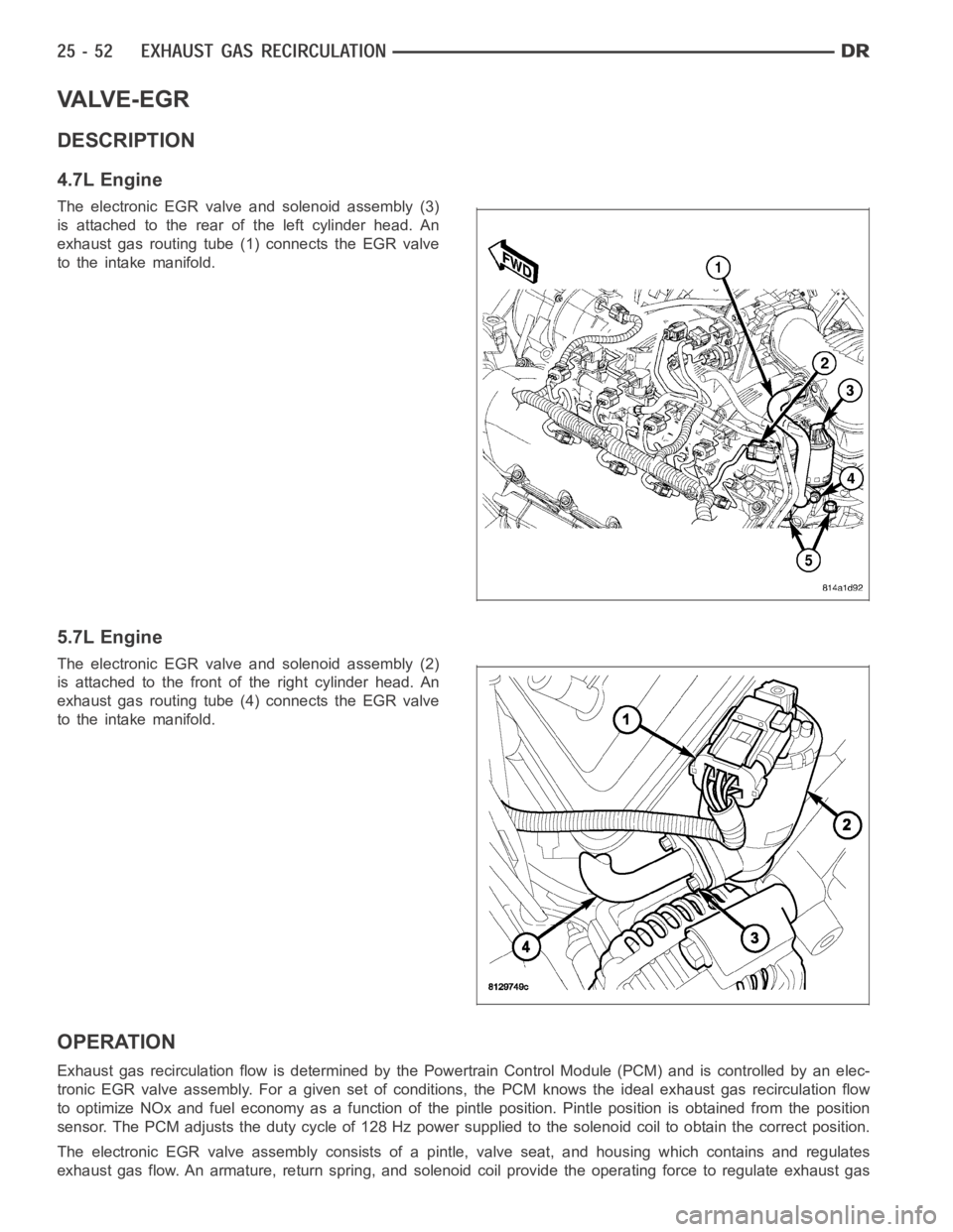
4.7L Engine
The electronic EGR valve and solenoid assembly (3)
is attached to the rear of the left cylinder head. An
exhaust gas routing tube (1) connects the EGR valve
to the intake manifold.
5.7L Engine
The electronic EGR valve and solenoid assembly (2)
is attached to the front of the right cylinder head. An
exhaust gas routing tube (4) connects the EGR valve
to the intake manifold.
OPERATION
Exhaust gas recirculation flow is determined by the Powertrain Control Module (PCM) and is controlled by an elec-
tronic EGR valve assembly. For a given set of conditions, the PCM knows the ideal exhaust gas recirculation flow
to optimize NOx and fuel economy as a function of the pintle position. Pintle position is obtained from the position
sensor. The PCM adjusts the duty cycle of 128 Hz power supplied to the solenoid coil to obtain the correct position.
The electronic EGR valve assembly consists of a pintle, valve seat, and housing which contains and regulates
exhaust gas flow. An armature, return spring, and solenoid coil provide the operating force to regulate exhaust gas
Page 5244 of 5267
flow by changing the pintle position. The solenoid coil assembly is wired in parallel with a diode that connects two
internal connectors.
REMOVAL
4.7L
The electronic EGR valve and solenoid assembly (4)
is attached to the rear of the left cylinder head. An
exhaust gas routing tube (3) connects the EGR valve
to the intake manifold.
1. Remove electrical connector (5) at top of EGR
valve solenoid.
2. Remove tube mounting bolt (1) at intake manifold.
3. Remove two bolts (4) connecting EGR tube (1) to
valve assembly.
4. Remove gasket located between EGR tube flange
and EGR valve assembly.
5. Remove two EGR valve mounting bolts (5).
6. Separate valve assembly (3) from engine.
7. Remove and discard metal gasket located between
cylinder head and valve assembly.