2006 DODGE RAM SRT-10 oil
[x] Cancel search: oilPage 5187 of 5267
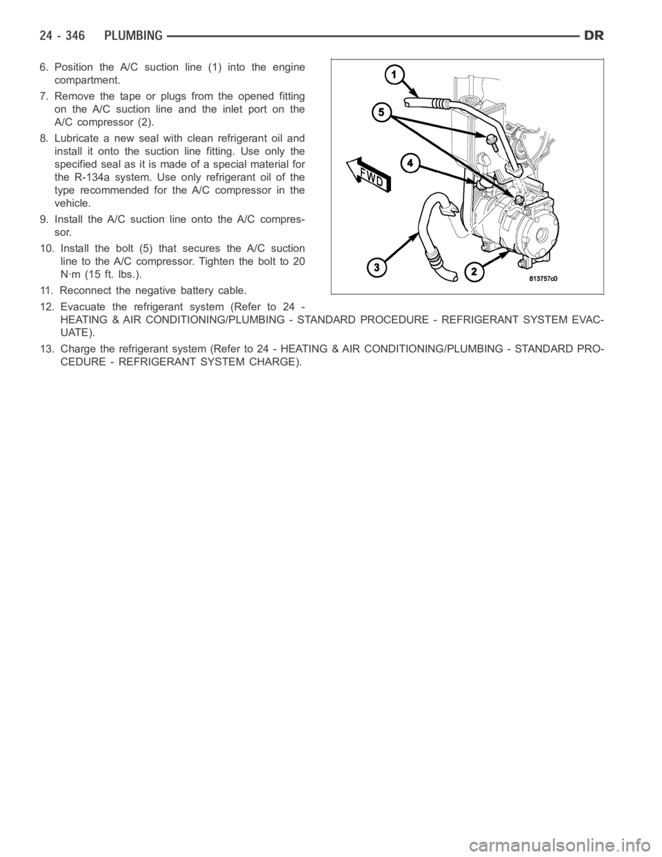
6. Position the A/C suction line (1) into the engine
compartment.
7. Remove the tape or plugs from the opened fitting
on the A/C suction line and the inlet port on the
A/C compressor (2).
8. Lubricate a new seal with clean refrigerant oil and
install it onto the suction line fitting. Use only the
specified seal as it is made of a special material for
the R-134a system. Use only refrigerant oil of the
type recommended for the A/C compressor in the
vehicle.
9. Install the A/C suction line onto the A/C compres-
sor.
10. Install the bolt (5) that secures the A/C suction
line to the A/C compressor. Tighten the bolt to 20
Nꞏm (15 ft. lbs.).
11. Reconnect the negative battery cable.
12. Evacuate the refrigerant system (Refer to 24 -
HEATING & AIR CONDITIONING/PLUMBING - STANDARD PROCEDURE - REFRIGERANT SYSTEM EVAC-
UATE).
13. Charge the refrigerant system (Refer to 24 - HEATING & AIR CONDITIONING/PLUMBING - STANDARD PRO-
CEDURE - REFRIGERANT SYSTEM CHARGE).
Page 5188 of 5267
OIL-A/C REFRIGERANT
DESCRIPTION
The refrigerant oil used in R-134a refrigerant systems is a synthetic-based, polyalkylene glycol (PAG), wax-free
lubricant. Mineral-based R-12 refrigerant oils are not compatible with PAG oils, and should never be introduced to
an R-134a refrigerant system.
There are different PAG oils available, and each contains a different additive package. Useonlyrefrigerant oil of the
same type as recommended to service the refrigerant system (always refer to the specification tagincluded with
the replacement A/C compressor or the A/C Underhood Specification Label located in the engine compartment).
The Denso 10S17 A/C compressor used in this vehicle when equipped with the 3.7L, 4.7L, 5.7L or 8.3L engine is
designed to use ND-8 PAG refrigerant oil. Use only this type of refrigerantoil when servicing the A/C compressor for
these engines.
The Visteon HS-18 A/C compressor used in this vehicle when equipped with 5.9L diesel engine is designed to use
VC-46 PAG refrigerant oil. Use only this type of refrigerant oil when servicing this A/C compressor.
OPERATION
After performing any refrigerant recovery or recycling operation, always replenish the refrigerant system with the
same amount of the recommended refrigerant oil as was removed. Too little refrigerant oil can cause A/C compres-
sor damage, and too much can reduce A/C system performance.
PAG refrigerant oil is more hygroscopic than mineral oil, and will absorb any moisture it comes into contact with,
even moisture in the air. The PAG oil container should always be kept tightly capped until it is ready to be used.
After use, recap the oil container immediately to prevent moisture contamination.
STANDARD PROCEDURE
REFRIGERANT OIL LEVEL
When an A/C system is assembled at the factory, all components except the A/C compressor are refrigerant oil free.
After the refrigerant system has been charged and operated, the refrigerant oil in the A/C compressor is dispersed
throughout the refrigerant system. The accumulator, A/C evaporator, A/Ccondenser and the A/C compressor will
each retain a significant amount of the needed refrigerant oil.
It is important to have the correct amount of refrigerant oil in the A/C system. This ensures proper lubrication of the
A/C compressor. Too little oil will result in damage to the A/C compressor,while too much oil will reduce the cooling
capacity of the A/C system and consequently result in higher discharge airtemperatures.
CAUTION: The refrigerant oil in the R-134a A/C system is unique depending on the A/C compressor used.
Use only PAG oils that are designed to work with R-134a refrigerant and the A/C compressor in the vehicle.
Always refer to the A/C Underhood Specification Label for the correct oil designation. The oil container
should be kept tightly capped until it is ready for use and then tightly capped after use to prevent contam-
ination from dirt and moisture. Refrigerant oil will quickly absorb any moisture it comes in contact with,
therefore, special effort must be used to keep all R-134a system components moisture-free. Moisture in the
refrigerant oil is very difficult toremove and will cause a reliability problem with the A/C compressor.
NOTE: Most reclaim/recycling equipment will measure the lubricant beingremoved during recovery. This
amount of lubricant should be added back into the system. Refer to the reclaim/recycling equipment man-
ufacturers instructions.
It will not be necessary to check the oil level in the A/C compressor or to addoil, unless there has been an oil loss.
An oil loss may occur due to a rupture or leak from a refrigerant line, a connector fitting, a component, or a com-
ponent seal. If a leak occurs, add 30 milliliters (1 fluid ounce) of refrigerant oil to the refrigerant system after the
repair has been made. Refrigerant oil loss will be evident at the leak pointby the presence of a wet, shiny surface
around the leak.
Refrigerant oil must be added when an accumulator, A/C evaporator or A/C condenser is replaced. See the Refrig-
erant Oil Capacities chart. When an A/C compressor is replaced, the refrigerant oil must be drained from the old
Page 5189 of 5267
compressor and measured. Drain all of the refrigerant oil from the new A/C compressor, then fill the new compres-
sor with the same amount of refrigerant oil that was drained out of the old compressor.
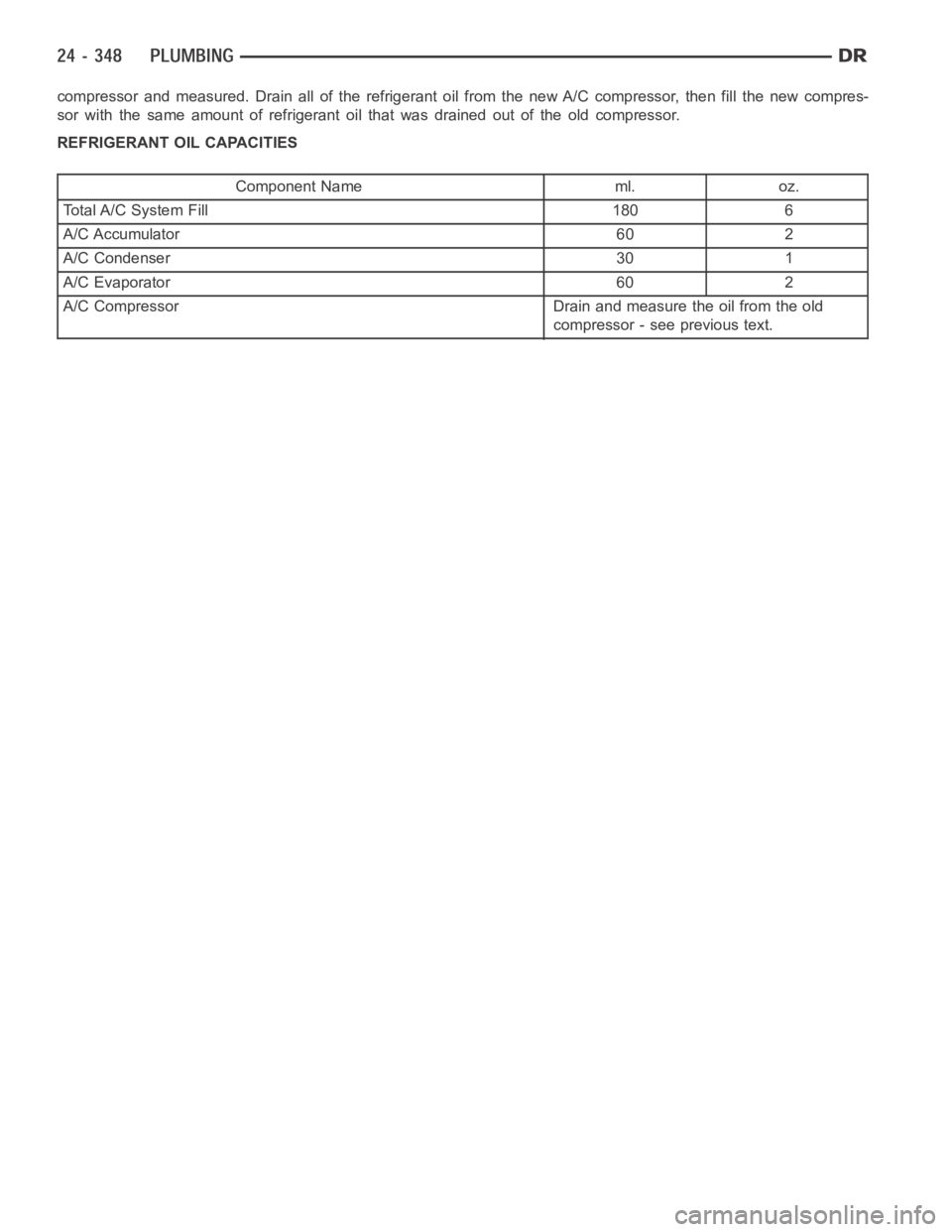
REFRIGERANT OIL CAPACITIES
Component Name ml. oz.
Total A/C System Fill 180 6
A/C Accumulator 60 2
A/C Condenser 30 1
A/C Evaporator 60 2
A/C Compressor Drain and measure the oil from the old
compressor - see previous text.
Page 5190 of 5267
REFRIGERANT-A/C
DESCRIPTION
The refrigerant used in this air conditioning system is a HydroFluoroCarbon (HFC), type R-134a. Unlike R-12, which
is a ChloroFluoroCarbon (CFC), R-134a refrigerant does not contain ozone-depleting chlorine. R-134a refrigerant is
a non-toxic, non-flammable, clear, and colorless liquefied gas.
Even though R-134a does not contain chlorine, it must be reclaimed and recycled just like CFC-type refrigerants.
This is because R-134a is a greenhouse gas and can contribute to global warming.
OPERATION
R-134a refrigerant is not compatiblewith R-12 refrigerant in an A/C system. Even a small amount of R-12 refrigerant
added to an R-134a refrigerant system will cause A/C compressor failure, refrigerant oil sludge or poor A/C system
performance. In addition, the polyalkylene glycol (PAG) synthetic refrigerant oils used in an R-134a refrigerant sys-
tem are not compatible with the mineral-based refrigerant oils used in an R-12 refrigerant system.
R-134a refrigerant system service ports, service tool couplers and refrigerant dispensing bottles have all been
designed with unique fittings to ensure that an R-134a refrigerant systemis not accidentally contaminated with the
wrong refrigerant (R-12). There are also labels posted in the engine compartment of the vehicle and on the A/C
compressor to identify that the A/C system is equipped with R-134a refrigerant.
Page 5201 of 5267
Engine RPM— A live reading of engine RPM to aid the user in accessing the Similar Conditions Window.
Adaptive Memory Factor— The PCM utilizes both Short Term Compensation and Long Term Adaptive to
calculate the Adaptive Memory Factor for total fuel correction.
Upstream O2S Volts— A live reading of the Oxygen Sensor to indicate its performance. For example, stuck
lean, stuck rich, etc.
SCW Time in Window (Similar Conditions Window Time in Window)—Atimer used by the PCM that
indicates that, after all Similar Conditions have been met, if there has been enough good engine running time
in the SCW without failure detected. This timer is used to increment a Good Trip.
Fuel System Good Trip Counter—ATripCounterusedtoturnOFFtheMILforFuelSystemDTCs.To
increment a Fuel System Good Trip, the engine must be in the Similar Conditions Window, Adaptive Memory
Factor must be less than calibrated threshold and the Adaptive Memory Factor must stay below that threshold
for a calibrated amount of time.
Test Done This Trip— Indicates that the monitor has already been run and completed during the current trip.
MISFIRE
Same Misfire Warm-Up State— Indicates if the misfire occurred when the engine was warmed up above
160° F (71.1°C).
In Similar Misfire Window— An indicator that ’Absolute MAP When Misfire Occurred’ and ’RPM When Mis-
fire Occurred’ are all in the same range when the failure occurred. Indicated by switching from ’NO’ to ’YES’.
Absolute MAP When Misfire Occurred— The stored MAP reading at the time of failure. Informs the user at
what engine load the failure occurred.
Absolute MAP— A live reading of engine load to aid the user in accessing the Similar Conditions Window.
RPM When Misfire Occurred— The stored RPM reading at the time of failure. Informs the user at what
engine RPM the failure occurred.
Engine RPM— A live reading of engine RPM to aid the user in accessing the Similar Conditions Window.
Adaptive Memory Factor— The PCM utilizes both Short Term Compensation and Long Term Adaptive to
calculate the Adaptive Memory Factor for total fuel correction.
200 Rev Counter— Counts 0–100 720 degree cycles.
SCW Cat 200 Rev Counter— Counts when in similar conditions.
SCW FTP 1000 Rev Counter— Counts 0–4 when in similar conditions.
Misfire Good Trip Counter— Counts up to three to turn OFF the MIL.
Misfire Data— Data collected during test.
Test Done This Trip— Indicates YES when the test is done.
NON-MONITORED CIRCUITS
The PCM does not monitor the following circuits, systems and conditions that could have malfunctions causing
driveability problems. The PCM might not store diagnostic trouble codes for these conditions. However, problems
with these systems may cause the PCM to store diagnostic trouble codes for other systems or components.EXAM-
PLE:a fuel pressure problem will not register a fault directly, but could causea rich/lean condition or misfire. This
could cause the PCM to store an oxygen sensor or misfire diagnostic troublecode
FUEL PRESSURE
The fuel pressure regulator controls fuel system pressure. The PCM cannotdetect a clogged fuel pump inlet filter,
clogged in-line fuel filter, or a pinched fuel supply or return line. However, these could result in a rich or lean con-
dition causing the PCM to store an oxygen sensor or fuel system diagnostic trouble code.
SECONDARY IGNITION CIRCUIT
The PCM cannot detect an inoperative ignition coil, fouled or worn spark plugs, ignition cross firing, or open spark
plug cables.
CYLINDER COMPRESSION
The PCM cannot detect uneven, low, or high engine cylinder compression.
Page 5202 of 5267
EXHAUST SYSTEM
The PCM cannot detect a plugged, restricted or leaking exhaust system, although it may set a fuel system fault.
FUEL INJECTOR MECHANICAL MALFUNCTIONS
The PCM cannot determine if a fuel injector is clogged, the needle is sticking or if the wrong injector is installed.
However, these could result in a rich or lean condition causing the PCM to store a diagnostic trouble code for either
misfire, an oxygen sensor, or the fuel system.
EXCESSIVE OIL CONSUMPTION
Although the PCM monitors engine exhaust oxygen content when the system isin closed loop, it cannot determine
excessive oil consumption.
THROTTLE BODY AIR FLOW
The PCM cannot detect a clogged or restricted air cleaner inlet or filter element.
VACUUM ASSIST
The PCM cannot detect leaks or restrictions in the vacuum circuits of vacuum assisted engine control system
devices. However, these could cause the PCM to store a MAP sensor diagnostic trouble code and cause a high idle
condition.
PCM SYSTEM GROUND
The PCM cannot determine a poor system ground. However, one or more diagnostic trouble codes may be gener-
ated as a result of this condition. The module should be mounted to the body at all times, also during diagnostic.
PCM CONNECTOR ENGAGEMENT
The PCM may not be able to determine spread or damaged connector pins. However, it might store diagnostic
trouble codes as a result of spread connector pins.
Page 5221 of 5267
VA LV E - P C V
DESCRIPTION
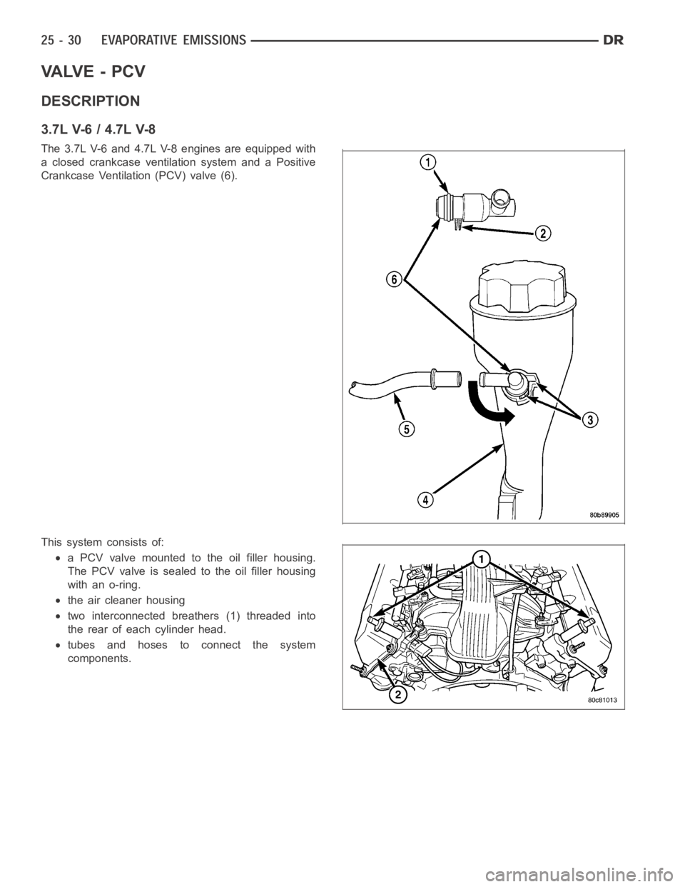
3.7L V-6 / 4.7L V-8
The 3.7L V-6 and 4.7L V-8 engines are equipped with
a closed crankcase ventilation system and a Positive
Crankcase Ventilation (PCV) valve (6).
This system consists of:
a PCV valve mounted to the oil filler housing.
The PCV valve is sealed to the oil filler housing
with an o-ring.
the air cleaner housing
two interconnected breathers (1) threaded into
the rear of each cylinder head.
tubes and hoses to connect the system
components.
Page 5224 of 5267
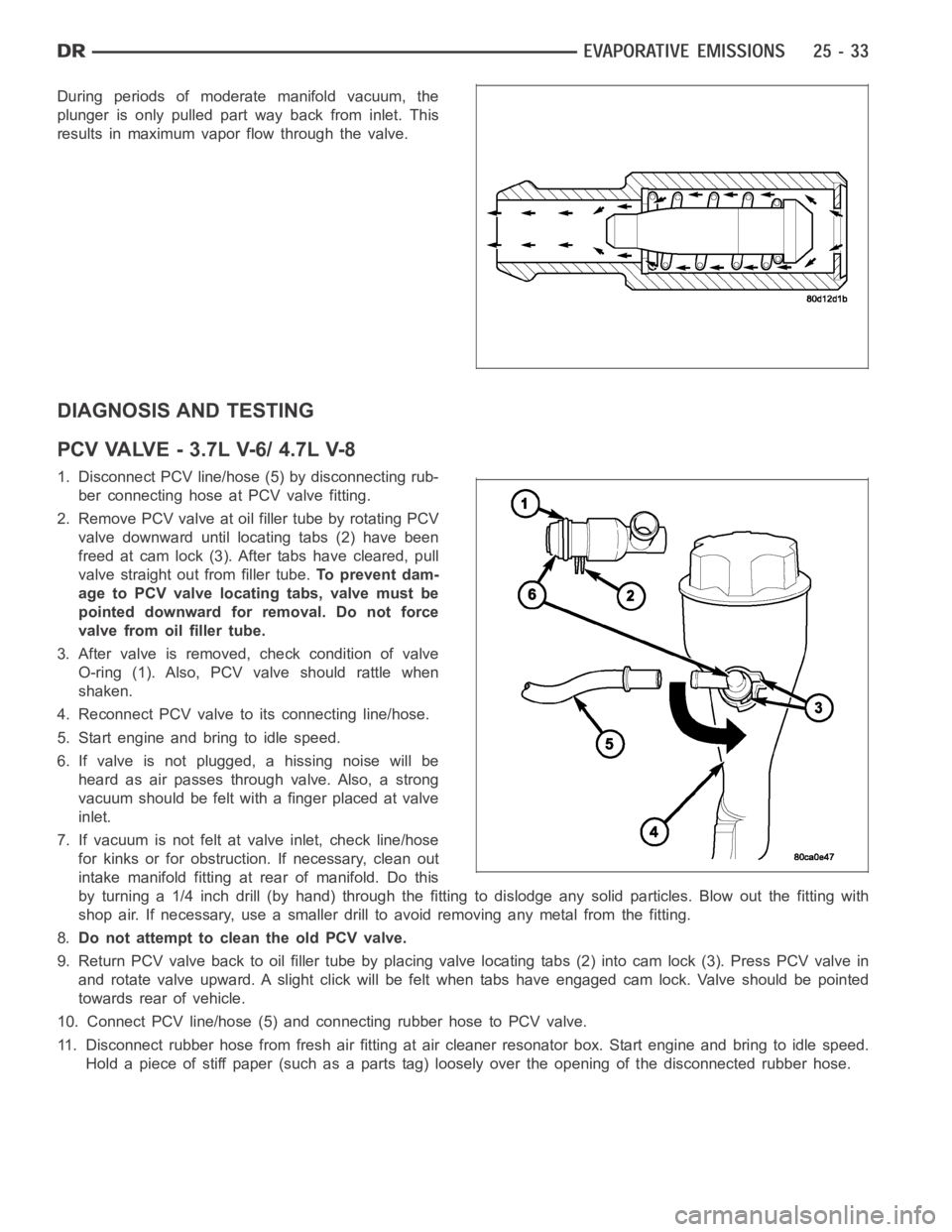
During periods of moderate manifold vacuum, the
plunger is only pulled part way back from inlet. This
results in maximum vapor flow through the valve.
DIAGNOSIS AND TESTING
PCVVALVE-3.7LV-6/4.7LV-8
1. Disconnect PCV line/hose (5) by disconnecting rub-
ber connecting hose at PCV valve fitting.
2. Remove PCV valve at oil filler tube by rotating PCV
valve downward until locating tabs (2) have been
freed at cam lock (3). After tabs have cleared, pull
valve straight out from filler tube.To prevent dam-
age to PCV valve locating tabs, valve must be
pointed downward for removal. Do not force
valve from oil filler tube.
3. After valve is removed, check condition of valve
O-ring (1). Also, PCV valve should rattle when
shaken.
4. Reconnect PCV valve to its connecting line/hose.
5. Start engine and bring to idle speed.
6. If valve is not plugged, a hissing noise will be
heard as air passes through valve. Also, a strong
vacuum should be felt with a finger placed at valve
inlet.
7. If vacuum is not felt at valve inlet, check line/hose
for kinks or for obstruction. If necessary, clean out
intake manifold fitting at rear of manifold. Do this
byturninga1/4inchdrill(byhand)throughthefittingtodislodgeanysolid particles. Blow out the fitting with
shop air. If necessary, use a smaller drill to avoid removing any metal fromthe fitting.
8.Do not attempt to clean the old PCV valve.
9. Return PCV valve back to oil filler tube by placing valve locating tabs (2) into cam lock (3). Press PCV valve in
and rotate valve upward. A slight click will be felt when tabs have engaged cam lock. Valve should be pointed
towards rear of vehicle.
10. Connect PCV line/hose (5) and connecting rubber hose to PCV valve.
11. Disconnect rubber hose from fresh air fitting at air cleaner resonatorbox. Start engine and bring to idle speed.
Hold a piece of stiff paper (such as a parts tag) loosely over the opening of the disconnected rubber hose.