Page 2141 of 5267
DESCRIPTION Nꞏm Ft. Lbs. In. Lbs.
Bolts-Turbocharger Oil Drain Tube-(Diesel) 24 18 -
Fitting-Turbocharger Oil Supply Line-(Diesel) 36 27 -
Nut-Turbocharger V-Band Clamp Cast Elbow to Turbocharger-
(Diesel)8-75
Nut-T-bolt Clamp Cast Elbow to Exhaust pipe-(Diesel) NOTE:
This is a One Time Use Only Nut.11 - 1 0 0
Turbocharger Oil Supply fitting at Turbocharger-(Diesel) 36 27 -
Turbocharger Oil Supply fitting at lube filter head-(Diesel) 24 18 -
Page 2145 of 5267
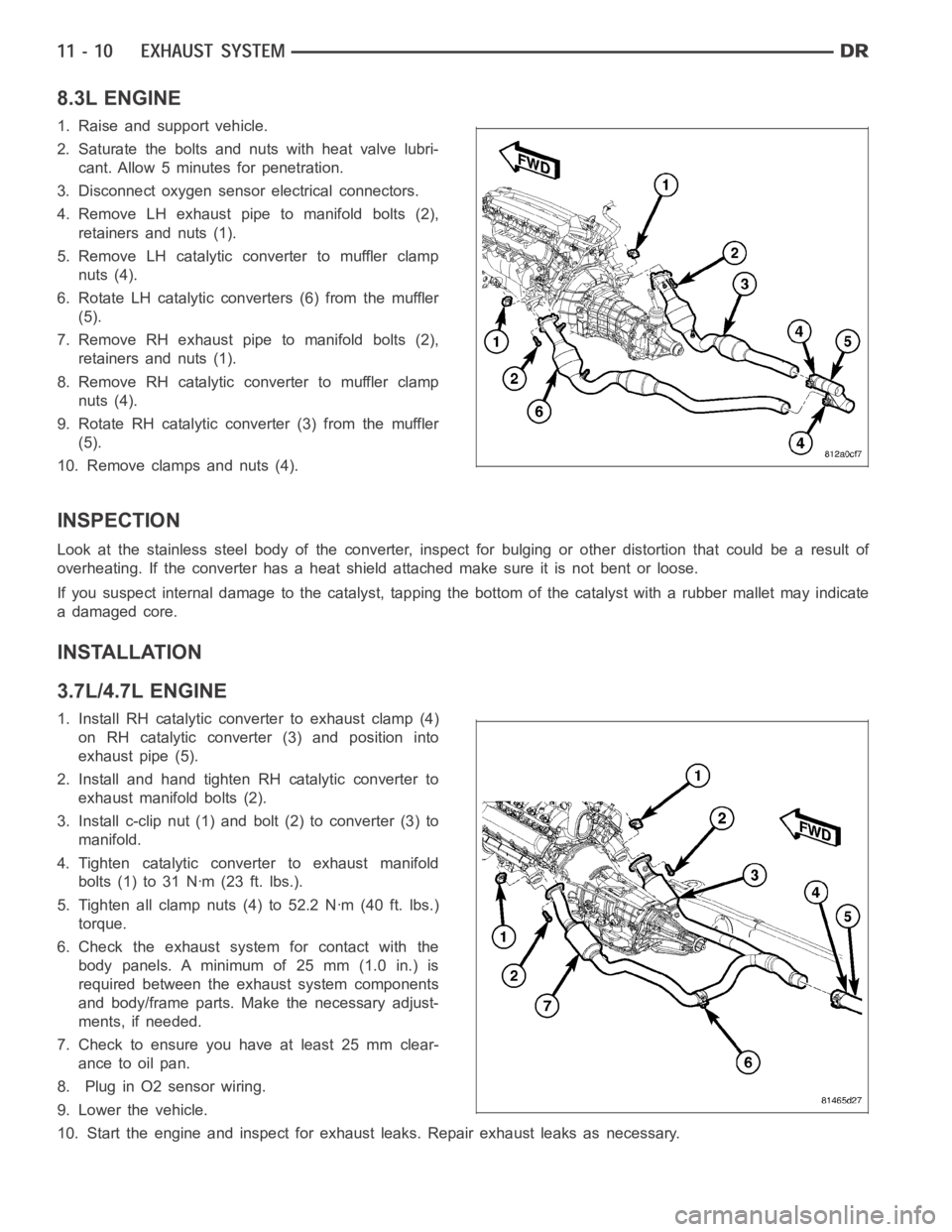
8.3L ENGINE
1. Raise and support vehicle.
2. Saturate the bolts and nuts with heat valve lubri-
cant. Allow 5 minutes for penetration.
3. Disconnect oxygen sensor electrical connectors.
4. Remove LH exhaust pipe to manifold bolts (2),
retainers and nuts (1).
5. Remove LH catalytic converter to muffler clamp
nuts (4).
6. Rotate LH catalytic converters (6) from the muffler
(5).
7. Remove RH exhaust pipe to manifold bolts (2),
retainers and nuts (1).
8. Remove RH catalytic converter to muffler clamp
nuts (4).
9. Rotate RH catalytic converter (3) from the muffler
(5).
10. Remove clamps and nuts (4).
INSPECTION
Look at the stainless steel body of the converter, inspect for bulging or other distortion that could be a result of
overheating. If the converter has a heat shield attached make sure it is notbent or loose.
If you suspect internal damage to the catalyst, tapping the bottom of the catalyst with a rubber mallet may indicate
a damaged core.
INSTALLATION
3.7L/4.7L ENGINE
1. Install RH catalytic converter to exhaust clamp (4)
on RH catalytic converter (3) and position into
exhaust pipe (5).
2. Install and hand tighten RH catalytic converter to
exhaust manifold bolts (2).
3. Install c-clip nut (1) and bolt (2) to converter (3) to
manifold.
4. Tighten catalytic converter to exhaust manifold
bolts(1)to31Nꞏm(23ft.lbs.).
5. Tighten all clamp nuts (4) to 52.2 Nꞏm (40 ft. lbs.)
torque.
6. Check the exhaust system for contact with the
body panels. A minimum of 25 mm (1.0 in.) is
required between the exhaust system components
and body/frame parts. Make the necessary adjust-
ments, if needed.
7. Check to ensure you have at least 25 mm clear-
ance to oil pan.
8. Plug in O2 sensor wiring.
9. Lower the vehicle.
10. Start the engine and inspect for exhaust leaks. Repair exhaust leaks asnecessary.
Page 2151 of 5267
HEAT SHIELDS
DESCRIPTION
There are two types of heat shields used. One is stamped steel the other is molded foil sheets. The shields attach
to the vehicle around the exhaust system to prevent heat from the exhaust system from entering the passenger
area and other areas where the heat can cause damage to other components.
REMOVAL
1. Raise and support the vehicle.
2. Remove the nuts or bolts holding the exhaust heat
shield to the floor pan, crossmember or bracket.
Page 2160 of 5267
TURBOCHARGER SYSTEM
DIAGNOSIS AND TESTING
TURBOCHARGER BOOST PRESSURE
Low turbocharger boost pressure can cause poor engine performance and driveability concerns. The following pro-
cedure will test the turbocharger boost pressure.
Causes of low boost pressure include the following:
Restricted air inlet system
Leak in charge air cooler system
Restricted/high pressure drop across charge air cooler
Damaged turbocharger compressor wheel housing
Turbocharger wastegate stuck open
Excessive exhaust restriction
Causes of excessively high boost pressure include:
Turbocharger wastegate stuck closed
Turbocharger wastegate signal line leaking or damaged
Damaged wastegate command valve O-rings
Wastegate command valve mechanically stuck in actuated position
Several Diagnostic Trouble Codes (DTCs) can be set that will indicate highor low system boost levels. There is a
DTC for circuit faults relating to the electronically controlled wastegate command valve.
(Refer to 11 - EXHAUST SYSTEM/TURBOCHARGER SYSTEM/CHARGE AIR COOLER AND PLUMBING - DIAG-
NOSIS AND TESTING) for diagnosing of low or high boost pressure due to leaks.
NOTE: If oil is present on either the inlet or exhaust side of the turbo charger, check the charge air cooler
for evidence of oil. Clean charge air cooler of any oil before starting the engine. Failure to do this can result
in severe engine damage.
Page 2163 of 5267
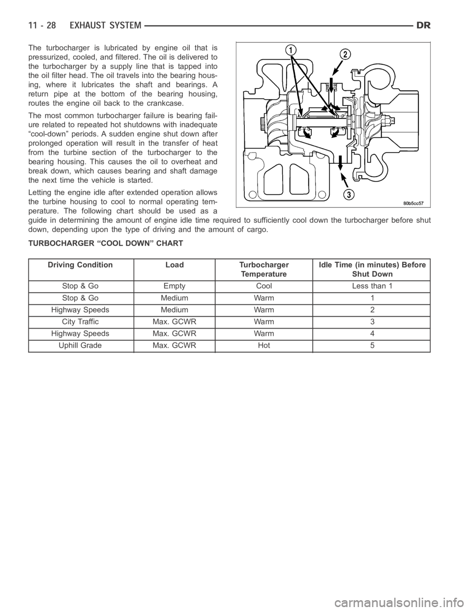
The turbocharger is lubricated by engine oil that is
pressurized, cooled, and filtered. The oil is delivered to
the turbocharger by a supply line that is tapped into
the oil filter head. The oil travels into the bearing hous-
ing, where it lubricates the shaft and bearings. A
return pipe at the bottom of the bearing housing,
routes the engine oil back to the crankcase.
The most common turbocharger failure is bearing fail-
ure related to repeated hot shutdowns with inadequate
“cool-down” periods. A sudden engine shut down after
prolonged operation will result in the transfer of heat
from the turbine section of the turbocharger to the
bearing housing. This causes the oil to overheat and
break down, which causes bearing and shaft damage
thenexttimethevehicleisstarted.
Letting the engine idle after extended operation allows
the turbine housing to cool to normal operating tem-
perature. The following chart should be used as a
guide in determining the amount of engine idle time required to sufficiently cool down the turbocharger before shut
down, depending upon the type of driving and the amount of cargo.
TURBOCHARGER “COOL DOWN” CHART
Driving Condition Load Turbocharger
TemperatureIdle Time (in minutes) Before
Shut Down
Stop & Go Empty Cool Less than 1
Stop & Go Medium Warm 1
Highway Speeds Medium Warm 2
City Traffic Max. GCWR Warm 3
Highway Speeds Max. GCWR Warm 4
Uphill Grade Max. GCWR Hot 5
Page 2164 of 5267
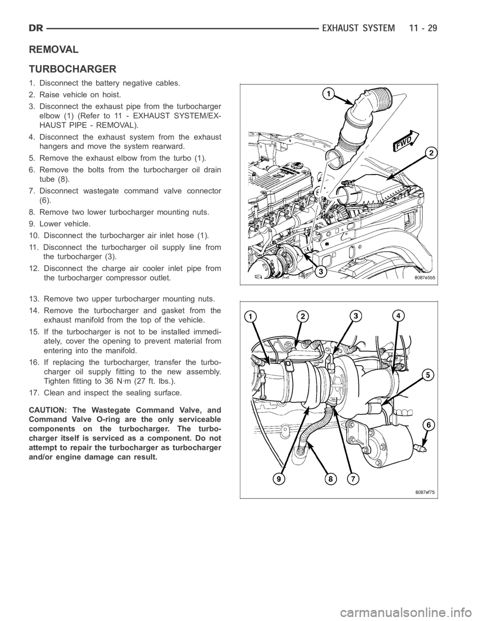
REMOVAL
TURBOCHARGER
1. Disconnect the battery negative cables.
2. Raise vehicle on hoist.
3. Disconnect the exhaust pipe from the turbocharger
elbow (1) (Refer to 11 - EXHAUST SYSTEM/EX-
HAUST PIPE - REMOVAL).
4. Disconnect the exhaust system from the exhaust
hangers and move the system rearward.
5. Remove the exhaust elbow from the turbo (1).
6. Remove the bolts from the turbocharger oil drain
tube (8).
7. Disconnect wastegate command valve connector
(6).
8. Remove two lower turbocharger mounting nuts.
9. Lower vehicle.
10. Disconnect the turbocharger air inlet hose (1).
11. Disconnect the turbocharger oil supply line from
the turbocharger (3).
12. Disconnect the charge air cooler inlet pipe from
the turbocharger compressor outlet.
13. Remove two upper turbocharger mounting nuts.
14. Remove the turbocharger and gasket from the
exhaust manifold from the top of the vehicle.
15. If the turbocharger is not to be installed immedi-
ately, cover the opening to prevent material from
entering into the manifold.
16. If replacing the turbocharger, transfer the turbo-
charger oil supply fitting to the new assembly.
Tighten fitting to 36 Nꞏm (27 ft. lbs.).
17. Clean and inspect the sealing surface.
CAUTION: The Wastegate Command Valve, and
Command Valve O-ring are the only serviceable
components on the turbocharger. The turbo-
charger itself is serviced as a component. Do not
attempt to repair the turbocharger as turbocharger
and/or engine damage can result.
Page 2165 of 5267
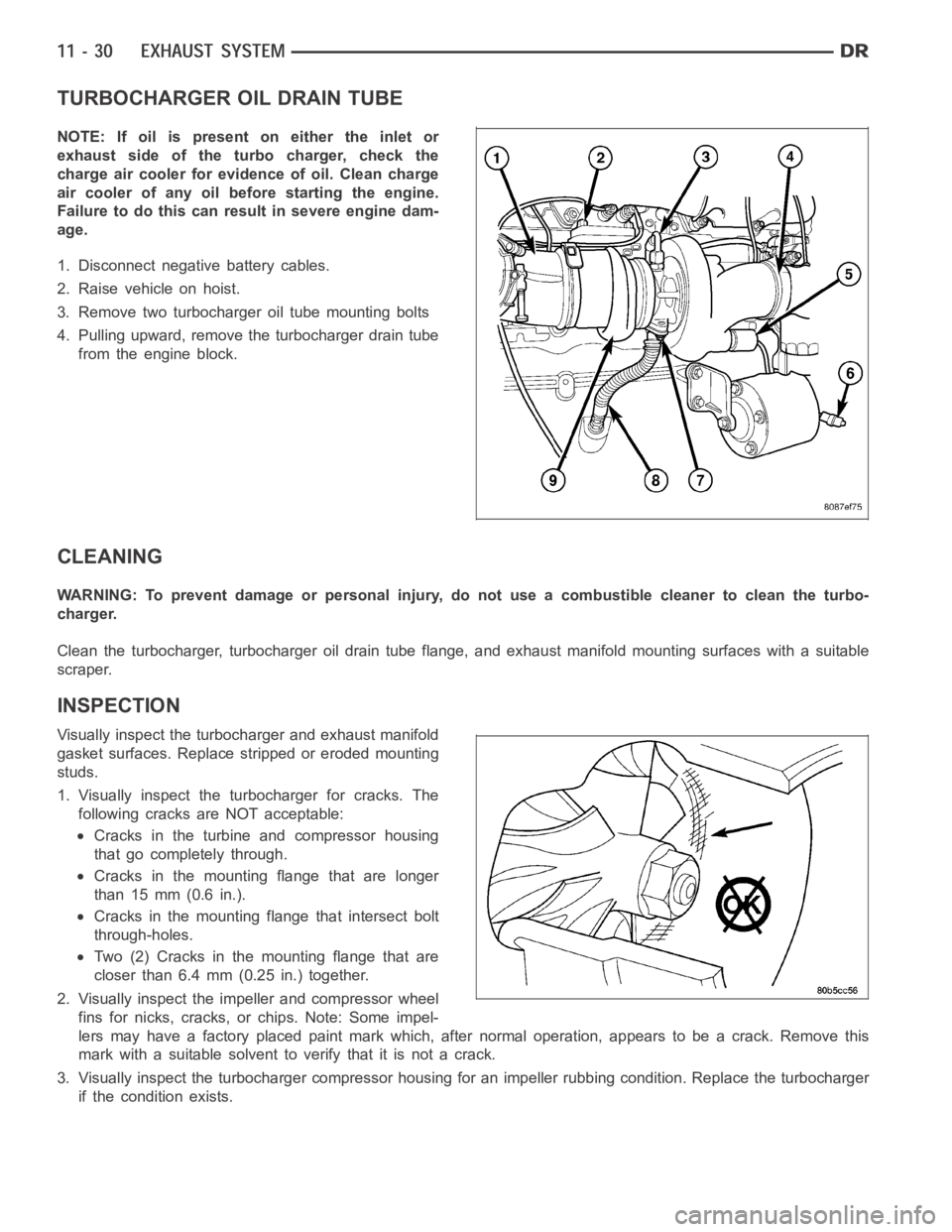
TURBOCHARGER OIL DRAIN TUBE
NOTE: If oil is present on either the inlet or
exhaust side of the turbo charger, check the
charge air cooler for evidence of oil. Clean charge
air cooler of any oil before starting the engine.
Failure to do this can result in severe engine dam-
age.
1. Disconnect negative battery cables.
2. Raise vehicle on hoist.
3. Remove two turbocharger oil tube mounting bolts
4. Pulling upward, remove the turbocharger drain tube
from the engine block.
CLEANING
WARNING: To prevent damage or personal injury, do not use a combustible cleaner to clean the turbo-
charger.
Clean the turbocharger, turbocharger oil drain tube flange, and exhaust manifold mounting surfaces with a suitable
scraper.
INSPECTION
Visually inspect the turbocharger and exhaust manifold
gasket surfaces. Replace stripped or eroded mounting
studs.
1. Visually inspect the turbocharger for cracks. The
following cracks are NOT acceptable:
Cracks in the turbine and compressor housing
that go completely through.
Cracks in the mounting flange that are longer
than 15 mm (0.6 in.).
Cracks in the mounting flange that intersect bolt
through-holes.
Two (2) Cracks in the mounting flange that are
closer than 6.4 mm (0.25 in.) together.
2. Visually inspect the impeller and compressor wheel
fins for nicks, cracks, or chips. Note: Some impel-
lers may have a factory placed paint mark which, after normal operation, appears to be a crack. Remove this
mark with a suitable solvent to verify that it is not a crack.
3. Visually inspect the turbocharger compressor housing for an impeller rubbing condition. Replace the turbocharger
if the condition exists.
Page 2166 of 5267
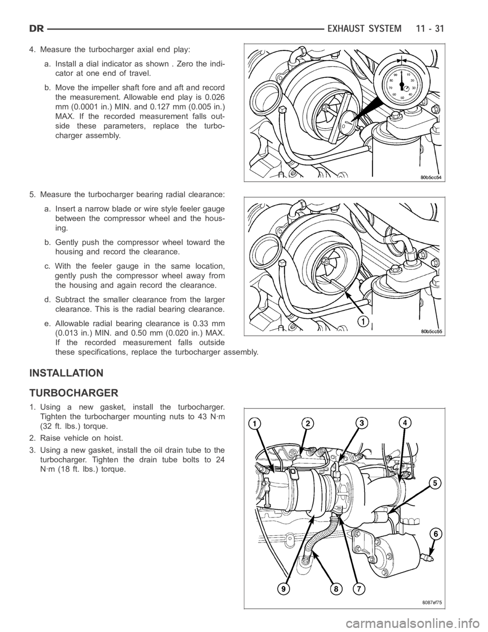
4. Measure the turbocharger axial end play:
a. Install a dial indicator as shown . Zero the indi-
cator at one end of travel.
b. Move the impeller shaft fore and aft and record
the measurement. Allowable end play is 0.026
mm (0.0001 in.) MIN. and 0.127 mm (0.005 in.)
MAX. If the recorded measurement falls out-
side these parameters, replace the turbo-
charger assembly.
5. Measure the turbocharger bearing radial clearance:
a. Insert a narrow blade or wire style feeler gauge
between the compressor wheel and the hous-
ing.
b. Gently push the compressor wheel toward the
housing and record the clearance.
c. With the feeler gauge in the same location,
gently push the compressor wheel away from
the housing and again record the clearance.
d. Subtract the smaller clearance from the larger
clearance. This is the radial bearing clearance.
e. Allowable radial bearing clearance is 0.33 mm
(0.013 in.) MIN. and 0.50 mm (0.020 in.) MAX.
If the recorded measurement falls outside
these specifications, replace the turbocharger assembly.
INSTALLATION
TURBOCHARGER
1. Using a new gasket, install the turbocharger.
Tighten the turbocharger mounting nuts to 43 Nꞏm
(32 ft. lbs.) torque.
2. Raise vehicle on hoist.
3. Using a new gasket, install the oil drain tube to the
turbocharger. Tighten the drain tube bolts to 24
Nꞏm (18 ft. lbs.) torque.