Page 2390 of 5267
14. Remove and discard injector sealing washer (2).
This washer should be located on tip of injector,
or may have remained in the injector bore..
INSTALLATION
1.Inspect fuel injector:
a. Look for burrs on injector inlet.
b. Check nozzle holes for hole erosion or plugging.
c. Inspect end of nozzle for burrs or rough machine marks.
d. Look for cracks at nozzle end.
e. If any of these conditions occur, replace injector.
2. Thoroughly clean fuel injector cylinder head bore. Blow out bore hole with compressed air.
Page 2395 of 5267
1. Disconnect electrical connector at sensor.
2. Remove two Torx-type mounting screws (3).
3. Remove sensor from air cleaner cover.
4. Check condition of sensor O-ring (2).
Page 2396 of 5267
INSTALLATION
1. Check condition of sensor O-ring.
2. Position sensor into top of air cleaner cover with a
slight twisting action.
3. Install 2 mounting screws (3).
4. Install electrical connector (2).
Page 2407 of 5267
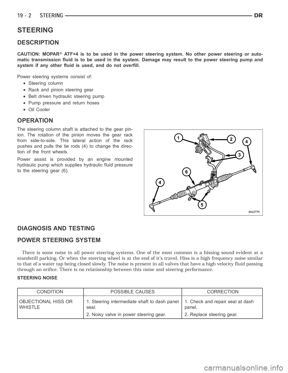
STEERING
DESCRIPTION
CAUTION: MOPARATF+4 is to be used in the power steering system. No other power steering or auto-
matic transmission fluid is to be used in the system. Damage may result to the power steering pump and
system if any other fluid is used, and do not overfill.
Power steering systems consist of:
Steering column
Rack and pinion steering gear
Belt driven hydraulic steering pump
Pump pressure and return hoses
Oil Cooler
OPERATION
The steering column shaft isattached to the gear pin-
ion. The rotation of the pinion moves the gear rack
from side-to-side. This lateral action of the rack
pushes and pulls the tie rods (4) to change the direc-
tion of the front wheels.
Power assist is provided by an engine mounted
hydraulic pump which supplies hydraulic fluid pressure
to the steering gear (6).
DIAGNOSIS AND TESTING
POWER STEERING SYSTEM
STEERING NOISE
CONDITION POSSIBLE CAUSES CORRECTION
OBJECTIONAL HISS OR
WHISTLE1. Steering intermediate shaft to dash panel
seal.1. Check and repair seal at dash
panel.
2. Noisy valve in power steering gear. 2. Replace steering gear.
Page 2408 of 5267
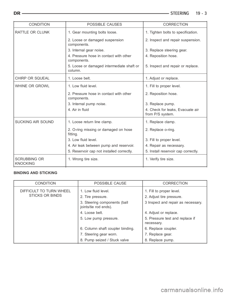
CONDITION POSSIBLE CAUSES CORRECTION
RATTLE OR CLUNK 1. Gear mounting bolts loose. 1. Tighten bolts to specification.
2. Loose or damaged suspension
components.2. Inspect and repair suspension.
3. Internal gear noise. 3. Replace steering gear.
4. Pressure hose in contact with other
components.4. Reposition hose.
5. Loose or damaged intermediate shaft or
column.5. Inspect and repair or replace.
CHIRP OR SQUEAL 1. Loose belt. 1. Adjust or replace.
WHINE OR GROWL 1. Low fluid level. 1. Fill to proper level.
2. Pressure hose in contact with other
components.2. Reposition hose.
3. Internal pump noise. 3. Replace pump.
4. Air in fluid 4. Check for leaks, Evacuate air
from P/S system.
SUCKING AIR SOUND 1. Loose return line clamp. 1. Replace clamp.
2. O-ring missing or damaged on hose
fitting.2. Replace o-ring.
3. Low fluid level. 3. Fill to proper level.
4. Air leak between pump and reservoir. 4. Repair as necessary.
5. Reservoir cap not installed correctly. 5. Install reservoir cap correctly.
SCRUBBING OR
KNOCKING1. Wrong tire size. 1. Verify tire size.
BINDING AND STICKING
CONDITION POSSIBLE CAUSE CORRECTION
DIFFICULT TO TURN WHEEL
STICKS OR BINDS1. Low fluid level. 1. Fill to proper level.
2. Tire pressure. 2. Adjust tire pressure.
3. Steering components (ball
joints/tie rod ends).3 Inspect and repair as necessary.
4. Loose belt. 4. Adjust or replace.
5. Low pump pressure. 5. Pressure test and replace if
necessary.
6. Column shaft coupler binding. 6. Replace coupler.
7. Steering gear worn. 7. Replace gear.
8. Pump seized / Stuck valve 8. Replace pump.
Page 2409 of 5267
INSUFFICIENT ASST. OR POOR RETURN TO CENTER
CONDITION POSSIBLE CAUSE CORRECTION
HARD TURNING OR MOMENTARY
INCREASE IN TURNING EFFORT1. Tire pressure. 1. Adjust tire pressure.
2. Low fluid level. 2. Fill to proper level.
3. Loose belt. 3. Adjust or replace.
4. Low pump pressure. 4. Pressure test and repair as
necessary.
5. Internal gear leak. 5. Replace gear.
STEERING WHEEL DOES NOT
WANT TO RETURN TO CENTER
POSITION1. Tire pressure. 1. Adjust tire pressure.
2. Wheel alignment. 2. Align front end.
3. Lack of lubrication. 3. Inspect and lubricate suspension
components.
4. High friction in steering gear. 4. Replace gear.
LOOSE STEERING AND VEHICLE LEAD
CONDITION POSSIBLE CAUSE CORRECTION
EXCESSIVE PLAY IN STEERING
WHEEL1. Worn or loose suspension or
steering components.1. Inspect and repair as necessary.
2. Worn or loose wheel bearings. 2. Inspect and repair or adjust
bearings.
3. Steering gear mounting. 3. Tighten gear mounting bolts to
specification.
4. Gear out of adjustment. 4. Replace gear.
5. Worn or loose steering coupler. 5. Inspect and replace as
necessary.
VEHICLE PULLS OR LEADS TO
ONE SIDE.1. Tire Pressure. 1. Adjust tire pressure.
2. Radial tire lead. 2. Rotate tires.
3. Brakes dragging. 3. Repair as necessary.
4. Wheel alignment. 4. Align front end.
5. Steering gear valve bias. 5. Replace steering gear.
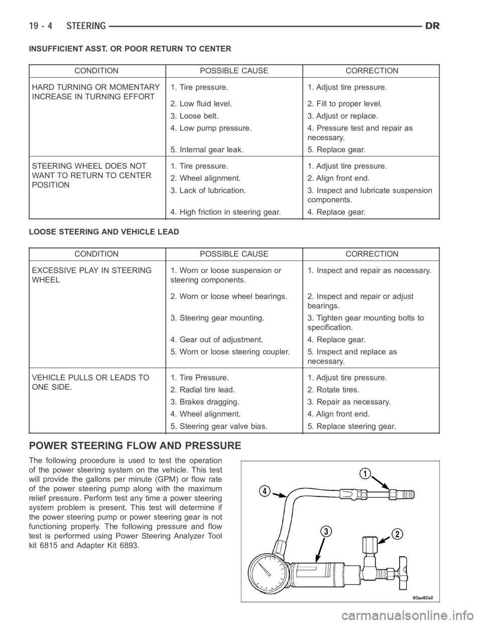
POWER STEERING FLOW AND PRESSURE
The following procedure is used to test the operation
of the power steering system on the vehicle. This test
will provide the gallons per minute (GPM) or flow rate
of the power steering pump along with the maximum
relief pressure. Perform test any time a power steering
system problem is present. This test will determine if
the power steering pump or power steering gear is not
functioning properly. The following pressure and flow
test is performed using Power Steering Analyzer Tool
kit 6815 and Adapter Kit 6893.
Page 2410 of 5267
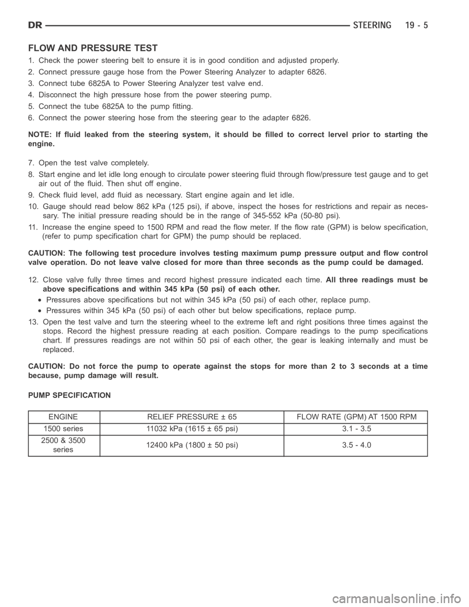
FLOW AND PRESSURE TEST
1. Check the power steering belt to ensure it is in good condition and adjusted properly.
2. Connect pressure gauge hose from the Power Steering Analyzer to adapter6826.
3. Connect tube 6825A to Power Steering Analyzer test valve end.
4. Disconnect the high pressure hose from the power steering pump.
5. Connect the tube 6825A to the pump fitting.
6. Connect the power steering hose from the steering gear to the adapter 6826.
NOTE: If fluid leaked from the steering system, it should be filled to correct lervel prior to starting the
engine.
7. Open the test valve completely.
8. Start engine and let idle long enough to circulate power steering fluid through flow/pressure test gauge and to get
air out of the fluid. Then shut off engine.
9. Check fluid level, add fluid as necessary. Start engine again and let idle.
10. Gauge should read below 862 kPa (125 psi), if above, inspect the hoses for restrictions and repair as neces-
sary. The initial pressure reading should be in the range of 345-552 kPa (50-80 psi).
11. Increase the engine speed to 1500 RPM and read the flow meter. If the flowrate (GPM) is below specification,
(refer to pump specification chart for GPM) the pump should be replaced.
CAUTION: The following test procedure involves testing maximum pump pressure output and flow control
valve operation. Do not leave valve closed for more than three seconds as the pump could be damaged.
12. Close valve fully three times and record highest pressure indicated each time.All three readings must be
above specifications and within 345 kPa (50 psi) of each other.
Pressures above specifications but not within 345 kPa (50 psi) of each other, replace pump.
Pressures within 345 kPa (50 psi) of each other but below specifications, replace pump.
13. Open the test valve and turn the steering wheel to the extreme left and right positions three times against the
stops. Record the highest pressure reading at each position. Compare readings to the pump specifications
chart. If pressures readings are not within 50 psi of each other, the gear isleaking internally and must be
replaced.
CAUTION: Do not force the pump to operate against the stops for more than 2 to3 seconds at a time
because, pump damage will result.
PUMP SPECIFICATION
ENGINE RELIEF PRESSURE ± 65 FLOW RATE (GPM) AT 1500 RPM
1500 series 11032 kPa (1615 ± 65 psi) 3.1 - 3.5
2500 & 3500
series12400 kPa (1800 ± 50 psi) 3.5 - 4.0
Page 2498 of 5267
PUMP - SRT10
DIAGNOSIS AND TESTING - HYDRAULIC FLOW AND PRESSURE
The following procedures are used to test the operation of the power steering and hydraulic fan systems on this
vehicle. These tests will provide the gallons per minute (GPM) or flow rateof the power steering pump along with
the maximum relief pressure at given points in the system. Perform the first test anytime a power steering system
problem is present and the second as necessary once the first test is completed. These tests will determine if the
power steering pump, hydraulic fan, or power steering gear is not functioning properly. They will also determine if
the flow coming out of the hydraulic fan motor is sufficient for the power steering gear. The following pressure and
flow tests are performed using the Power Steering Analyzer kit 6815 (with appropriate hoses) and Adapter kit 9091.
(Refer to 19 - STEERING - SPECIAL TOOLS)
FLOW AND PRESSURE TEST - AT POWER STEERING PUMP
1. Check power steering belt to ensure it is in good
condition and adjusted properly.
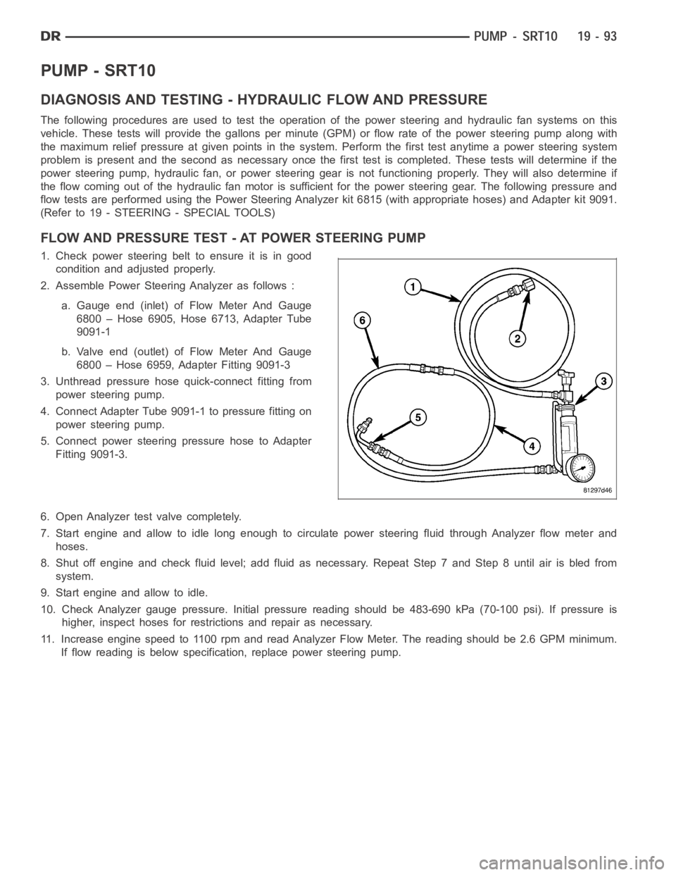
2. Assemble Power Steering Analyzer as follows :
a. Gauge end (inlet) of Flow Meter And Gauge
6800 – Hose 6905, Hose 6713, Adapter Tube
9091-1
b. Valve end (outlet) of Flow Meter And Gauge
6800 – Hose 6959, Adapter Fitting 9091-3
3. Unthread pressure hose quick-connect fitting from
power steering pump.
4. Connect Adapter Tube 9091-1 to pressure fitting on
power steering pump.
5. Connect power steering pressure hose to Adapter
Fitting 9091-3.
6. Open Analyzer test valve completely.
7. Start engine and allow to idle long enough to circulate power steering fluid through Analyzer flow meter and
hoses.
8. Shut off engine and check fluid level; add fluid as necessary. Repeat Step7andStep8untilairisbledfrom
system.
9. Start engine and allow to idle.
10. Check Analyzer gauge pressure. Initial pressure reading should be 483-690 kPa (70-100 psi). If pressure is
higher, inspect hoses for restrictions and repair as necessary.
11. Increase engine speed to 1100 rpm and read Analyzer Flow Meter. The reading should be 2.6 GPM minimum.
If flow reading is below specification, replace power steering pump.