2006 DODGE RAM SRT-10 air condition
[x] Cancel search: air conditionPage 2324 of 5267
THROTTLE BODY
DESCRIPTION
The throttle body is located on the intake manifold. Fuel does not enter theintake manifold through the throttle body.
Fuel is sprayed into the manifold by the fuel injectors.
OPERATION
Filtered air from the air cleaner enters the intake manifold through the throttle body. The throttle body contains an air
control passage controlled by an Idle Air Control (IAC) motor. The air control passage is used to supply air for idle
conditions. A throttle valve (plate) is used to supply air for above idle conditions.
5.7L V-8 Engine:
The throttle body on the 5.7L engine is an electrically controlled unit. A mechanical cable is not used to connect the
throttle body to the accelerator pedal. The Accelerator Pedal Position Sensor (APPS) along with inputs from other
sensors sets the throttle blade to pre-determined positions.
Except 5.7L V-8 Engine:
Certain sensors are attached to the throttle body. The accelerator pedal cable, speed control cable and transmission
control cable (when equipped) are connected to the throttle body linkage arm.
A (factory adjusted) set screw is usedto mechanically limit the position of the throttle body throttle plate.Never
attempt to adjust the engine idle speed using this screw.All idle speed functions are controlled by the PCM.
REMOVAL
3.7L V-6
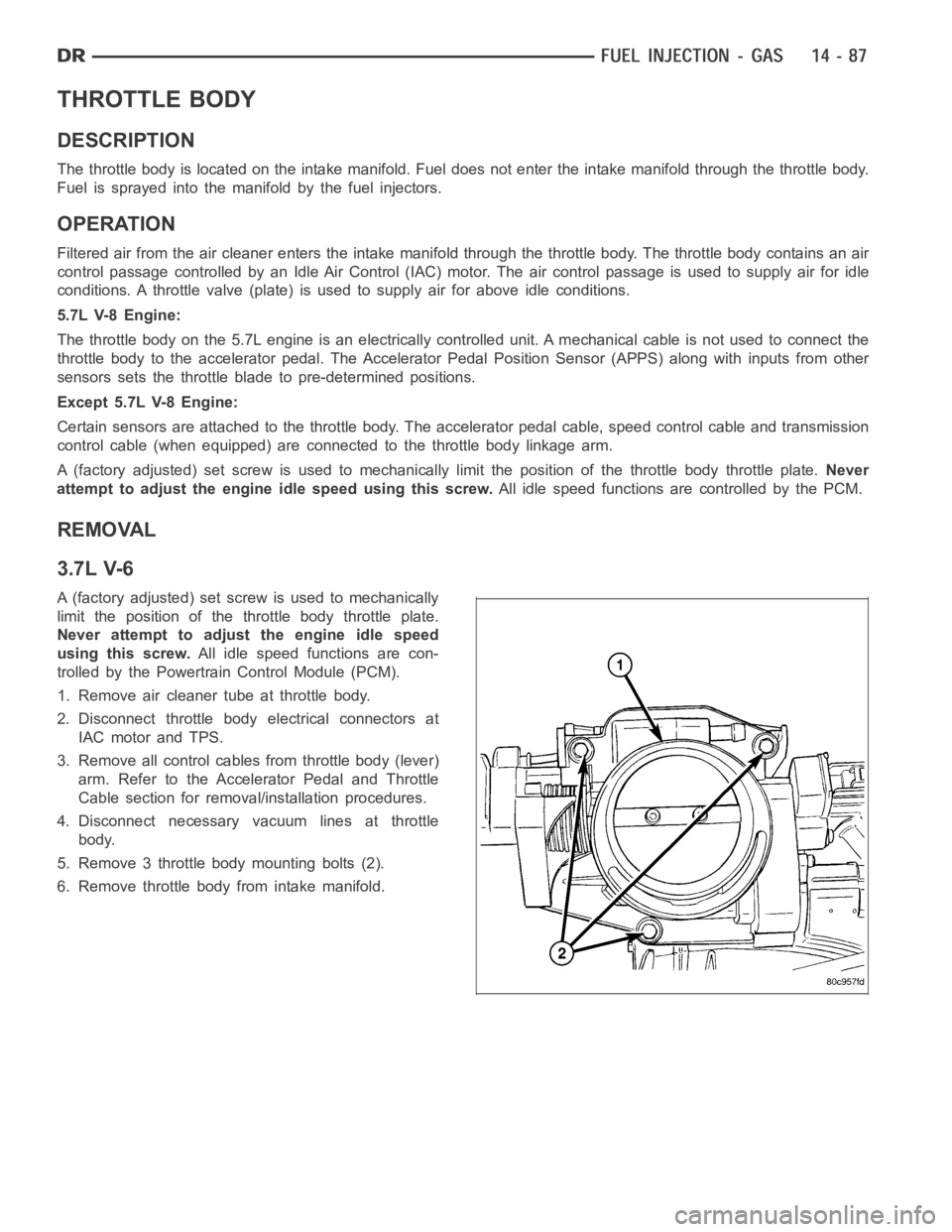
A (factory adjusted) set screw is used to mechanically
limit the position of the throttle body throttle plate.
Never attempt to adjust the engine idle speed
using this screw.All idle speed functions are con-
trolled by the Powertrain Control Module (PCM).
1. Remove air cleaner tube at throttle body.
2. Disconnect throttle body electrical connectors at
IAC motor and TPS.
3. Remove all control cables from throttle body (lever)
arm. Refer to the Accelerator Pedal and Throttle
Cable section for removal/installation procedures.
4. Disconnect necessary vacuum lines at throttle
body.
5. Remove 3 throttle body mounting bolts (2).
6. Remove throttle body from intake manifold.
Page 2325 of 5267
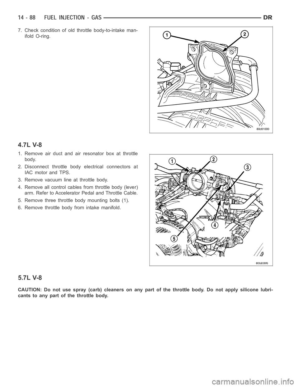
7. Check condition of old throttle body-to-intake man-
ifold O-ring.
4.7L V-8
1. Remove air duct and air resonator box at throttle
body.
2. Disconnect throttle body electrical connectors at
IAC motor and TPS.
3. Remove vacuum line at throttle body.
4. Remove all control cables from throttle body (lever)
arm. Refer to Accelerator Pedal and Throttle Cable.
5. Remove three throttle body mounting bolts (1).
6. Remove throttle body from intake manifold.
5.7L V-8
CAUTION: Do not use spray (carb) cleaners on any part of the throttle body. Do not apply silicone lubri-
cants to any part of the throttle body.
Page 2326 of 5267
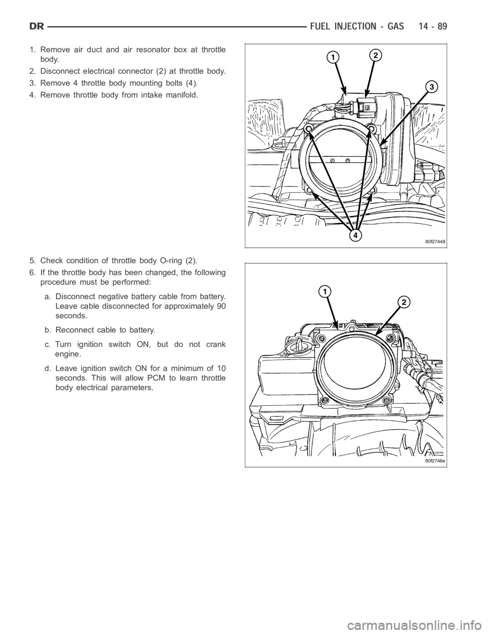
1. Remove air duct and air resonator box at throttle
body.
2. Disconnect electrical connector (2) at throttle body.
3. Remove 4 throttle body mounting bolts (4).
4. Remove throttle body from intake manifold.
5. Check condition of throttle body O-ring (2).
6. If the throttle body has been changed, the following
procedure must be performed:
a. Disconnect negative battery cable from battery.
Leave cable disconnected for approximately 90
seconds.
b. Reconnect cable to battery.
c. Turn ignition switch ON, but do not crank
engine.
d. Leave ignition switch ON for a minimum of 10
seconds. This will allow PCM to learn throttle
body electrical parameters.
Page 2329 of 5267
INSTALLATION
3.7L V-6
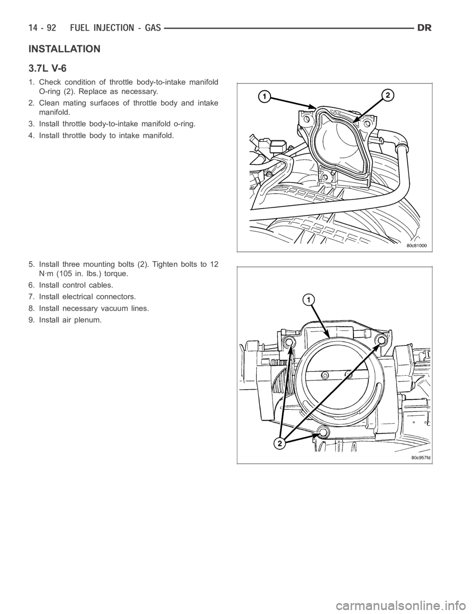
1. Check condition of throttle body-to-intake manifold
O-ring (2). Replace as necessary.
2. Clean mating surfaces of throttle body and intake
manifold.
3. Install throttle body-to-intake manifold o-ring.
4. Install throttle body to intake manifold.
5. Install three mounting bolts (2). Tighten bolts to 12
Nꞏm (105 in. lbs.) torque.
6. Install control cables.
7. Install electrical connectors.
8. Install necessary vacuum lines.
9. Install air plenum.
Page 2330 of 5267
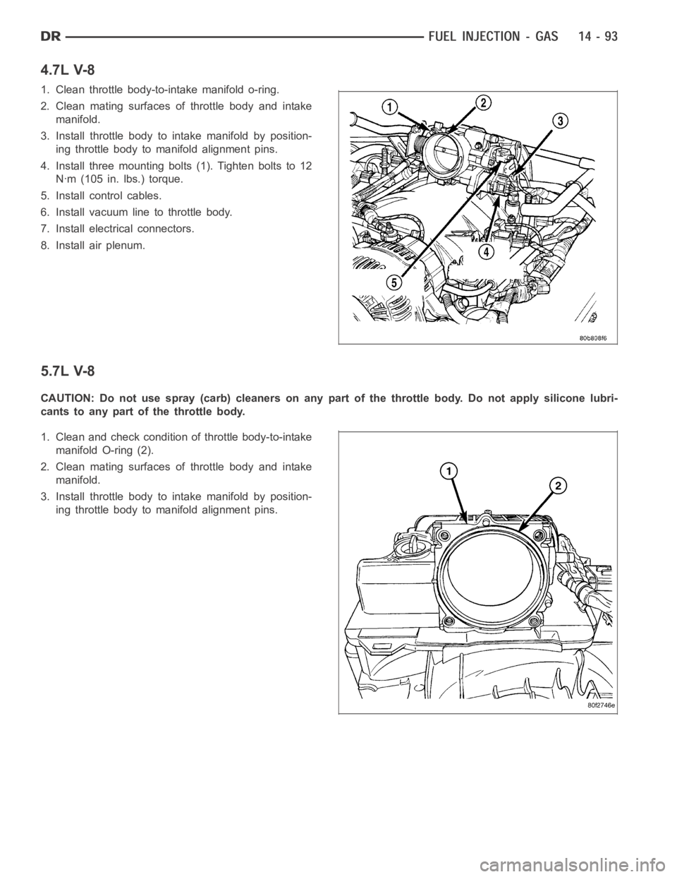
4.7L V-8
1. Clean throttle body-to-intake manifold o-ring.
2. Clean mating surfaces of throttle body and intake
manifold.
3. Install throttle body to intake manifold by position-
ing throttle body to manifold alignment pins.
4. Install three mounting bolts (1). Tighten bolts to 12
Nꞏm (105 in. lbs.) torque.
5. Install control cables.
6. Install vacuum line to throttle body.
7. Install electrical connectors.
8. Install air plenum.
5.7L V-8
CAUTION: Do not use spray (carb) cleaners on any part of the throttle body. Do not apply silicone lubri-
cants to any part of the throttle body.
1. Clean and check condition of throttle body-to-intake
manifold O-ring (2).
2. Clean mating surfaces of throttle body and intake
manifold.
3. Install throttle body to intake manifold by position-
ing throttle body to manifold alignment pins.
Page 2336 of 5267
OPERATION
The 5.7L V-8 engine does not use a separate Throttle Position Sensor (TPS) on the throttle body.
The 3-wire TPS provides the Powertrain Control Module (PCM) with an input signal (voltage) that represents the
throttle blade position of the throttle body. The sensor is connected to the throttle blade shaft. As the position of the
throttle blade changes, the output voltage of the TPS changes.
The PCM supplies approximately 5 volts to the TPS. The TPS output voltage (input signal to the PCM) represents
the throttle blade position. The PCM receives an input signal voltage fromthe TPS. This will vary in an approximate
range of from .26 volts at minimum throttle opening (idle), to 4.49 volts atwide open throttle. Along with inputs from
other sensors, the PCM uses the TPS input to determine current engine operating conditions. In response to engine
operating conditions, the PCM will adjust fuel injector pulse width and ignition timing.
The PCM needs to identify the actions and position of the throttle blade at all times. This information is needed to
assist in performing the following calculations:
Ignition timing advance
Fuel injection pulse-width
Idle (learned value or minimum TPS)
Off-idle (0.06 volt)
Wide Open Throttle (WOT) open loop (2.608 volts above learned idle voltage)
Deceleration fuel lean out
Fuel cutoff during cranking at WOT (2.608 volts above learned idle voltage)
A/C WOT cutoff (certain automatic transmissions only)
REMOVAL
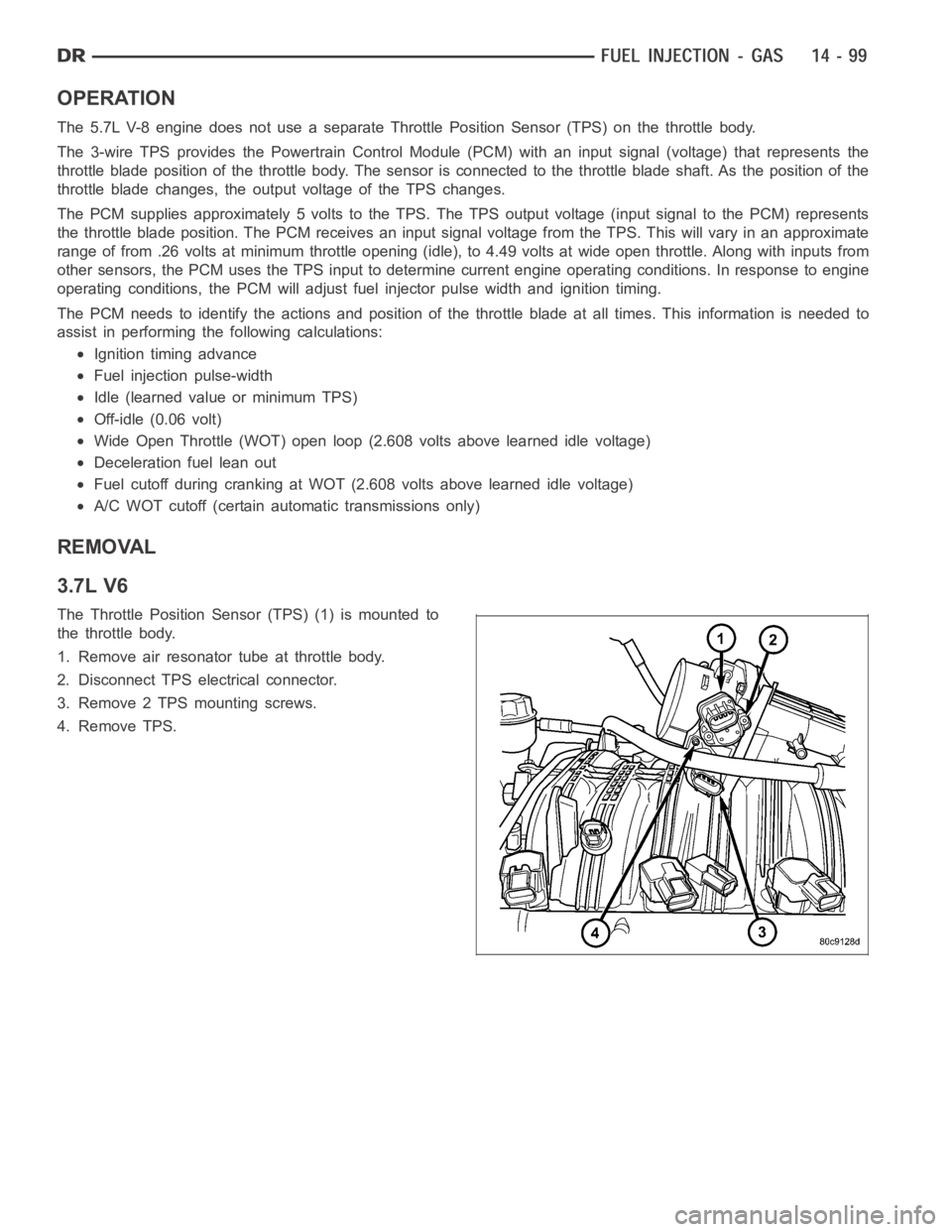
3.7L V6
The Throttle Position Sensor (TPS) (1) is mounted to
the throttle body.
1. Remove air resonator tube at throttle body.
2. Disconnect TPS electrical connector.
3. Remove 2 TPS mounting screws.
4. Remove TPS.
Page 2343 of 5267
Fuel enters the system from the electric fuel transfer (lift) pump, which is located inside of the fuel tank and attached
to the fuel tank module (the fuel transfer pump is no longer attached to the engine). Fuel is forced through the fuel
filter element and then enters the Fuel Pump/Gear Pump, which is attached to the rear of the fuel injection pump.
The Fuel Pump/Gear Pump is a low-pressure pump and produce pressures ranging from 551.5 kpa (80 psi) to 1241
kpa (180) psi. Fuel then enters the fuel injection pump. Low pressure fuel is then supplied to the FCA (Fuel Control
Actuator).
The FCA is an electronically controlled solenoid valve. The ECM controls the amount of fuel that enters the high-
pressure pumping chambers by opening and closing the FCA based on a demanded fuel pressure. The FPS (Fuel
Pressure Sensor) on the fuel rail monitors the actual fuel pressure and provides it as an input to the ECM. When
the actuator is opened, the maximum amount of fuel is being supplied to the fuel injection pump. Any fuel that does
not enter the injection pump is directed to the overflow valve. The overflow valve regulates how much excess fuel
is used for lubrication of the pump and how much is returned to the tank through the drain manifold.
Fuel entering the injection pump is pressurized to between 300-1600 bar (4351-23,206 psi) by three radial pumping
chambers. The pressurized fuel is then supplied to the fuel rail.
STANDARD PROCEDURE
WATER DRAINING AT FUEL FILTER
Refer to Fuel Filter/Water Separatorremoval/installation for procedures.
CLEANING FUEL SYSTEM PARTS
CAUTION: Cleanliness cannot be overemphasized when handling or replacingdieselfuelsystemcompo-
nents. This especially includes the fuel injectors, high-pressure fuel lines and fuel injection pump. Very tight
tolerances are used with these parts. Dirt contamination could cause rapid part wear and possible plugging
of fuel injector nozzle tip holes. This in turn could lead to possible engine misfire. Always wash/clean any
fuel system component thoroughly before disassembly and then air dry. Capor cover any open part after
disassembly. Before assembly, examine each part for dirt, grease or othercontaminants and clean if nec-
essary. When installing new parts, lubricate them with clean engine oil orclean diesel fuel only.
FUEL SYSTEM PRIMING
A certain amount of air becomes trappedin the fuel system when fuel system components on the supply and/or
high-pressure side are serviced or replaced. Fuel system priming is accomplished using the electric fuel transfer (lift)
pump.
Servicing or replacing fuel system components will not require fuel systempriming.
The fuel transfer (lift) pump is self-priming: When the key is first turnedon (without cranking engine), the pump
operates for approximately 1 to 2 second and then shuts off (Note: When ambient temperatures are cold enough to
cause the intake air heaters to operate, the fuel lift pump will operate during the entire intake air pre-heat cycle).
The pump will also operate for up to 25 seconds after the starter is quickly engaged, and then disengaged without
allowing the engine to start. The pump shuts off immediately if the key is onand the engine stops running.
1. Turn key to CRANK position and quickly release key to ON position before engine starts. This will operate fuel
transfer pump for approximately 25 seconds.
2. Crank engine. If the engine does not start after 25 seconds, turn key to OFF position, and leave it off for at least
5 seconds. Repeat previous step until engine starts.
3. Fuel system priming is now completed.
4. Attempt to start engine. If engine will not start, proceed to following steps.When engine does start, it may run
erratically and be noisy for a few minutes. This is a normal condition.
CAUTION: Do not engage the starter motor for more than 30 seconds at a time. Allow two minutes between
cranking intervals.
5. Perform previous fuel priming procedure steps using fuel transfer pump. Be sure fuel is present at fuel tank.
6. Crank the engine for 30 seconds at a time to allow fuel system to prime.
Page 2386 of 5267
OPERATION
High-pressure fuel is supplied from the injection pump, through a high-pressure fuel line, into a fuel rail, through
high-pressure lines, through steel connectors and into the solenoid actuated fuel injector. The ECM actuates the
solenoid causing the needle valve to rise and fuel flows through the spray holes in the nozzle tip into the combus-
tion chamber.
Each fuel injector is connected to the fuel rail by a high-pressure fuel line and a steel connector. This steel con-
nector is positioned into the cylinder head and sealed with an O-ring. The connector is retained in the cylinder head
by a nut (fitting) that is threaded into the cylinder head.
The torquing force of this threaded nut (fitting) provides a sealing pressure between the fuel line connector and the
fuel injector.Retaining nut torque is very critical.If the nut (fitting) is under torqued, the mating surfaces will not
seal and a high-pressure fuel leak will result. If the fitting is over torqued, the connector and injector will deform and
also cause a high-pressure fuel leak. This leak will be inside the cylinderhead and will not be visible. The result will
be a possible fuel injector miss-fire and low power, or a no-start condition.
The fuel injectors use hole type nozzles. High-pressure flows into the side of the injector, the ECM activates the
solenoid causing the injector needle to lift and fuel to be injected. The clearances in the nozzle bore are extremely
small and any dirt or contaminants will cause the injector to stick. Because of this, it is very important to do a
thorough cleaning of any lines before opening up any fuel system component. Always cover or cap any open fuel
connections before a fuel system repair is performed.
Each fuel injector connector tube contains an edge filter that is designedto break up small contaminants before
entering the fuel injector.The edge filters are not a substitute for proper cleaning and covering of allfuel
system components during repair.
The bottom of each fuel injector is sealed to the cylinder head with a1.5mmthick copper shim (gasket). The correct
thickness shim must always be re-installed after removing an injector.
Fuel pressure in the injector circuit decreases after injection. The injector needle valve is immediately closed and
fuel flow into the combustion chamber is stopped. Exhaust gases are prevented from entering the injector nozzle by
the needle valve.
REMOVAL
CAUTION: Refer to Cleaning Fuel System Parts.
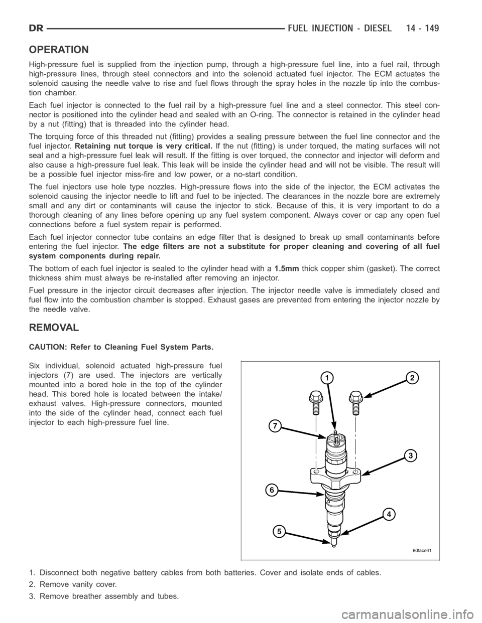
Six individual, solenoid actuated high-pressure fuel
injectors (7) are used. The injectors are vertically
mounted into a bored hole in the top of the cylinder
head. This bored hole is located between the intake/
exhaust valves. High-pressure connectors, mounted
into the side of the cylinder head, connect each fuel
injector to each high-pressure fuel line.
1. Disconnect both negative battery cables from both batteries. Cover andisolate ends of cables.
2. Remove vanity cover.
3. Remove breather assembly and tubes.