2006 DODGE RAM SRT-10 air condition
[x] Cancel search: air conditionPage 2140 of 5267
DIESEL ENGINE
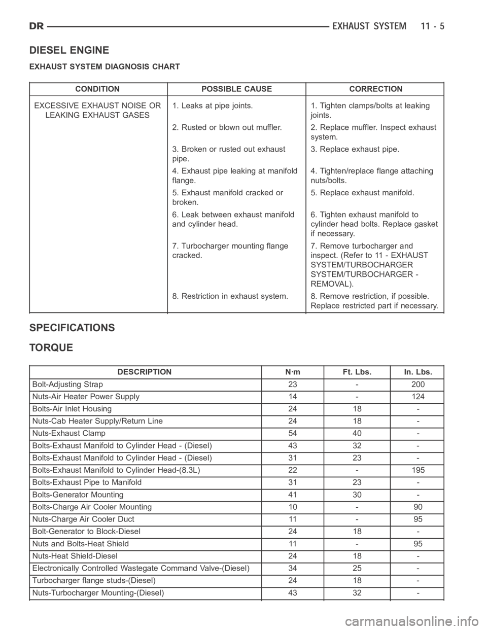
EXHAUST SYSTEM DIAGNOSIS CHART
CONDITION POSSIBLE CAUSE CORRECTION
EXCESSIVE EXHAUST NOISE OR
LEAKING EXHAUST GASES1. Leaks at pipe joints. 1. Tighten clamps/bolts at leaking
joints.
2. Rusted or blown out muffler. 2. Replace muffler. Inspect exhaust
system.
3. Broken or rusted out exhaust
pipe.3. Replace exhaust pipe.
4. Exhaust pipe leaking at manifold
flange.4. Tighten/replace flange attaching
nuts/bolts.
5. Exhaust manifold cracked or
broken.5. Replace exhaust manifold.
6. Leak between exhaust manifold
and cylinder head.6. Tighten exhaust manifold to
cylinder head bolts. Replace gasket
if necessary.
7. Turbocharger mounting flange
cracked.7. Remove turbocharger and
inspect. (Refer to 11 - EXHAUST
SYSTEM/TURBOCHARGER
SYSTEM/TURBOCHARGER -
REMOVAL).
8. Restriction in exhaust system. 8. Remove restriction, if possible.
Replace restricted part if necessary.
SPECIFICATIONS
TORQUE
DESCRIPTION Nꞏm Ft. Lbs. In. Lbs.
Bolt-Adjusting Strap 23 - 200
Nuts-Air Heater Power Supply 14 - 124
Bolts-Air Inlet Housing 24 18 -
Nuts-Cab Heater Supply/Return Line 24 18 -
Nuts-Exhaust Clamp 54 40 -
Bolts-Exhaust Manifold to Cylinder Head - (Diesel) 43 32 -
Bolts-Exhaust Manifold to Cylinder Head - (Diesel) 31 23 -
Bolts-Exhaust Manifold to Cylinder Head-(8.3L) 22 - 195
Bolts-Exhaust Pipe to Manifold 31 23 -
Bolts-Generator Mounting 41 30 -
Bolts-Charge Air Cooler Mounting 10 - 90
Nuts-Charge Air Cooler Duct 11 - 95
Bolt-Generator to Block-Diesel 24 18 -
Nuts and Bolts-Heat Shield 11 - 95
Nuts-Heat Shield-Diesel 24 18 -
Electronically Controlled Wastegate Command Valve-(Diesel) 34 25 -
Turbocharger flange studs-(Diesel) 24 18 -
Nuts-Turbocharger Mounting-(Diesel) 43 32 -
Page 2162 of 5267
OPERATION
Exhaust gas pressure and energy drive the turbine,
which in turn drives a centrifugal compressor that
compresses the inlet air, and forces the air into the
engine through the charge air cooler and plumbing.
Since heat is a by-product of this compression, the air
must pass through a charge air cooler to cool the
incoming air and maintain power and efficiency.
Increasing air flow to the engine provides:
Improved engine performance
Lower exhaust smoke density
Improved operating economy
Altitude compensation
Noise reduction.
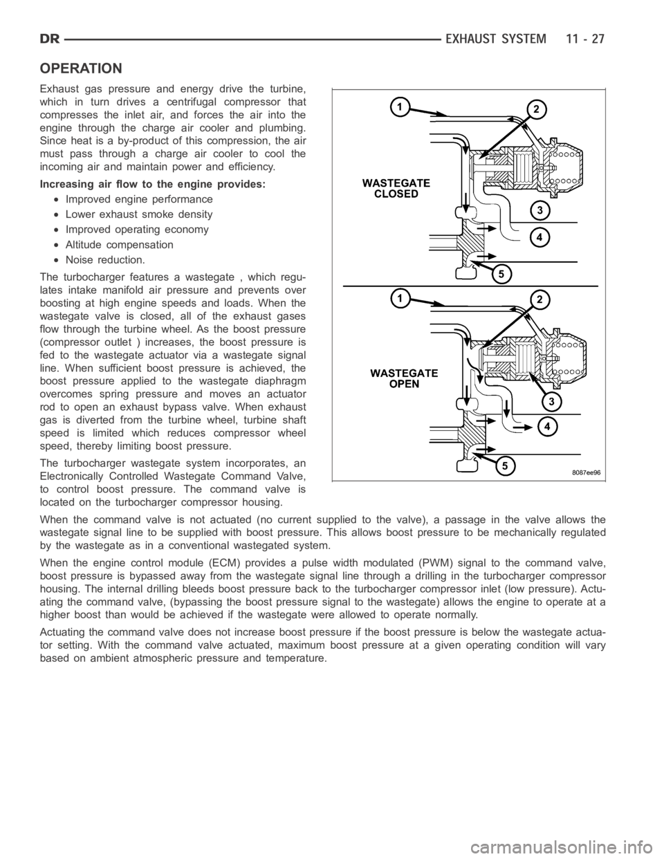
The turbocharger features a wastegate , which regu-
lates intake manifold air pressure and prevents over
boosting at high engine speeds and loads. When the
wastegate valve is closed, all of the exhaust gases
flow through the turbine wheel. As the boost pressure
(compressor outlet ) increases, the boost pressure is
fed to the wastegate actuator via a wastegate signal
line. When sufficient boost pressure is achieved, the
boost pressure applied to the wastegate diaphragm
overcomes spring pressure and moves an actuator
rod to open an exhaust bypass valve. When exhaust
gas is diverted from the turbine wheel, turbine shaft
speed is limited which reduces compressor wheel
speed, thereby limiting boost pressure.
The turbocharger wastegate system incorporates, an
Electronically Controlled Wastegate Command Valve,
to control boost pressure. The command valve is
located on the turbocharger compressor housing.
When the command valve is not actuated (no current supplied to the valve), apassage in the valve allows the
wastegate signal line to be supplied with boost pressure. This allows boost pressure to be mechanically regulated
by the wastegate as in a conventional wastegated system.
When the engine control module (ECM) provides a pulse width modulated (PWM) signal to the command valve,
boost pressure is bypassed away from the wastegate signal line through a drilling in the turbocharger compressor
housing. The internal drilling bleeds boost pressure back to the turbocharger compressor inlet (low pressure). Actu-
ating the command valve, (bypassing the boost pressure signal to the wastegate) allows the engine to operate at a
higher boost than would be achieved if the wastegate were allowed to operate normally.
Actuating the command valve does not increase boost pressure if the boost pressure is below the wastegate actua-
tor setting. With the command valve actuated, maximum boost pressure at a given operating condition will vary
based on ambient atmospheric pressure and temperature.
Page 2165 of 5267
TURBOCHARGER OIL DRAIN TUBE
NOTE: If oil is present on either the inlet or
exhaust side of the turbo charger, check the
charge air cooler for evidence of oil. Clean charge
air cooler of any oil before starting the engine.
Failure to do this can result in severe engine dam-
age.
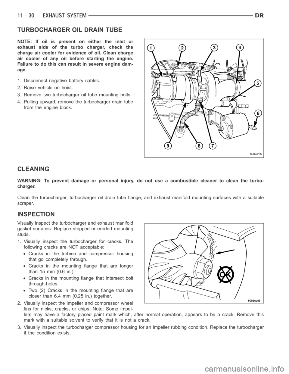
1. Disconnect negative battery cables.
2. Raise vehicle on hoist.
3. Remove two turbocharger oil tube mounting bolts
4. Pulling upward, remove the turbocharger drain tube
from the engine block.
CLEANING
WARNING: To prevent damage or personal injury, do not use a combustible cleaner to clean the turbo-
charger.
Clean the turbocharger, turbocharger oil drain tube flange, and exhaust manifold mounting surfaces with a suitable
scraper.
INSPECTION
Visually inspect the turbocharger and exhaust manifold
gasket surfaces. Replace stripped or eroded mounting
studs.
1. Visually inspect the turbocharger for cracks. The
following cracks are NOT acceptable:
Cracks in the turbine and compressor housing
that go completely through.
Cracks in the mounting flange that are longer
than 15 mm (0.6 in.).
Cracks in the mounting flange that intersect bolt
through-holes.
Two (2) Cracks in the mounting flange that are
closer than 6.4 mm (0.25 in.) together.
2. Visually inspect the impeller and compressor wheel
fins for nicks, cracks, or chips. Note: Some impel-
lers may have a factory placed paint mark which, after normal operation, appears to be a crack. Remove this
mark with a suitable solvent to verify that it is not a crack.
3. Visually inspect the turbocharger compressor housing for an impeller rubbing condition. Replace the turbocharger
if the condition exists.
Page 2170 of 5267
DIAGNOSIS AND TESTING
CHARGE AIR COOLER SYSTEM - LEAKS
Low turbocharger boost pressure and low engine per-
formance can be caused by leaks in the charge air
cooler or plumbing. Fuel staining on the exhaust man-
ifold can also be an indication that there are leaks in
the air system. The followingprocedure outlines how
to check for leaks in the charge air cooler system.
This procedure can also be used to check for leaks in
the wastegate signal line or the wastegate canister.
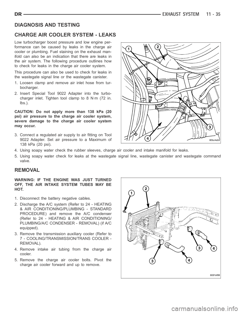
1. Loosen clamp and remove air inlet hose from tur-
bocharger.
2. Insert Special Tool 9022 Adapter into the turbo-
charger inlet. Tighten tool clamp to 8 Nꞏm (72 in.
lbs.).
CAUTION: Do not apply more than 138 kPa (20
psi) air pressure to the charge air cooler system,
severe damage to the charge air cooler system
may occur.
3. Connect a regulated air supply to air fitting on Tool
9022 Adapter. Set air pressure to a Maximum of
138 kPa (20 psi).
4. Using soapy water check the rubber sleeves, charge air cooler and intakemanifold for leaks.
5. Using soapy water check for leaks at the wastegate signal line, wastegate canister and wastegate command
valve.
REMOVAL
WARNING: IF THE ENGINE WAS JUST TURNED
OFF, THE AIR INTAKE SYSTEM TUBES MAY BE
HOT.
1. Disconnect the battery negative cables.
2. Discharge the A/C system (Refer to 24 - HEATING
& AIR CONDITIONING/PLUMBING - STANDARD
PROCEDURE) and remove the A/C condenser
(Refer to 24 - HEATING & AIR CONDITIONING/
PLUMBING/A/C CONDENSER - REMOVAL) (if A/C
equipped).
3. Remove the transmission auxiliary cooler (Refer to
7 - COOLING/TRANSMISSION/TRANS COOLER -
REMOVAL).
4. Remove intake air tubing from the charge air
cooler.
5. Remove the charge air cooler bolts. Pivot the
charge air cooler forward and up to remove.
Page 2172 of 5267
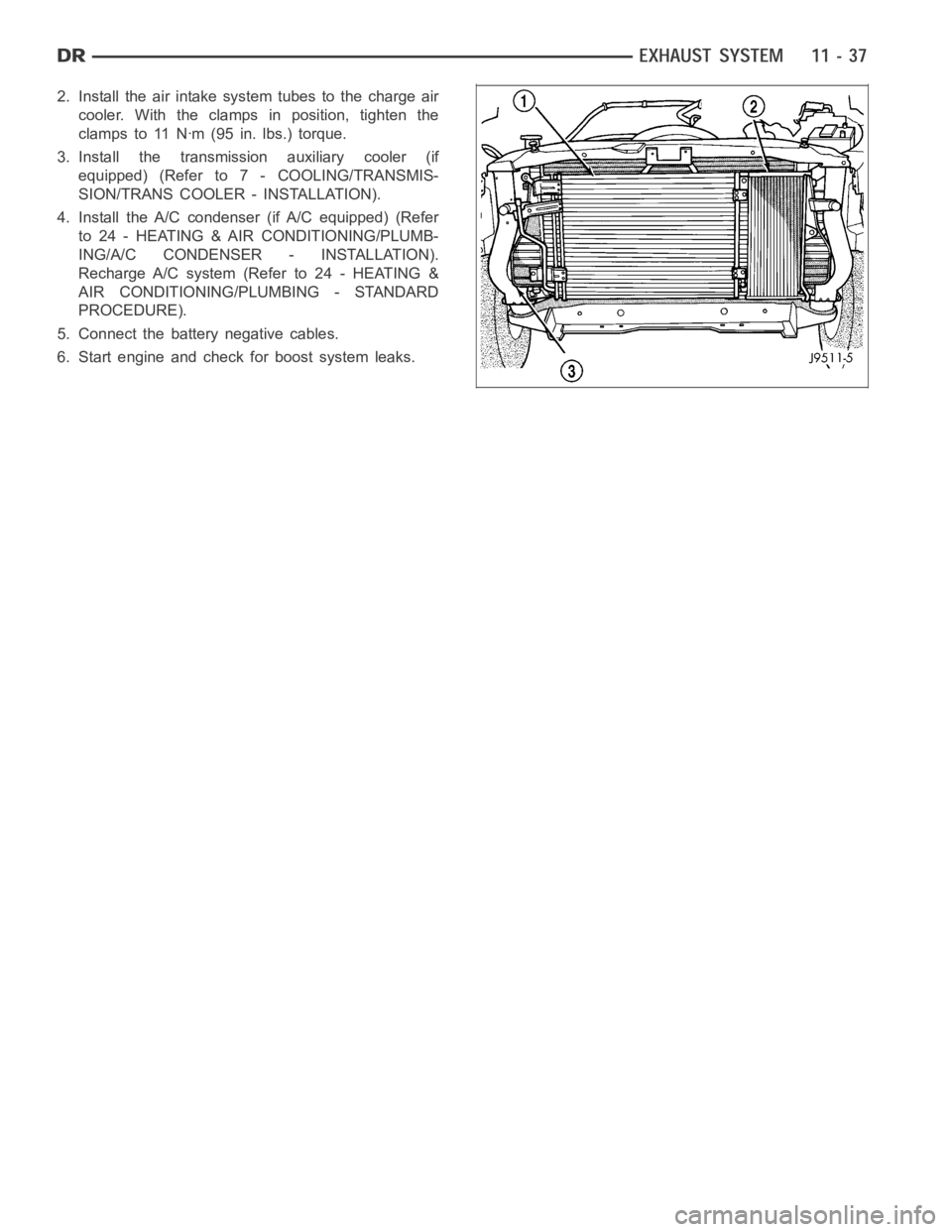
2. Install the air intake system tubes to the charge air
cooler. With the clamps in position, tighten the
clamps to 11 Nꞏm (95 in. lbs.) torque.
3. Install the transmission auxiliary cooler (if
equipped) (Refer to 7 - COOLING/TRANSMIS-
SION/TRANS COOLER - INSTALLATION).
4. Install the A/C condenser (if A/C equipped) (Refer
to 24 - HEATING & AIR CONDITIONING/PLUMB-
ING/A/C CONDENSER - INSTALLATION).
Recharge A/C system (Refer to 24 - HEATING &
AIR CONDITIONING/PLUMBING - STANDARD
PROCEDURE).
5. Connect the battery negative cables.
6. Start engine and check for boost system leaks.
Page 2190 of 5267
FRAME
WARNING
WARNINGS
Use eye protection when grinding or welding metal. Failure to do this couldresult in serious personal injury
or death.
Before proceeding with frame repair involving grinding or welding, verify that the vehicle fuel system is not
leaking or in contact with the repair area. Failure to do this could result in serious personal injury or death.
Do not allow an open flame or heat and metal spatter from arc welding to contact plastic body panels. Fire,
explosion can result causing serious personal injury or death.
When welded frame components are replaced, ensure that a complete penetration weld is achieved during
installation. If not, dangerous operating conditions can result.
Stand clear of cables or chains on pulling equipment during frame straightening operations. Failure to do
this can result in serious personal injury or death.
Do not venture under a hoisted vehicle that is not supported on safety stands. Walking under an unsup-
ported vehicle can result in serious personal injury or death.
1500 series Dodge Ram Trucks (2002 and later) are not designed for snow plowequipment. The front col-
lision repair tips must not be installed on any truck equipped with a snow plow, or even intended to be
equipped with a snow plow.
Do not reuse damaged fasteners. The quality of repair would be suspect. Failure to use only production
fasteners or fasteners of equivalent hardness can result in loosening or failure of the part. Do not drill any
holes in the frame that are not specifically outlined in this, or in other DaimlerChrysler procedures as frame
rail failure can result causing serious personal injury or death. When using heat to straighten frame com-
ponents, do not exceed 566°C (1050°F). If temperature is exceeded, metal fatigue can happen and result in
serious personal injury or death.
Page 2192 of 5267
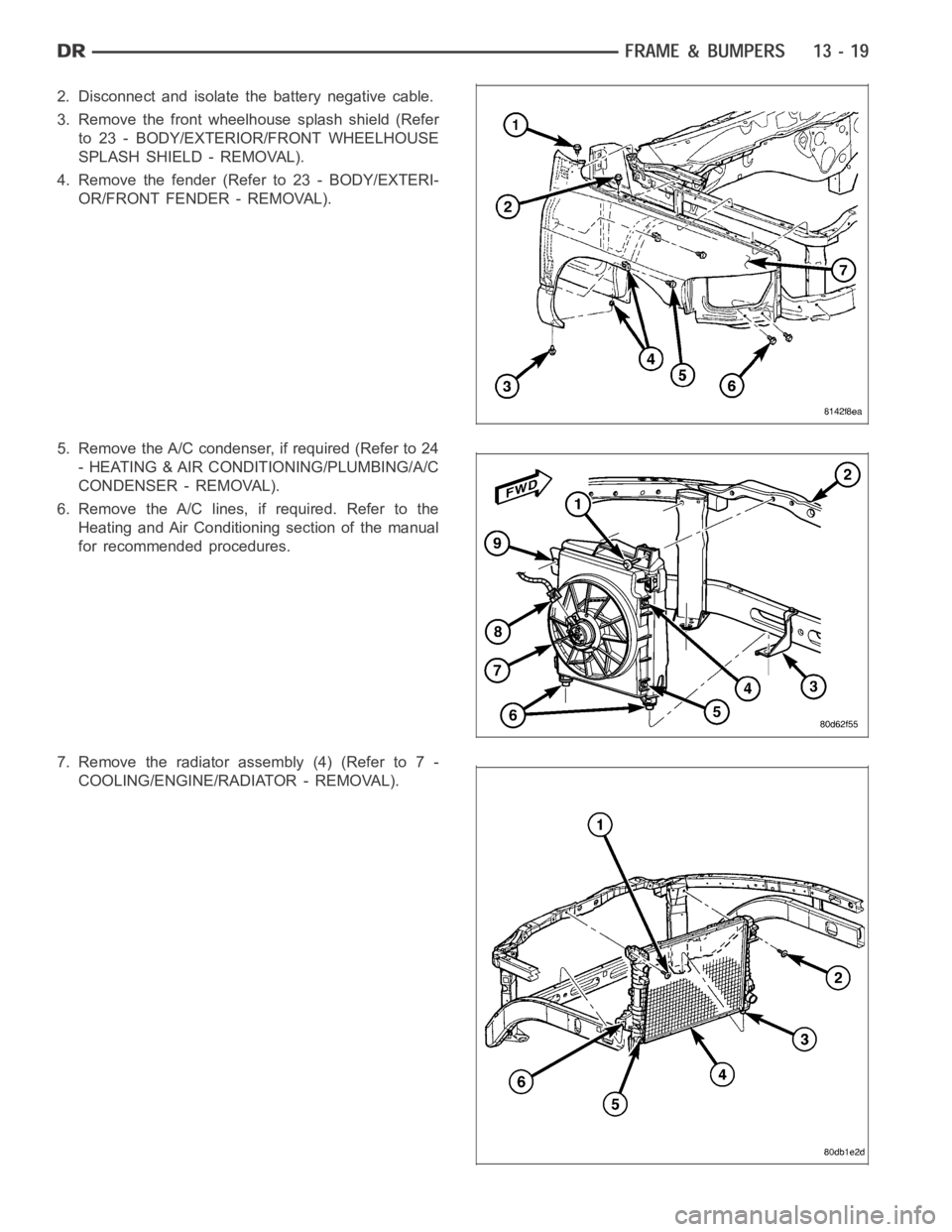
2. Disconnect and isolate the battery negative cable.
3. Remove the front wheelhouse splash shield (Refer
to 23 - BODY/EXTERIOR/FRONT WHEELHOUSE
SPLASH SHIELD - REMOVAL).
4. Remove the fender (Refer to 23 - BODY/EXTERI-
OR/FRONT FENDER - REMOVAL).
5. Remove the A/C condenser, if required (Refer to 24
- HEATING & AIR CONDITIONING/PLUMBING/A/C
CONDENSER - REMOVAL).
6. Remove the A/C lines, if required. Refer to the
Heating and Air Conditioning section of the manual
for recommended procedures.
7. Remove the radiator assembly (4) (Refer to 7 -
COOLING/ENGINE/RADIATOR - REMOVAL).
Page 2200 of 5267
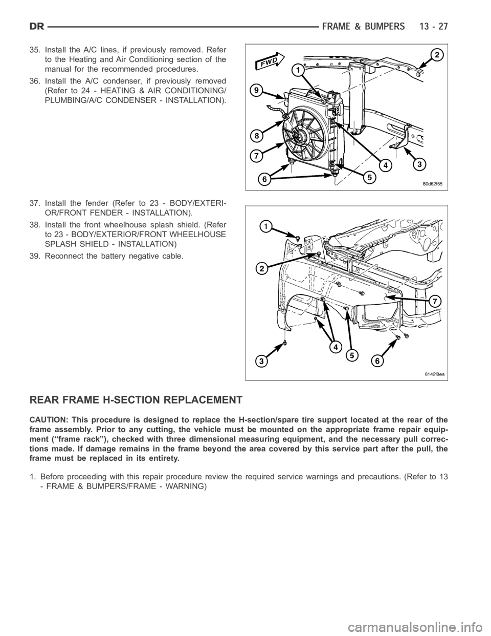
35. Install the A/C lines, if previously removed. Refer
to the Heating and Air Conditioning section of the
manual for the recommended procedures.
36. Install the A/C condenser, if previously removed
(Refer to 24 - HEATING & AIR CONDITIONING/
PLUMBING/A/C CONDENSER - INSTALLATION).
37. Install the fender (Refer to 23 - BODY/EXTERI-
OR/FRONT FENDER - INSTALLATION).
38. Install the front wheelhouse splash shield. (Refer
to 23 - BODY/EXTERIOR/FRONT WHEELHOUSE
SPLASH SHIELD - INSTALLATION)
39. Reconnect the battery negative cable.
REAR FRAME H-SECTION REPLACEMENT
CAUTION: This procedure is designed to replace the H-section/spare tire support located at the rear of the
frame assembly. Prior to any cutting, the vehicle must be mounted on the appropriate frame repair equip-
ment (“frame rack”), checked with three dimensional measuring equipment, and the necessary pull correc-
tions made. If damage remains in the frame beyond the area covered by this service part after the pull, the
frame must be replaced in its entirety.
1. Before proceeding with this repair procedure review the required service warnings and precautions. (Refer to 13
- FRAME & BUMPERS/FRAME - WARNING)