Page 2298 of 5267

RELAY - FUEL PUMP
DESCRIPTION
The 5–pin, 12–volt, fuel pump relay is located in the Power Distribution Center (PDC). Refer to the label on the PDC
cover for relay location.
OPERATION
The Powertrain Control Module (PCM) energizes the electric fuel pump through the fuel pump relay. The fuel pump
relay is energized by first applying battery voltage to it when the ignition key is turned ON, and then applying a
ground signal to the relay from the PCM.
Whenever the ignition key is turned ON, the electric fuel pump will operate. But, the PCM will shut-down the ground
circuit to the fuel pump relay in approximately 1–3 seconds unless the engine is operating or the starter motor is
engaged.
REMOVAL
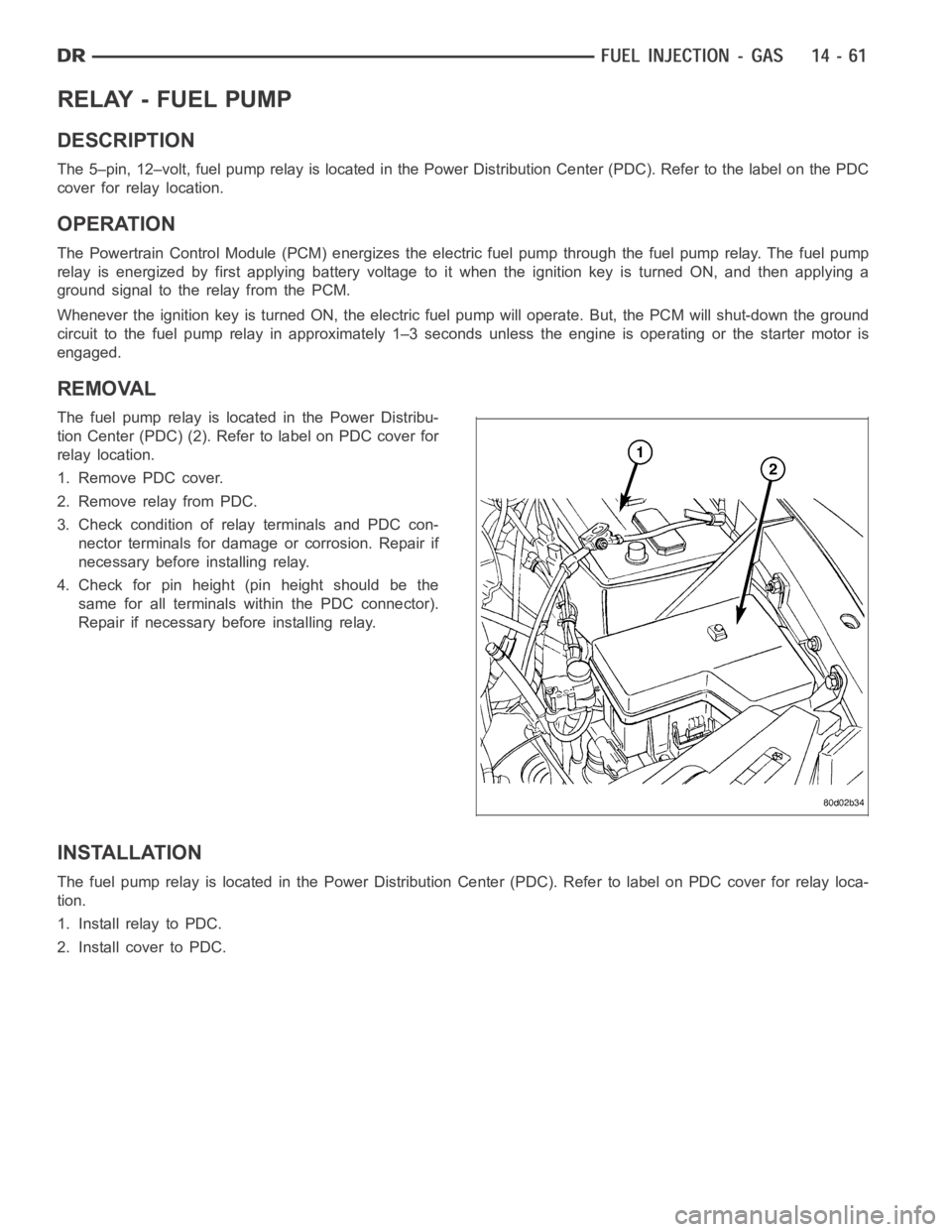
The fuel pump relay is located in the Power Distribu-
tion Center (PDC) (2). Refer to label on PDC cover for
relay location.
1. Remove PDC cover.
2. Remove relay from PDC.
3. Check condition of relay terminals and PDC con-
nector terminals for damage or corrosion. Repair if
necessary before installing relay.
4. Check for pin height (pin height should be the
same for all terminals within the PDC connector).
Repair if necessary before installing relay.
INSTALLATION
The fuel pump relay is located in the Power Distribution Center (PDC). Refer to label on PDC cover for relay loca-
tion.
1. Install relay to PDC.
2. Install cover to PDC.
Page 2301 of 5267

identical conditions, the PCM recalls that 125 steps were required to maintain the target. This program allows for
greater customer satisfaction due to greater control of engine idle.
Another function of the memory program, which occurs when the power steering switch (if equipped), or the A/C
request circuit, requires that the IAC stepper motor control engine rpm, is the recording of the last targeted steps
into the memory cell. The PCM can anticipate A/C compressor loads. This is accomplished by delaying compressor
operation for approximately 0.5 seconds until the PCM moves the IAC stepper motor to the recorded steps that
were loaded into the memory cell. Using this program helps eliminate idle-quality changes as loads change. Finally,
the PCM incorporates a
No-Loadengine speed limiter of approximately 1800 - 2000 rpm, when it recognizes that
the TPS is indicating an idle signal and IAC motor cannot maintain engine idle.
A (factory adjusted) set screw is usedto mechanically limit the position of the throttle body throttle plate.Never
attempt to adjust the engine idle speed using this screw.All idle speed functions are controlled by the IAC
motor through the PCM.
REMOVAL
3.7L V-6
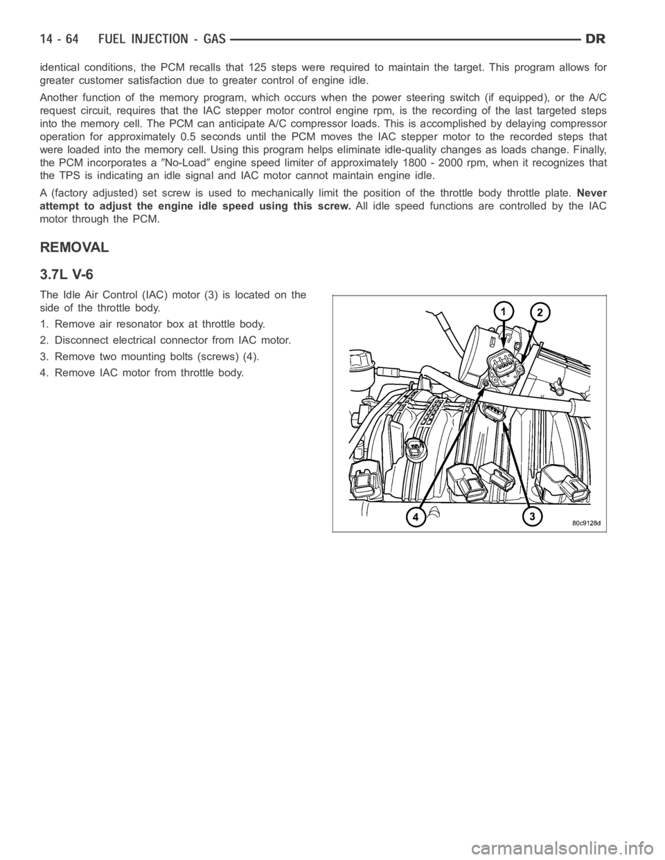
The Idle Air Control (IAC) motor (3) is located on the
side of the throttle body.
1. Remove air resonator box at throttle body.
2. Disconnect electrical connector from IAC motor.
3. Remove two mounting bolts (screws) (4).
4. Remove IAC motor from throttle body.
Page 2308 of 5267
REMOVAL
3.7L V-6
The intake manifold air temperature (IAT) sensor is
installed into the left side of intake manifold plenum.
1. Disconnect electrical connector from IAT sensor.
2. Clean dirt from intake manifold at sensor base.
3. Gently lift on small plastic release tab (3) and
rotate sensor about 1/4 turn counterclockwise for
removal.
4. Check condition of sensor O-ring.
Page 2309 of 5267
4.7L V-8
The intake manifold air temperature (IAT) sensor (3) is
installed into the left side of intake manifold plenum.
1. Disconnect electrical connector from IAT sensor.
2. Clean dirt from intake manifold at sensor base.
3. Gently lift on small plastic release tab (3) and
rotate sensor about 1/4 turn counterclockwise for
removal.
4. Check condition of sensor O-ring.
Page 2311 of 5267
3. Gently lift on small plastic release tab (3) and
rotate sensor about 1/4 turn counterclockwise for
removal.
4. Check condition of sensor O-ring.
INSTALLATION
3.7L V-6
The intake manifold air temperature (IAT) sensor (1) is
installed into the left side of intake manifold plenum.
1. Check condition of sensor O-ring.
2. Clean sensor mounting hole in intake manifold.
3. Position sensor into intake manifold and rotate
clockwise until past release tab (2).
4. Install electrical connector.
Page 2312 of 5267
4.7L V-8
The intake manifold air temperature (IAT) sensor (3) is
installed into the left side of intake manifold plenum.
1. Check condition of sensor O-ring.
2. Clean sensor mounting hole in intake manifold.
3. Position sensor into intake manifold and rotate
clockwise until past release tab.
4. Install electrical connector.
5.7L V-8
The intake manifold air temperature (IAT) sensor (2) is
installed into the front of the intake manifold air box
plenum.
1. Check condition of sensor O-ring.
2. Clean sensor mounting hole in intake manifold.
3. Position sensor into intake manifold and rotate
clockwise until past release tab.
4. Install electrical connector.
Page 2315 of 5267

higher altitude, because the air density changes with altitude. It will also help to correct for varying barometric pres-
sure. Barometric pressure and altitude have a direct inverse correlation; as altitude goes up, barometric goes down.
At key-on, the PCM powers up and looks at MAP voltage, and based upon the voltage it sees, it knows the current
barometric pressure (relative to altitude). Once the engine starts, the PCM looks at the voltage again, continuously
every 12 milliseconds, and compares the current voltage to what it was at key-on. The difference between current
voltage and what it was at key-on, is manifold vacuum.
During key-on (engine not running) the sensor reads (updates) barometricpressure. A normal range can be
obtained by monitoring a known good sensor.
As the altitude increases, the air becomes thinner (less oxygen). If a vehicleisstartedanddriventoaverydifferent
altitude than where it was at key-on, the barometric pressure needs to be updated. Any time the PCM sees Wide
Open Throttle (WOT), based upon Throttle Position Sensor (TPS) angle and RPM, it will update barometric pressure
in the MAP memory cell. With periodic updates, the PCM can make its calculations more effectively.
The PCM uses the MAP sensor input to aid in calculating the following:
Manifold pressure
Barometric pressure
Engine load
Injector pulse-width
Spark-advance programs
Shift-point strategies (certain automatic transmissions only)
Idle speed
Decel fuel shutoff
The MAP sensor signal is provided from asingle piezoresistive element located in the center of a diaphragm. The
element and diaphragm are both made ofsilicone. As manifold pressure changes, the diaphragm moves causing
the element to deflect, which stresses the silicone. When silicone is exposed to stress, its resistance changes. As
manifold vacuum increases, the MAP sensor input voltage decreases proportionally. The sensor also contains elec-
tronics that condition the signal and provide temperature compensation.
The PCM recognizes a decrease in manifold pressure by monitoring a decrease in voltage from the reading stored
in the barometric pressure memory cell. The MAP sensor is a linear sensor; meaning as pressure changes, voltage
changes proportionately. The range of voltage output from the sensor is usually between 4.6 volts at sea level to as
low as 0.3 volts at 26 in. of Hg. Barometric pressure is the pressure exertedby the atmosphere upon an object. At
sea level on a standard day, no storm, barometric pressure is approximately 29.92 in Hg. For every 100 feet of
altitude, barometric pressure drops 0.10 in. Hg. If a storm goes through, it can change barometric pressure from
what should be present for that altitude. You should know what the average pressure and corresponding barometric
pressure is for your area.
Page 2317 of 5267
4.7L V-8
The MAP sensor (3) is located on the front of the
intake manifold. An O-ring seals the sensor to the
intake manifold.
1. Disconnect electrical connector at sensor.
2. Clean area around MAP sensor.
3. Remove 2 sensor mounting bolts.
4. Remove MAP sensor from intake manifold.
5. Check condition of sensor O-ring.
5.7L V-8
The Manifold Absolute Pressure (MAP) sensor is
mounted to the front of the intake manifold air plenum
box.