2006 DODGE RAM SRT-10 air conditioning
[x] Cancel search: air conditioningPage 5062 of 5267
The blend door actuators are diagnosed using a scan tool (Refer to 24 - HEATING & AIR CONDITIONING - DIAG-
NOSIS AND TESTING and to 24 - HVAC Electrical Diagnostics for more information).
The blend door actuators cannot be adjusted or repaired and, if faulty or damaged, they must be replaced.
REMOVAL
WARNING: On vehicles equipped with airbags, disable the airbag system before attempting any steering
wheel, steering column, or instrument panel component diagnosis or service. Disconnect and isolate the
battery negative (ground) cable, then wait two minutes for the airbag system capacitor to discharge before
performing further diagnosis or service. This is the only sure way to disable the airbag system. Failure to
take the proper precautions could result in accidental airbag deploymentand possible personal injury or
death.
NOTE: The single zone heating-A/C system is equipped with a single blend door actuator. The dual zone
system has two blend door actuators, one for the driver side blend-air doorand one for the passenger side
blend-air door.
SINGLE ZONE/DUAL ZONE DRIVER SIDE
1. Disconnect and isolate the negative battery cable.
2. Remove the instrument panel from the vehicle
(Refer to 23 - BODY/INSTRUMENT PANEL/IN-
STRUMENT PANEL ASSEMBLY - REMOVAL).
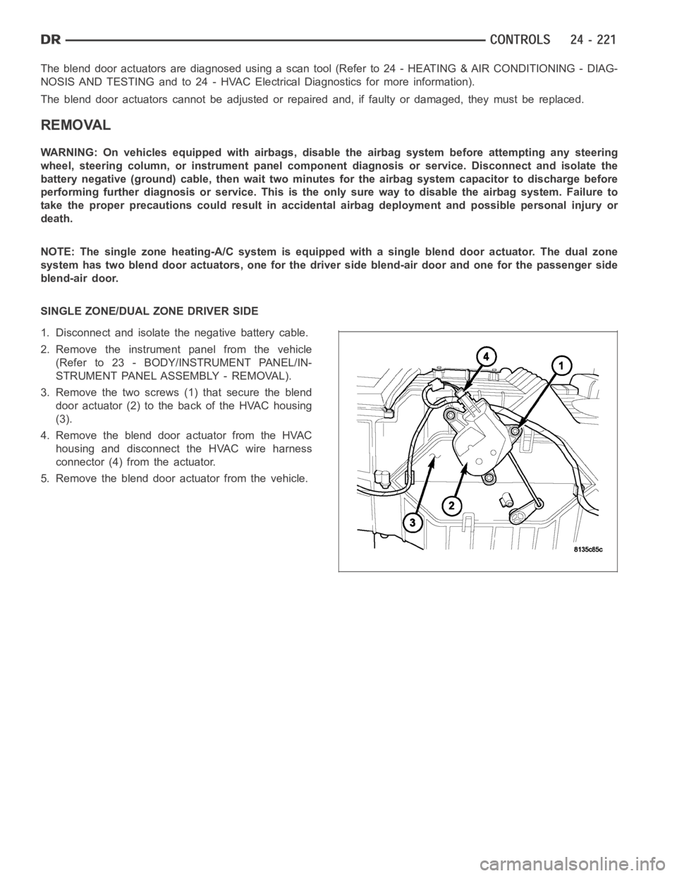
3. Remove the two screws (1) that secure the blend
door actuator (2) to the back of the HVAC housing
(3).
4. Remove the blend door actuator from the HVAC
housing and disconnect the HVAC wire harness
connector (4) from the actuator.
5. Remove the blend door actuator from the vehicle.
Page 5066 of 5267
ACTUATOR-MODE DOOR
DESCRIPTION
The mode door actuators are reversible, 12-volt direct
current (DC) servo motors.The heating-A/C systems
on this vehicle use two mode door actuators. One for
the panel/floor-air door and one for the defrost-air
door.
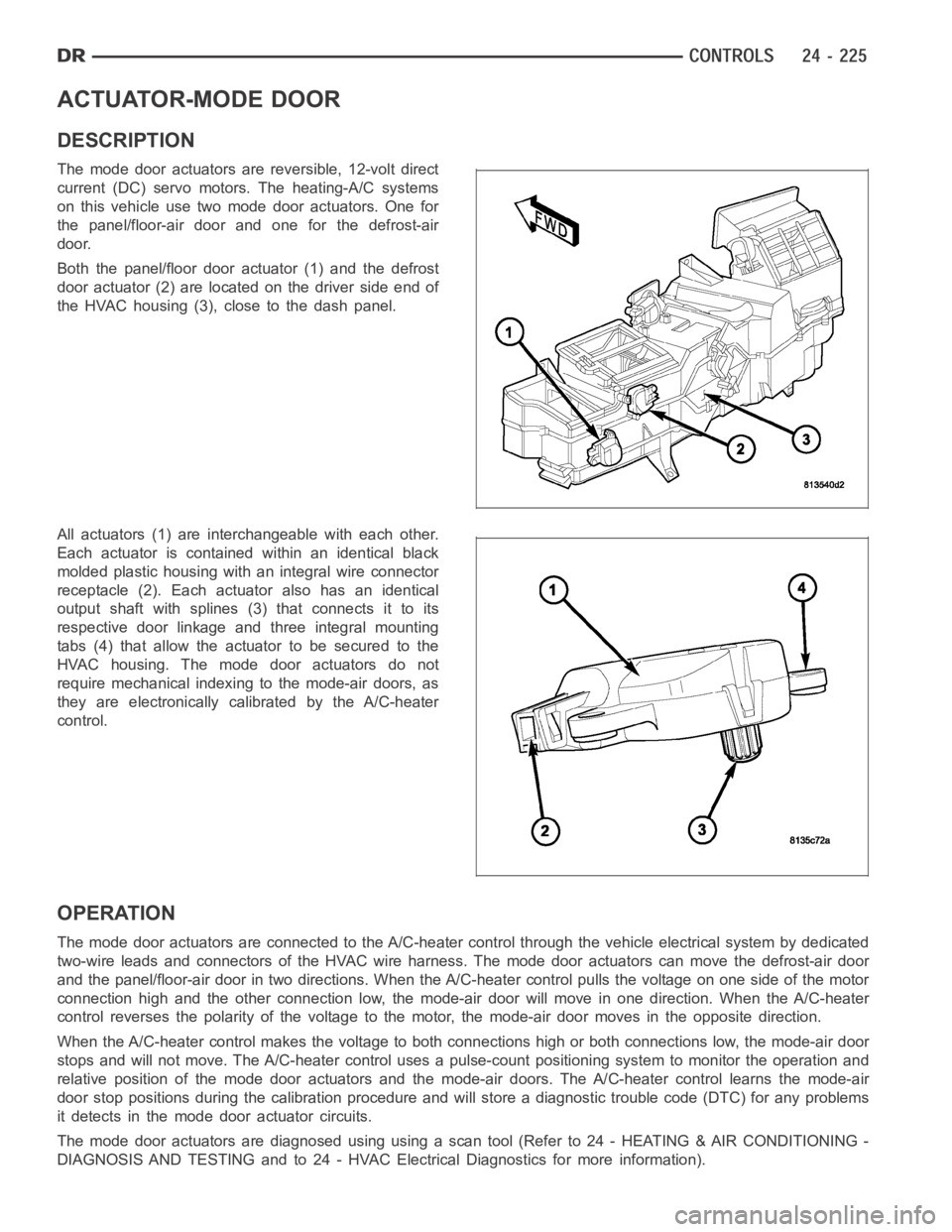
Both the panel/floor door actuator (1) and the defrost
door actuator (2) are located on the driver side end of
the HVAC housing (3), close to the dash panel.
All actuators (1) are interchangeable with each other.
Each actuator is contained within an identical black
molded plastic housing with an integral wire connector
receptacle (2). Each actuator also has an identical
output shaft with splines (3) that connects it to its
respective door linkage and three integral mounting
tabs (4) that allow the actuator to be secured to the
HVAC housing. The mode door actuators do not
require mechanical indexing to the mode-air doors, as
they are electronically calibrated by the A/C-heater
control.
OPERATION
The mode door actuators are connectedto the A/C-heater control through the vehicle electrical system by dedicated
two-wire leads and connectors of the HVAC wire harness. The mode door actuators can move the defrost-air door
and the panel/floor-air door in two directions. When the A/C-heater control pulls the voltage on one side of the motor
connection high and the other connection low, the mode-air door will move in one direction. When the A/C-heater
control reverses the polarity of the voltage to the motor, the mode-air door moves in the opposite direction.
When the A/C-heater control makes the voltage to both connections high or both connections low, the mode-air door
stops and will not move. The A/C-heater control uses a pulse-count positioning system to monitor the operation and
relative position of the mode door actuators and the mode-air doors. The A/C-heater control learns the mode-air
door stop positions during the calibration procedure and will store a diagnostic trouble code (DTC) for any problems
it detects in the mode door actuator circuits.
The mode door actuators are diagnosed using using a scan tool (Refer to 24 - HEATING & AIR CONDITIONING -
DIAGNOSIS AND TESTING and to 24 - HVAC Electrical Diagnostics for more information).
Page 5070 of 5267
ACTUATOR-RECIRCULATION DOOR
DESCRIPTION
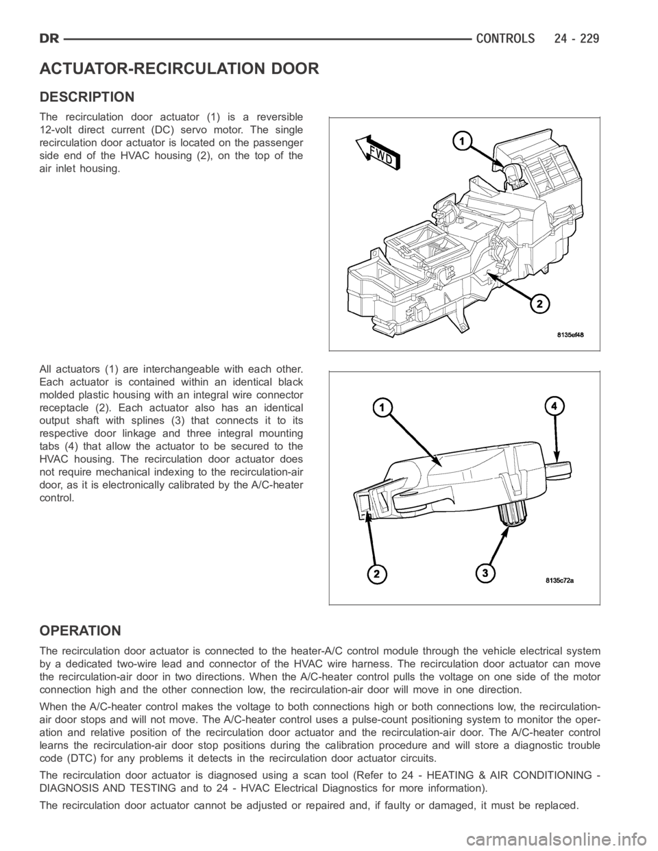
The recirculation door actuator (1) is a reversible
12-volt direct current (DC)servo motor. The single
recirculation door actuator is located on the passenger
side end of the HVAC housing (2), on the top of the
air inlet housing.
All actuators (1) are interchangeable with each other.
Each actuator is contained within an identical black
molded plastic housing with an integral wire connector
receptacle (2). Each actuator also has an identical
output shaft with splines (3) that connects it to its
respective door linkage and three integral mounting
tabs (4) that allow the actuator to be secured to the
HVAC housing. The recirculation door actuator does
not require mechanical indexing to the recirculation-air
door, as it is electronically calibrated by the A/C-heater
control.
OPERATION
The recirculation door actuator is connected to the heater-A/C control module through the vehicle electrical system
by a dedicated two-wire lead and connector of the HVAC wire harness. The recirculation door actuator can move
the recirculation-air door in two directions. When the A/C-heater control pulls the voltage on one side of the motor
connection high and the other connection low, the recirculation-air doorwill move in one direction.
When the A/C-heater control makes the voltage to both connections high or both connections low, the recirculation-
air door stops and will not move. The A/C-heater control uses a pulse-countpositioning system to monitor the oper-
ation and relative position of the recirculation door actuator and the recirculation-air door. The A/C-heater control
learns the recirculation-air door stop positions during the calibrationprocedure and will store a diagnostic trouble
code (DTC) for any problems it detects in the recirculation door actuator circuits.
The recirculation door actuator is diagnosed using a scan tool (Refer to 24- HEATING & AIR CONDITIONING -
DIAGNOSIS AND TESTING and to 24 - HVAC Electrical Diagnostics for more information).
The recirculation door actuator cannot be adjusted or repaired and, if faulty or damaged, it must be replaced.
Page 5073 of 5267
CLUTCH-A/C COMPRESSOR
DESCRIPTION
NOTE: Denso 10S17 A/C clutch assembly shown.
Visteon HS-18 compressor similar.
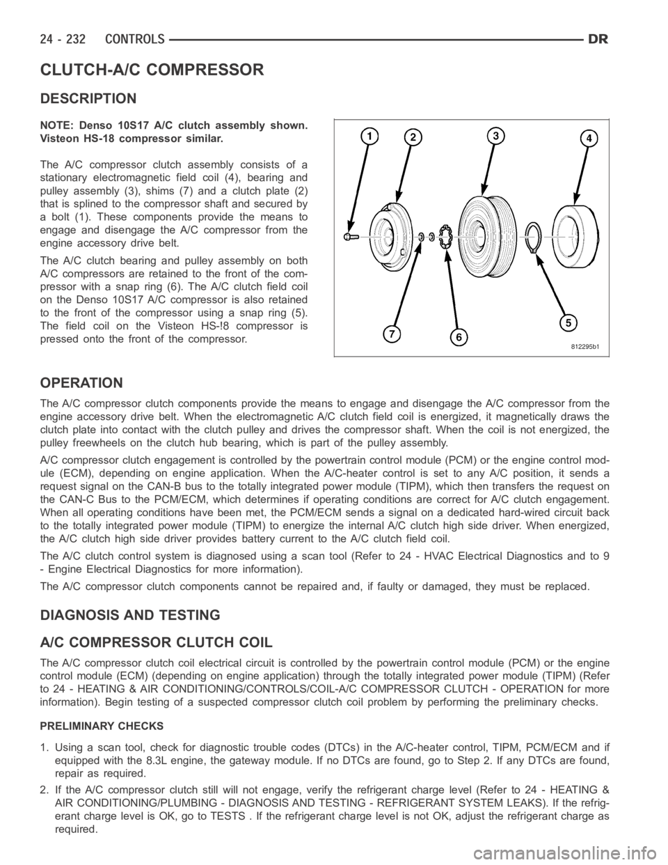
The A/C compressor clutch assembly consists of a
stationary electromagnetic field coil (4), bearing and
pulley assembly (3), shims (7) and a clutch plate (2)
that is splined to the compressor shaft and secured by
a bolt (1). These components provide the means to
engage and disengage the A/C compressor from the
engine accessory drive belt.
The A/C clutch bearing and pulley assembly on both
A/C compressors are retained to the front of the com-
pressor with a snap ring (6). The A/C clutch field coil
on the Denso 10S17 A/C compressor is also retained
to the front of the compressor using a snap ring (5).
The field coil on the Visteon HS-!8 compressor is
pressed onto the front of the compressor.
OPERATION
The A/C compressor clutch components provide the means to engage and disengage the A/C compressor from the
engine accessory drive belt. When the electromagnetic A/C clutch field coil is energized, it magnetically draws the
clutch plate into contact with the clutch pulley and drives the compressorshaft. When the coil is not energized, the
pulley freewheels on the clutch hub bearing, which is part of the pulley assembly.
A/C compressor clutch engagement is controlled by the powertrain controlmodule (PCM) or the engine control mod-
ule (ECM), depending on engine application. When the A/C-heater control is set to any A/C position, it sends a
request signal on the CAN-B bus to the totally integrated power module (TIPM), which then transfers the request on
the CAN-C Bus to the PCM/ECM, which determines if operating conditions arecorrect for A/C clutch engagement.
When all operating conditions have been met, the PCM/ECM sends a signal on adedicated hard-wired circuit back
to the totally integrated power module (TIPM) to energize the internal A/Cclutch high side driver. When energized,
the A/C clutch high side driver provides battery current to the A/C clutch field coil.
The A/C clutch control system is diagnosed using a scan tool (Refer to 24 - HVAC Electrical Diagnostics and to 9
- Engine Electrical Diagnostics for more information).
The A/C compressor clutch components cannot be repaired and, if faulty or damaged, they must be replaced.
DIAGNOSIS AND TESTING
A/CCOMPRESSORCLUTCHCOIL
The A/C compressor clutch coil electrical circuit is controlled by the powertrain control module (PCM) or the engine
control module (ECM) (depending on engine application) through the totally integrated power module (TIPM) (Refer
to 24 - HEATING & AIR CONDITIONING/CONTROLS/COIL-A/C COMPRESSOR CLUTCH -OPERATION for more
information). Begin testing of a suspected compressor clutch coil problem by performing the preliminary checks.
PRELIMINARY CHECKS
1. Using a scan tool, check for diagnostic trouble codes (DTCs) in the A/C-heater control, TIPM, PCM/ECM and if
equipped with the 8.3L engine, the gateway module. If no DTCs are found, go to Step 2. If any DTCs are found,
repair as required.
2. If the A/C compressor clutch still will not engage, verify the refrigerant charge level (Refer to 24 - HEATING &
AIR CONDITIONING/PLUMBING - DIAGNOSIS AND TESTING - REFRIGERANT SYSTEM LEAKS). If the refrig-
erant charge level is OK, go to TESTS . If the refrigerant charge level is notOK, adjust the refrigerant charge as
required.
Page 5074 of 5267
TESTS
1. Verify the battery state of charge (Refer to 8 - ELECTRICAL/BATTERY SYSTEM/BATTERY - DIAGNOSIS AND
TESTING).
2. Connect an ammeter (0 to 10 ampere scale selected) in series with the clutch coil feed terminal. Connect a
voltmeter (0 to 20 volt scale selected) to measure voltage across the battery and the clutch coil.
3. With the A/C-heater control in the A/C mode and the blower motor at low speed, start the engine and allow it to
run at a normal idle speed.
4. The A/C compressor clutch should engage immediately, and the clutch coil supply voltage should be within two
volts of the battery voltage. If the coil supply voltage is OK, go to Step 5. If the coil supply voltage is not within
two volts of battery voltage, test the clutch coil feed circuit for excessive voltage drop and repair as necessary.
5. For the acceptable A/C clutch coil current draw specifications refer to24 - HEATING & AIR CONDITIONING -
SPECIFICATIONS. Specifications apply for a work area temperature of 21° C(70° F). If voltage is more than
12.5 volts, add electrical loads by turning on electrical accessories until voltage reads below 12.5 volts.
STANDARD PROCEDURE
A/C CLUTCH PLATE INSPECTION
NOTE: The A/C clutch can be serviced inthe vehicle. The refrigerant systemcan remain fully-charged dur-
ing compressor clutch, pulley and bearing assembly, or coil replacement.
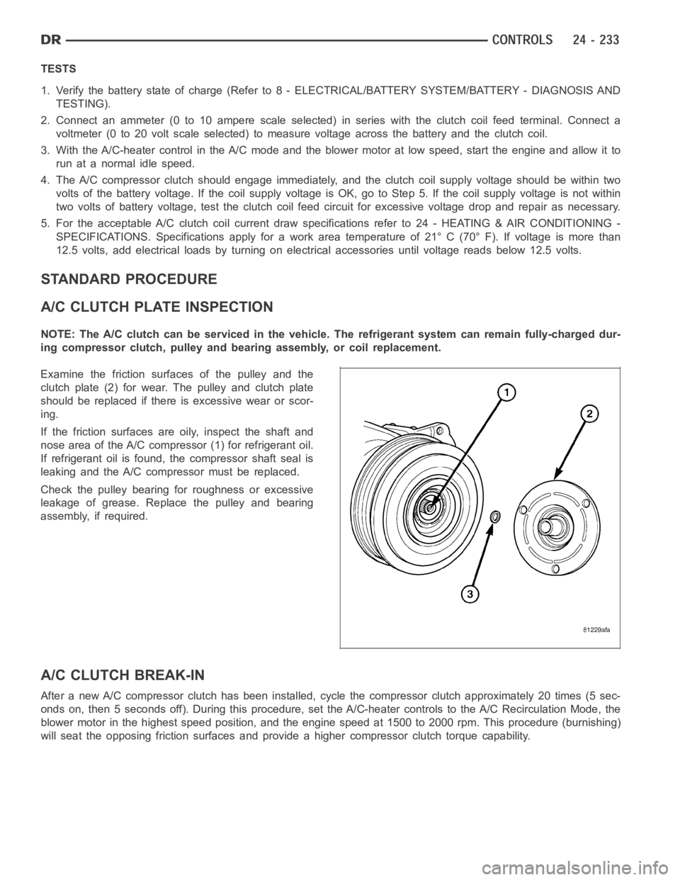
Examine the friction surfaces of the pulley and the
clutch plate (2) for wear. The pulley and clutch plate
should be replaced if there is excessive wear or scor-
ing.
If the friction surfaces are oily, inspect the shaft and
nose area of the A/C compressor (1) for refrigerant oil.
If refrigerant oil is found, the compressor shaft seal is
leaking and the A/C compressor must be replaced.
Check the pulley bearing for roughness or excessive
leakage of grease. Replace the pulley and bearing
assembly, if required.
A/C CLUTCH BREAK-IN
After a new A/C compressor clutch hasbeen installed, cycle the compressorclutch approximately 20 times (5 sec-
onds on, then 5 seconds off). During this procedure, set the A/C-heater controls to the A/C Recirculation Mode, the
blower motor in the highest speed position, and the engine speed at 1500 to 2000 rpm. This procedure (burnishing)
will seat the opposing friction surfaces and provide a higher compressor clutch torque capability.
Page 5077 of 5267
1. Disconnect and isolate negative battery cable.
2. Remove the accessory drive belt (Refer to 7 -
COOLING/ACCESSORY DRIVE/BELTS-DRIVE -
REMOVAL).
3. Raise and support the vehicle.
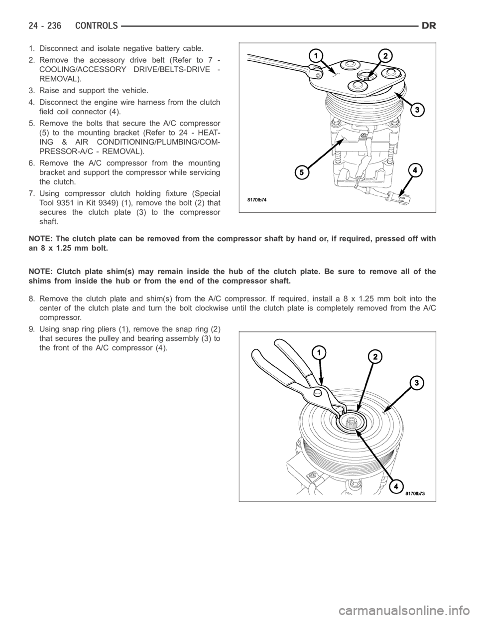
4. Disconnect the engine wire harness from the clutch
field coil connector (4).
5. Remove the bolts that secure the A/C compressor
(5)tothemountingbracket(Referto24-HEAT-
ING & AIR CONDITIONING/PLUMBING/COM-
PRESSOR-A/C - REMOVAL).
6. Remove the A/C compressor from the mounting
bracket and support the compressor while servicing
the clutch.
7. Using compressor clutch holding fixture (Special
Tool 9351 in Kit 9349) (1), remove the bolt (2) that
secures the clutch plate (3) to the compressor
shaft.
NOTE: The clutch plate can be removed from the compressor shaft by hand or, if required, pressed off with
an 8 x 1.25 mm bolt.
NOTE: Clutch plate shim(s) may remain inside the hub of the clutch plate. Besure to remove all of the
shims from inside the hub or from the end of the compressor shaft.
8. Remove the clutch plate and shim(s) from the A/C compressor. If required, install a 8 x 1.25 mm bolt into the
centeroftheclutchplateandturntheboltclockwiseuntiltheclutchplate is completely removed from the A/C
compressor.
9. Using snap ring pliers (1), remove the snap ring (2)
that secures the pulley and bearing assembly (3) to
the front of the A/C compressor (4).
Page 5083 of 5267
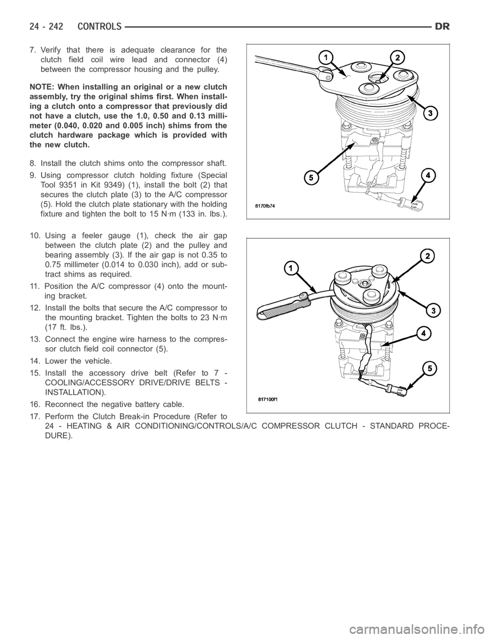
7. Verify that there is adequate clearance for the
clutch field coil wire lead and connector (4)
between the compressor housing and the pulley.
NOTE: When installing an original or a new clutch
assembly, try the original shims first. When install-
ing a clutch onto a compressor that previously did
not have a clutch, use the 1.0, 0.50 and 0.13 milli-
meter (0.040, 0.020 and 0.005 inch) shims from the
clutch hardware package which is provided with
the new clutch.
8. Install the clutch shims onto the compressor shaft.
9. Using compressor clutch holding fixture (Special
Tool 9351 in Kit 9349) (1), install the bolt (2) that
secures the clutch plate (3) to the A/C compressor
(5). Hold the clutch plate stationary with the holding
fixture and tighten the bolt to 15 Nꞏm (133 in. lbs.).
10. Using a feeler gauge (1), check the air gap
between the clutch plate (2) and the pulley and
bearing assembly (3). If the air gap is not 0.35 to
0.75 millimeter (0.014 to 0.030 inch), add or sub-
tract shims as required.
11. Position the A/C compressor (4) onto the mount-
ing bracket.
12. Install the bolts that secure the A/C compressor to
themountingbracket.Tightentheboltsto23Nꞏm
(17 ft. lbs.).
13. Connect the engine wire harness to the compres-
sor clutch field coil connector (5).
14. Lower the vehicle.
15. Install the accessory drive belt (Refer to 7 -
COOLING/ACCESSORY DRIVE/DRIVE BELTS -
INSTALLATION).
16. Reconnect the negative battery cable.
17. Perform the Clutch Break-in Procedure (Refer to
24 - HEATING & AIR CONDITIONING/CONTROLS/A/C COMPRESSOR CLUTCH - STANDARD PROCE-
DURE).
Page 5084 of 5267
CONTROL-A/C HEATER
DESCRIPTION
MANUAL SINGLE ZONE
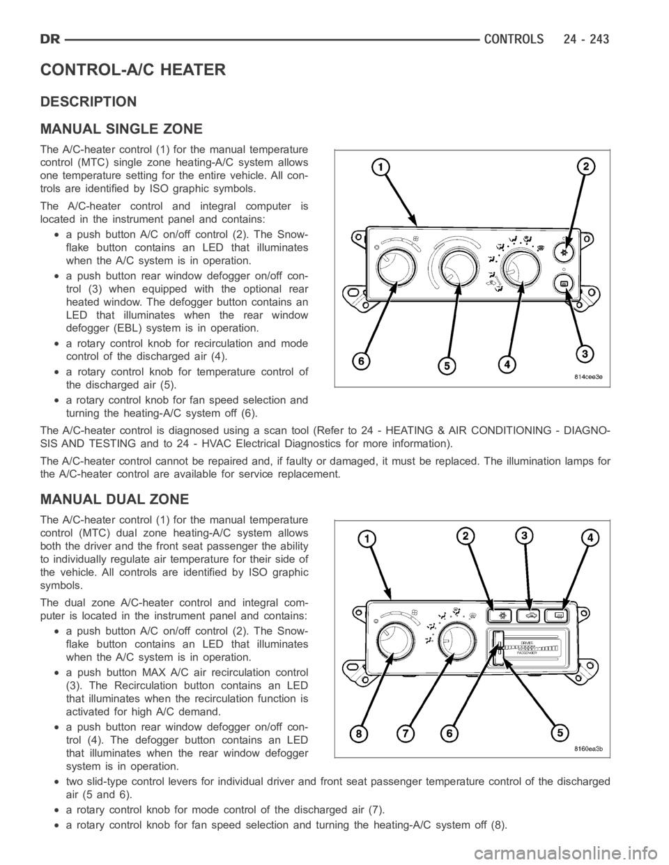
The A/C-heater control (1) for the manual temperature
control (MTC) single zoneheating-A/C system allows
one temperature setting for the entire vehicle. All con-
trols are identified by ISO graphic symbols.
The A/C-heater control and integral computer is
located in the instrument panel and contains:
a push button A/C on/off control (2). The Snow-
flake button contains an LED that illuminates
when the A/C system is in operation.
a push button rear window defogger on/off con-
trol (3) when equipped with the optional rear
heated window. The defogger button contains an
LED that illuminates when the rear window
defogger (EBL) system is in operation.
a rotary control knob for recirculation and mode
control of the discharged air (4).
a rotary control knob for temperature control of
thedischargedair(5).
a rotary control knob for fan speed selection and
turning the heating-A/C system off (6).
The A/C-heater control is diagnosed using a scan tool (Refer to 24 - HEATING& AIR CONDITIONING - DIAGNO-
SIS AND TESTING and to 24 - HVAC Electrical Diagnostics for more information).
The A/C-heater control cannot be repaired and, if faulty or damaged, it must be replaced. The illumination lamps for
the A/C-heater control are available for service replacement.
MANUAL DUAL ZONE
The A/C-heater control (1) for the manual temperature
control (MTC) dual zone heating-A/C system allows
both the driver and the front seat passenger the ability
to individually regulate air temperature for their side of
the vehicle. All controls are identified by ISO graphic
symbols.
The dual zone A/C-heater control and integral com-
puter is located in the instrument panel and contains:
a push button A/C on/off control (2). The Snow-
flake button contains an LED that illuminates
when the A/C system is in operation.
a push button MAX A/C air recirculation control
(3). The Recirculation button contains an LED
that illuminates when the recirculation function is
activated for high A/C demand.
a push button rear window defogger on/off con-
trol (4). The defogger button contains an LED
that illuminates when the rear window defogger
system is in operation.
two slid-type control levers for individual driver and front seat passenger temperature control of the discharged
air (5 and 6).
a rotary control knob for mode control of the discharged air (7).
a rotary control knob for fan speed selection and turning the heating-A/C system off (8).