2006 DODGE RAM SRT-10 air conditioning
[x] Cancel search: air conditioningPage 5102 of 5267
INSTALLATION
1. Position the demister ducts onto the instrument
panel cover.
2. Install the two screws that secure each demister
duct to the instrument panel cover. Tighten the
screws to 2.2 Nꞏm (20 in. lbs.).
3. Install the instrument panel cover (Refer to 23 -
BODY/INSTRUMENT PANEL/COVER-INSTRU-
MENT PANEL - INSTALLATION).
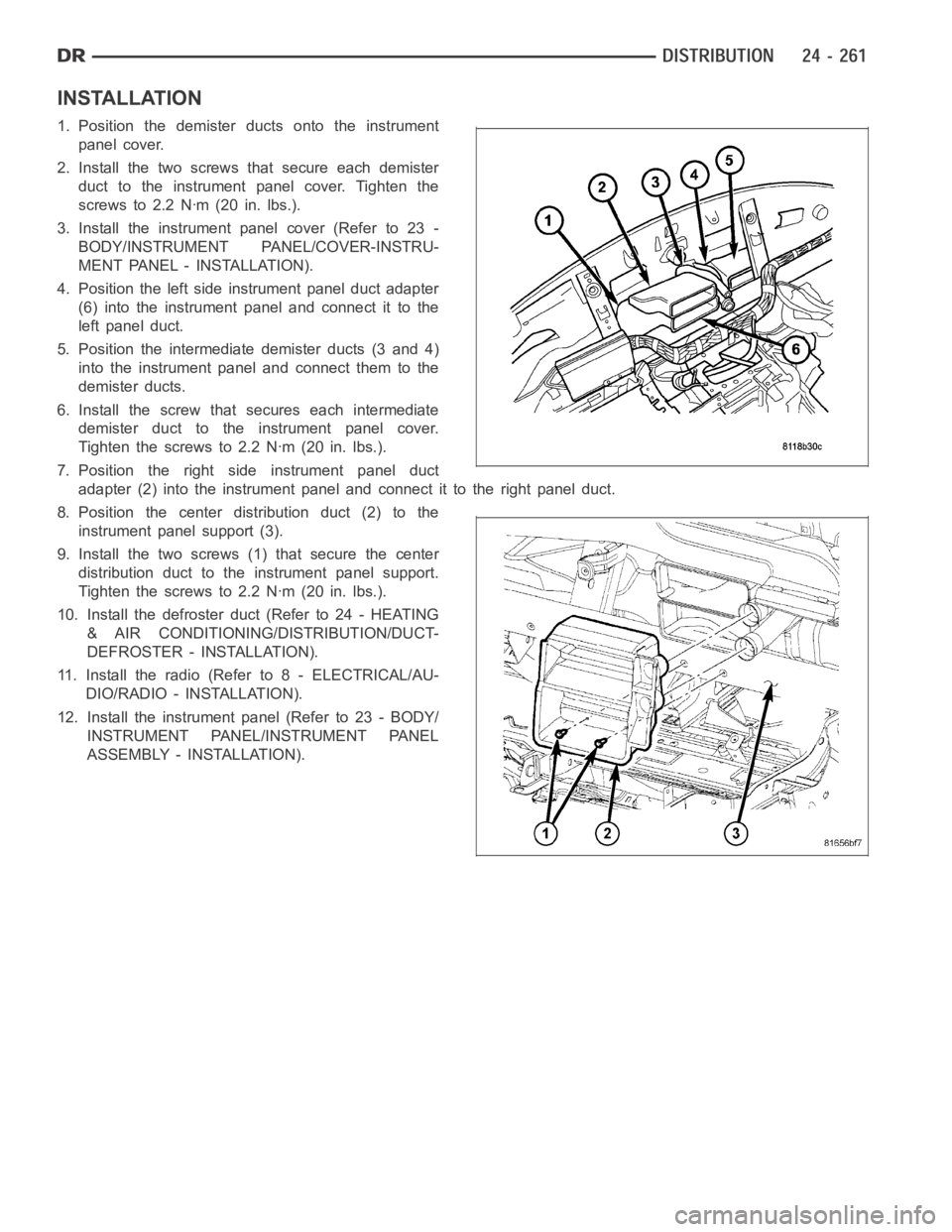
4. Position the left side instrument panel duct adapter
(6) into the instrument panel and connect it to the
left panel duct.
5. Position the intermediate demister ducts (3 and 4)
into the instrument panel and connect them to the
demister ducts.
6. Install the screw that secures each intermediate
demister duct to the instrument panel cover.
Tighten the screws to 2.2 Nꞏm (20 in. lbs.).
7. Position the right side instrument panel duct
adapter (2) into the instrument panel and connect it to the right panel duct.
8. Position the center distribution duct (2) to the
instrument panel support (3).
9. Install the two screws (1) that secure the center
distribution duct to the instrument panel support.
Tighten the screws to 2.2 Nꞏm (20 in. lbs.).
10. Install the defroster duct (Refer to 24 - HEATING
& AIR CONDITIONING/DISTRIBUTION/DUCT-
DEFROSTER - INSTALLATION).
11. Install the radio (Refer to 8 - ELECTRICAL/AU-
DIO/RADIO - INSTALLATION).
12. Install the instrument panel (Refer to 23 - BODY/
INSTRUMENT PANEL/INSTRUMENT PANEL
ASSEMBLY - INSTALLATION).
Page 5104 of 5267
REMOVAL
HVAC HOUSING ASSEMBLY
WARNING: Refer to the applicable warnings and cautions for this system before performing the following
operation (Refer to 24 - HEATING & AIR CONDITIONING/PLUMBING - WARNINGS) and (Refer to 24 - HEAT-
ING & AIR CONDITIONING/PLUMBING - CAUTIONS). Failure to follow the warnings and cautions could result
in possible personal injury or death.
WARNING: On vehicles equipped with airbags, disable the airbag system before attempting any steering
wheel, steering column, or instrument panel component diagnosis or service. Disconnect and isolate the
negative battery (ground) cable, then wait two minutes for the airbag system capacitor to discharge before
performing further diagnosis or service. This is the only sure way to disable the airbag system. Failure to
take the proper precautions could result in accidental airbag deploymentand possible personal injury or
death.
NOTE: The HVAC housing must be removedfrom the vehicle and disassembled for service of the A/C evap-
orator, evaporator temperature sensor, mode-air and blend-air doors.
1. Recover the refrigerant from the refrigerant system
(Refer to 24 - HEATING & AIR CONDITIONING/
PLUMBING - STANDARD PROCEDURE -
REFRIGERANT SYSTEM RECOVERY).
2. Drain the engine cooling system (Refer to 7 -
COOLING - STANDARD PROCEDURE - COOL-
ING SYSTEM DRAIN).
3. Disconnect and isolate the negative battery cable.
4. Disconnect the A/C liquid line and the A/C accumu-
lator from the A/C evaporator (Refer to 24 - HEAT-
ING & AIR CONDITIONING/PLUMBING/LINE-A/C
LIQUID - REMOVAL) and (Refer to 24 - HEATING
& AIR CONDITIONING/PLUMBING/ACCUMULA-
TOR-A/C - REMOVAL).
5. Disconnect the heater hoses from the heater core
tubes.
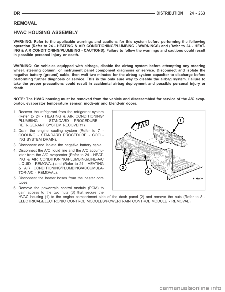
6. Remove the powertrain control module (PCM) to
gain access to the two nuts (3) that secure the
HVAC housing (1) to the engine compartment side of the dash panel (2) and remove the nuts (Refer to 8 -
ELECTRICAL/ELECTRONIC CONTROL MODULES/POWERTRAIN CONTROL MODULE - REMOVAL).
Page 5105 of 5267
7. On Mega Cab models, remove the floor console
duct (Refer to 24 - HEATING & AIR CONDITION-
ING/DISTRIBUTION/DUCT-FLOOR CONSOLE -
REMOVAL).
8. Remove the instrument panel from the passenger
compartment (Refer to 23 - BODY/INSTRUMENT
PANEL ASSEMBLY - REMOVAL).
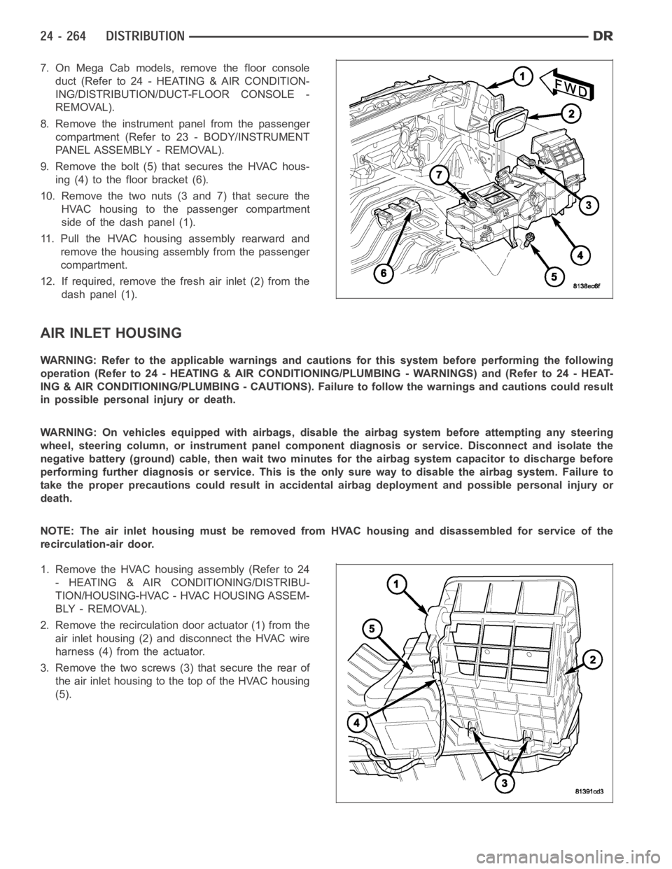
9. Remove the bolt (5) that secures the HVAC hous-
ing (4) to the floor bracket (6).
10. Remove the two nuts (3 and 7) that secure the
HVAC housing to the passenger compartment
side of the dash panel (1).
11. Pull the HVAC housing assembly rearward and
remove the housing assembly from the passenger
compartment.
12. If required, remove the fresh air inlet (2) from the
dash panel (1).
AIR INLET HOUSING
WARNING: Refer to the applicable warnings and cautions for this system before performing the following
operation (Refer to 24 - HEATING & AIR CONDITIONING/PLUMBING - WARNINGS) and (Refer to 24 - HEAT-
ING & AIR CONDITIONING/PLUMBING - CAUTIONS). Failure to follow the warnings and cautions could result
in possible personal injury or death.
WARNING: On vehicles equipped with airbags, disable the airbag system before attempting any steering
wheel, steering column, or instrument panel component diagnosis or service. Disconnect and isolate the
negative battery (ground) cable, then wait two minutes for the airbag system capacitor to discharge before
performing further diagnosis or service. This is the only sure way to disable the airbag system. Failure to
take the proper precautions could result in accidental airbag deploymentand possible personal injury or
death.
NOTE: The air inlet housing must be removed from HVAC housing and disassembled for service of the
recirculation-air door.
1. Remove the HVAC housing assembly (Refer to 24
- HEATING & AIR CONDITIONING/DISTRIBU-
TION/HOUSING-HVAC - HVAC HOUSING ASSEM-
BLY - REMOVAL).
2. Remove the recirculation door actuator (1) from the
air inlet housing (2) and disconnect the HVAC wire
harness (4) from the actuator.
3. Remove the two screws (3) that secure the rear of
the air inlet housing to the top of the HVAC housing
(5).
Page 5106 of 5267
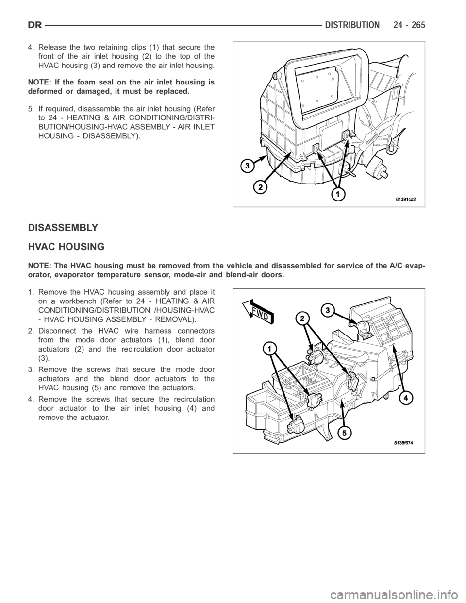
4. Release the two retaining clips (1) that secure the
front of the air inlet housing (2) to the top of the
HVAC housing (3) and remove the air inlet housing.
NOTE: If the foam seal on the air inlet housing is
deformed or damaged, it must be replaced.
5. If required, disassemblethe air inlet housing (Refer
to 24 - HEATING & AIR CONDITIONING/DISTRI-
BUTION/HOUSING-HVAC ASSEMBLY - AIR INLET
HOUSING - DISASSEMBLY).
DISASSEMBLY
HVAC HOUSING
NOTE: The HVAC housing must be removedfrom the vehicle and disassembled for service of the A/C evap-
orator, evaporator temperature sensor, mode-air and blend-air doors.
1. Remove the HVAC housing assembly and place it
on a workbench (Refer to 24 - HEATING & AIR
CONDITIONING/DISTRIBUTION /HOUSING-HVAC
- HVAC HOUSING ASSEMBLY - REMOVAL).
2. Disconnect the HVAC wire harness connectors
from the mode door actuators (1), blend door
actuators (2) and the recirculation door actuator
(3).
3. Remove the screws that secure the mode door
actuators and the blend door actuators to the
HVAC housing (5) and remove the actuators.
4. Remove the screws that secure the recirculation
door actuator to the air inlet housing (4) and
remove the actuator.
Page 5112 of 5267
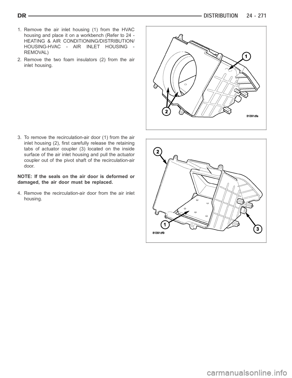
1. Remove the air inlet housing (1) from the HVAC
housing and place it on a workbench (Refer to 24 -
HEATING & AIR CONDITIONING/DISTRIBUTION/
HOUSING-HVAC - AIR INLET HOUSING -
REMOVAL)
2. Remove the two foam insulators (2) from the air
inlet housing.
3. To remove the recirculation-air door (1) from the air
inlet housing (2), first carefully release the retaining
tabs of actuator coupler (3) located on the inside
surface of the air inlet housing and pull the actuator
coupler out of the pivot shaft of the recirculation-air
door.
NOTE: If the seals on the air door is deformed or
damaged, the air door must be replaced.
4. Remove the recirculation-air door from the air inlet
housing.
Page 5117 of 5267
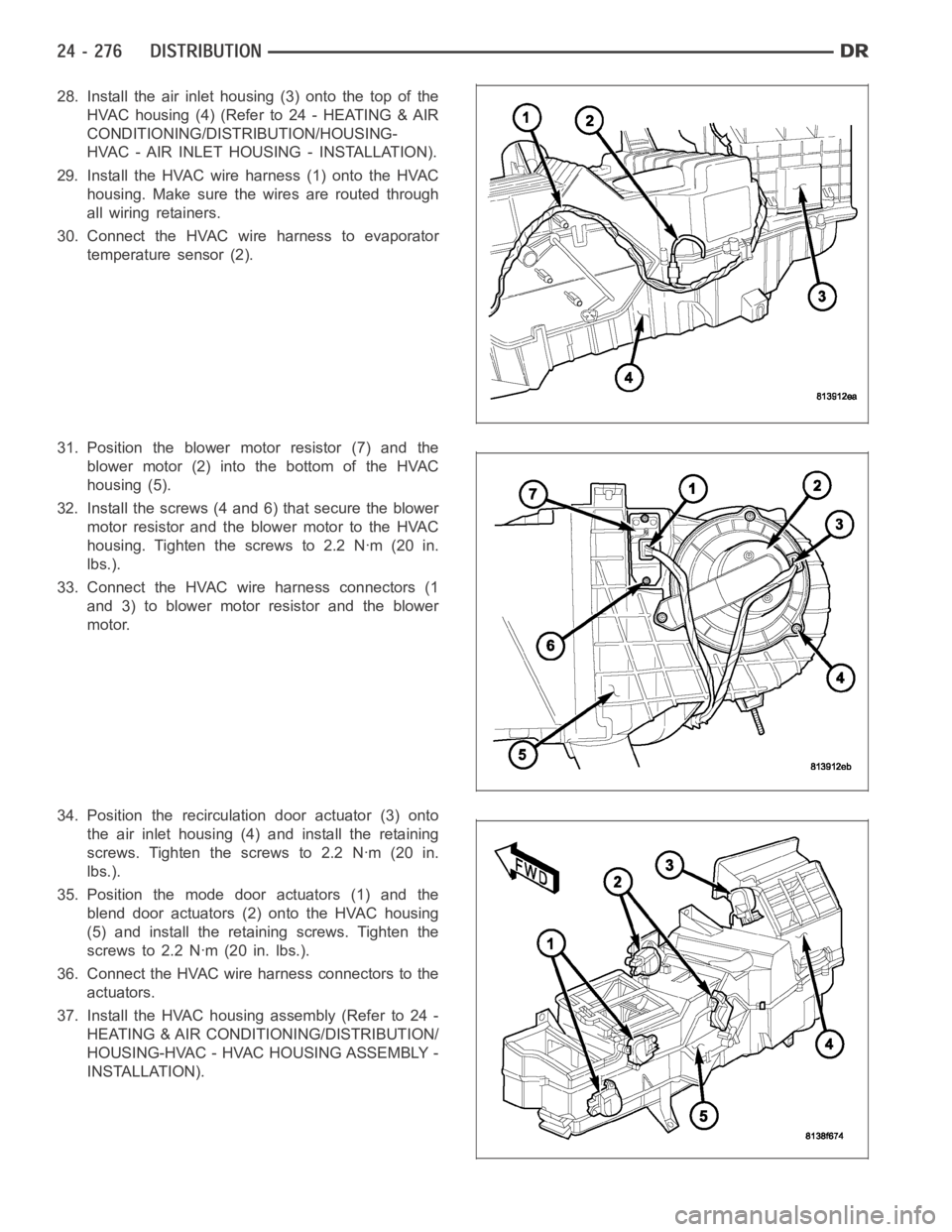
28. Install the air inlet housing (3) onto the top of the
HVAC housing (4) (Refer to 24 - HEATING & AIR
CONDITIONING/DISTRIBUTION/HOUSING-
HVAC - AIR INLET HOUSING - INSTALLATION).
29. Install the HVAC wire harness (1) onto the HVAC
housing. Make sure the wires are routed through
all wiring retainers.
30. Connect the HVAC wire harness to evaporator
temperature sensor (2).
31. Position the blower motor resistor (7) and the
blower motor (2) into the bottom of the HVAC
housing (5).
32. Install the screws (4 and 6) that secure the blower
motor resistor and the blower motor to the HVAC
housing. Tighten the screws to 2.2 Nꞏm (20 in.
lbs.).
33. Connect the HVAC wire harness connectors (1
and 3) to blower motor resistor and the blower
motor.
34. Position the recirculation door actuator (3) onto
the air inlet housing (4) and install the retaining
screws. Tighten the screws to 2.2 Nꞏm (20 in.
lbs.).
35. Position the mode door actuators (1) and the
blend door actuators (2) onto the HVAC housing
(5) and install the retaining screws. Tighten the
screws to 2.2 Nꞏm (20 in. lbs.).
36. Connect the HVAC wire harness connectors to the
actuators.
37. Install the HVAC housing assembly (Refer to 24 -
HEATING & AIR CONDITIONING/DISTRIBUTION/
HOUSING-HVAC - HVAC HOUSING ASSEMBLY -
INSTALLATION).
Page 5118 of 5267

AIR INLET HOUSING
NOTE: The air inlet housing must be removed from HVAC housing and disassembled for service of the
recirculation-air door.
NOTE: If the seals on the air door is deformed or
damaged, the air door must be replaced.
1. Position the recirculation-air door (1) into the air
inlet housing (2).
CAUTION: Make sure that the recirculation-air
door pivot shaft is properly seated in the pivot
seat located in the air inlet housing.
2. Align the actuator coupler (3) with the recirculation-
air door pivot shaft and install the coupler until the
coupler retaining tabs are fully engaged to the air
inlet housing. Be sure to install the coupler with the
coupler arm located between the two stop tabs on
the air inlet housing.
3. Install the two foam insulators (2) into the air inlet
housing (1).
4. Install the air inlet housing onto the HVAC housing
(Refer to 24 - HEATING & AIR CONDITIONING/
DISTRIBUTION/HOUSING-HVAC - AIR INLET
HOUSING - INSTALLATION).
INSTALLATION
HVAC HOUSING ASSEMBLY
NOTE: The HVAC housing must be removedfrom the vehicle and disassembled for service of the A/C evap-
orator, evaporator temperature sensor, mode-air and blend-air doors.
Page 5119 of 5267
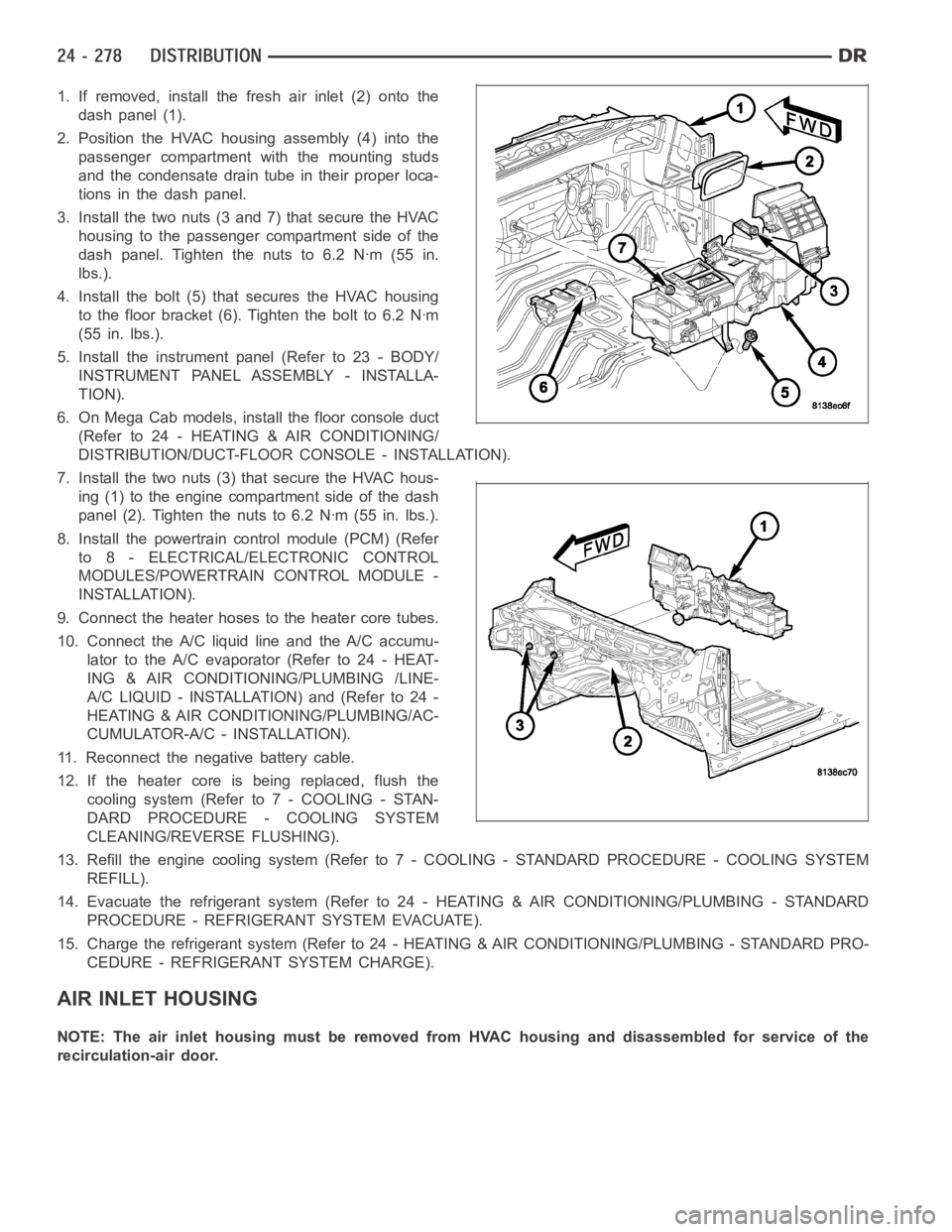
1. If removed, install the fresh air inlet (2) onto the
dash panel (1).
2. Position the HVAC housing assembly (4) into the
passenger compartment with the mounting studs
and the condensate drain tube in their proper loca-
tions in the dash panel.
3. Install the two nuts (3 and 7) that secure the HVAC
housing to the passenger compartment side of the
dash panel. Tighten the nuts to 6.2 Nꞏm (55 in.
lbs.).
4. Install the bolt (5) that secures the HVAC housing
to the floor bracket (6). Tighten the bolt to 6.2 Nꞏm
(55 in. lbs.).
5. Install the instrument panel (Refer to 23 - BODY/
INSTRUMENT PANEL ASSEMBLY - INSTALLA-
TION).
6. On Mega Cab models, install the floor console duct
(Refer to 24 - HEATING & AIR CONDITIONING/
DISTRIBUTION/DUCT-FLOOR CONSOLE - INSTALLATION).
7. Install the two nuts (3) that secure the HVAC hous-
ing (1) to the engine compartment side of the dash
panel (2). Tighten the nuts to 6.2 Nꞏm (55 in. lbs.).
8. Install the powertrain control module (PCM) (Refer
to 8 - ELECTRICAL/ELECTRONIC CONTROL
MODULES/POWERTRAIN CONTROL MODULE -
INSTALLATION).
9. Connect the heater hoses to the heater core tubes.
10. Connect the A/C liquid line and the A/C accumu-
lator to the A/C evaporator (Refer to 24 - HEAT-
ING & AIR CONDITIONING/PLUMBING /LINE-
A/C LIQUID - INSTALLATION) and (Refer to 24 -
HEATING & AIR CONDITIONING/PLUMBING/AC-
CUMULATOR-A/C - INSTALLATION).
11. Reconnect the negative battery cable.
12. If the heater core is being replaced, flush the
coolingsystem(Referto7-COOLING-STAN-
DARD PROCEDURE - COOLING SYSTEM
CLEANING/REVERSE FLUSHING).
13. Refill the engine cooling system (Refer to 7 - COOLING - STANDARD PROCEDURE - COOLING SYSTEM
REFILL).
14. Evacuate the refrigerant system (Refer to 24 - HEATING & AIR CONDITIONING/PLUMBING - STANDARD
PROCEDURE - REFRIGERANT SYSTEM EVACUATE).
15. Charge the refrigerant system (Refer to 24 - HEATING & AIR CONDITIONING/PLUMBING - STANDARD PRO-
CEDURE - REFRIGERANT SYSTEM CHARGE).
AIR INLET HOUSING
NOTE: The air inlet housing must be removed from HVAC housing and disassembled for service of the
recirculation-air door.