2006 DODGE RAM SRT-10 air conditioning
[x] Cancel search: air conditioningPage 5120 of 5267
NOTE: If the foam seal on the air inlet housing is
deformed or damaged, it must be replaced.
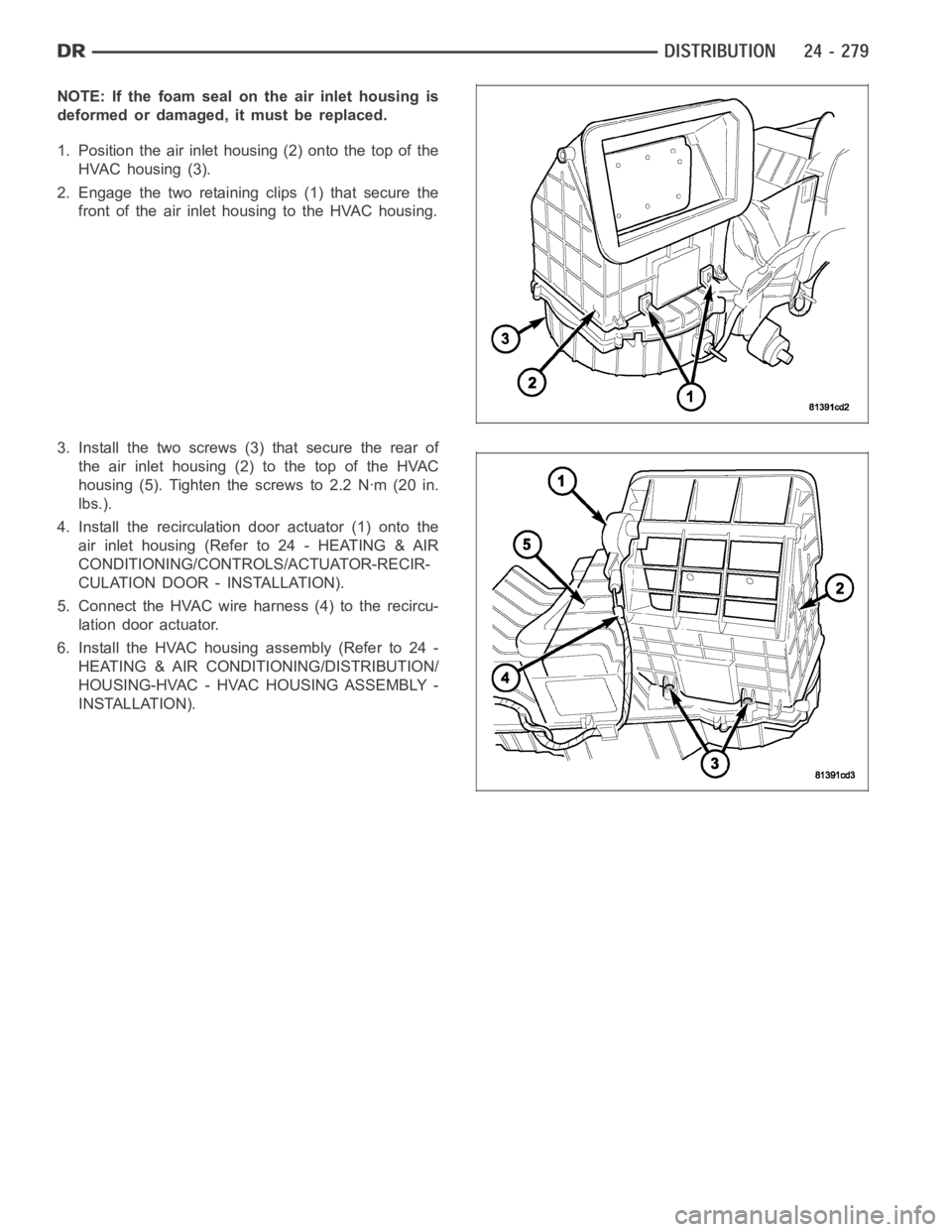
1. Position the air inlet housing (2) onto the top of the
HVAC housing (3).
2. Engage the two retaining clips (1) that secure the
front of the air inlet housing to the HVAC housing.
3. Install the two screws (3) that secure the rear of
the air inlet housing (2) to the top of the HVAC
housing (5). Tighten the screws to 2.2 Nꞏm (20 in.
lbs.).
4. Install the recirculation door actuator (1) onto the
air inlet housing (Refer to 24 - HEATING & AIR
CONDITIONING/CONTROLS/ACTUATOR-RECIR-
CULATION DOOR - INSTALLATION).
5. Connect the HVAC wire harness (4) to the recircu-
lation door actuator.
6. Install the HVAC housing assembly (Refer to 24 -
HEATING & AIR CONDITIONING/DISTRIBUTION/
HOUSING-HVAC - HVAC HOUSING ASSEMBLY -
INSTALLATION).
Page 5122 of 5267
NOTE: The blower motor is supplied with a 12V feed from the TIPM, through theresistor block, whenever
the ignition switch is in the RUN position. Due to an open circuit conditionwithin the blower motor control
switch the TIPM is UNABLE to detect an OPEN circuit for the blower motor.
To determine if an open condition exists within the blower motor circuit wiring, it is necessary to disconnect the
negative battery cable and check for continuity within the blower motor circuits using an ohmmeter. For circuit
descriptions and diagrams, refer to Air Conditioning/Heater in Group 8W -Wiring Diagrams.
OPERATION
Possible causes of the blower motor not operating include:
Faulty blower motor
Faulty blower motor circuit wiring or wire harness connectors
Faulty blower motor control
Possible causes of the blower motor not operating in one or more speeds include:
Faulty blower motor resistor
Faulty blower motor circuit wiring or wire harness connectors
Faulty blower motor control
VIBRATION
Possible causes of blower motor vibration include:
Improper blower motor mounting
Improper blower wheel mounting
Deformed blower wheel
Out of balance blower wheel due to foreign material in the wheel
Faulty blower motor
NOISE
To determine if the blower motor is the source of the noise, simply switch the blower motor from Off to On. To verify
that the blower motor is the source of the noise, unplug the blower motor wire harness connector and operate the
heating-A/C system. If the noise goes away, possible causes include:
Foreign material in the HVAC air inlet housing
Improper blower motor mounting
Improper blower wheel mounting
Faulty blower motor
Page 5129 of 5267
DIAGNOSIS AND TESTING
REFRIGERANT SYSTEM LEAKS
WARNING: R-134a service equipment or vehicle A/C system should not be pressure tested or leak tested
with compressed air. Mixture of air and R-134a can be combustible at elevated pressures. These mixtures
are potentially dangerous and may result in fire or explosion causing property damage, personal injury or
death.
Avoid breathing A/C refrigerant and lubricant vapor or mist. Exposure mayirritate eyes, nose and throat.
Use only approved service equipment meeting SAE requirements to discharge R-134a system. If accidental
system discharge occurs, ventilate work area before resuming service.
NOTE: If the A/C refrigerant system charge is empty or low, a leak in the A/C system is likely. Visually
inspect all A/C lines, fittings and components for an oily residue. Oil residue can be an indicator of an A/C
system leak location.
NOTE: The only way to correctly determine if the refrigerant system is fully charged with R-134a is to com-
pletely evacuate and recharge the A/C system.
Connect a suitable manifold gauge setand determine if the static A/C system pressure is above or below 345 kPa
(50 psi) (refer to 24 - HEATING & AIR CONDITIONING/PLUMBING - STANDARD PROCEDURE - REFRIGERANT
SYSTEM SERVICE EQUIPMENT). If less than 345 kPa (50 psi), proceed to SYSTEMEMPTY . If greater than 345
kPa (50 psi), go to SYSTEM LOW .
SYSTEM EMPTY
1. Evacuate the refrigerant system to the lowest degree of vacuum possible(approximately -88 kPa (- 26 in. Hg) or
greater vacuum) (Refer to 24 - HEATING & AIR CONDITIONING/PLUMBING - STANDARD PROCEDURE -
REFRIGERANT SYSTEM EVACUATE). Determine if the system holds a vacuum for 15 minutes. If vacuum is
held, a leak is probably not present. If system will not maintain vacuum level, proceed to Step 2.
2. Prepare and dispense 0.284 kilograms (10 ounces) of R-134a refrigerantinto the evacuated refrigerant system
(Refer to 24 - HEATING & AIR CONDITIONING/PLUMBING - STANDARD PROCEDURE - REFRIGERANT SYS-
TEM CHARGE) and proceed to Step 1 of the System Low procedure.
SYSTEM LOW
1. Position the vehicle in a wind-freework area. This will aid in detectingsmall leaks.
2. Operate the heating-A/C system with the engine at idle under the following conditions for at least five minutes.
Doors or windows open
Transmission in Park or Neutral with the parking brake set (depending on application)
A/C-heater controls set to outside air, full cool, panel mode, high blowerand with A/C compressor engaged
CAUTION: A leak detector only designed for R-12 refrigerant will not detect leaks in an R-134a refrigerant
system.
3. Shut the vehicle Off and wait 2-7 minutes. Then use an electronic leak detector that is designed to detect R-134a
refrigerant and search for leaks. Fittings, lines or components that appear to be oily usually indicate a refrigerant
leak. To inspect the A/C evaporator for leaks, insert the leak detector probe into the drain tube opening or an air
outlet. A dye for R-134a is available to aid in leak detection. Use only DaimlerChrysler approved refrigerant dye.
Page 5130 of 5267
STANDARD PROCEDURE
REFRIGERANT SYSTEM SERVICE EQUIPMENT
WARNING: Eye protection must be worn when servicing an A/C refrigerant system. Turn all valves off
(rotate clockwise) on the equipment being used before connecting or disconnecting service equipment from
the refrigerant system. Failure to observe these warnings may result in personal injury or death.
WARNING: Refer to the applicable warnings and cautions for this system before performing the following
operation (Refer to 24 - HEATING & AIR CONDITIONING/PLUMBING - WARNINGS) and (Refer to 24 - HEAT-
ING & AIR CONDITIONING/PLUMBING - CAUTIONS). Failure to follow the warnings and cautions could result
in possible personal injury or death.
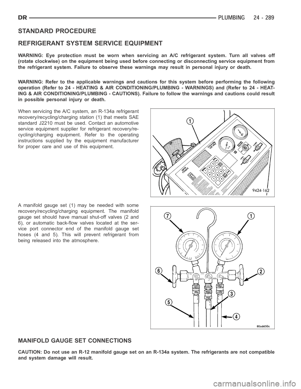
When servicing the A/C system, an R-134a refrigerant
recovery/recycling/charging station (1) that meets SAE
standard J2210 must be used. Contact an automotive
service equipment supplier for refrigerant recovery/re-
cycling/charging equipment. Refer to the operating
instructions supplied by the equipment manufacturer
for proper care and use of this equipment.
A manifold gauge set (1) may be needed with some
recovery/recycling/charging equipment. The manifold
gauge set should have manual shut-off valves (2 and
6), or automatic back-flow valves located at the ser-
vice port connector end of the manifold gauge set
hoses (4 and 5). This will prevent refrigerant from
being released into the atmosphere.
MANIFOLD GAUGE SET CONNECTIONS
CAUTION: Do not use an R-12 manifold gauge set on an R-134a system. The refrigerants are not compatible
and system damage will result.
Page 5131 of 5267
RECOVERY/RECYCLING/EVACUATION/CHARGING HOSE– The center manifold hose (Yellow, or White, with
Black stripe) (3) is used to recover, evacuate, and charge the refrigerantsystem. When the low or high pressure
valves on the manifold gauge set are opened, the refrigerant in the system will escape through this hose.
HIGH PRESSURE GAUGE HOSE– The high pressure hose (Red with Black stripe) (4) attaches to the high side
service port. This service port is located on the A/C discharge line. On this model, an A/C pressure transducer is
installed on the high side service port. A/C high-side pressures can be read using a scan tool. Refer to 9 - Engine
Electrical Diagnostics for more information.
LOW PRESSURE GAUGE HOSE– The low pressure hose (Blue with Black stripe) (5) attaches to the low side
service port. This service port is located either on the top of the A/C accumulator or on the A/C suction line near the
accumulator, depending on engine application.
REFRIGERANT SYSTEM RECOVERY
WARNING: Refer to the applicable warnings and cautions for this system before performing the following
operation (Refer to 24 - HEATING & AIR CONDITIONING/PLUMBING - WARNINGS) and (Refer to 24 - HEAT-
ING & AIR CONDITIONING/PLUMBING - CAUTIONS). Failure to follow the warnings and cautions could result
in possible personal injury or death.
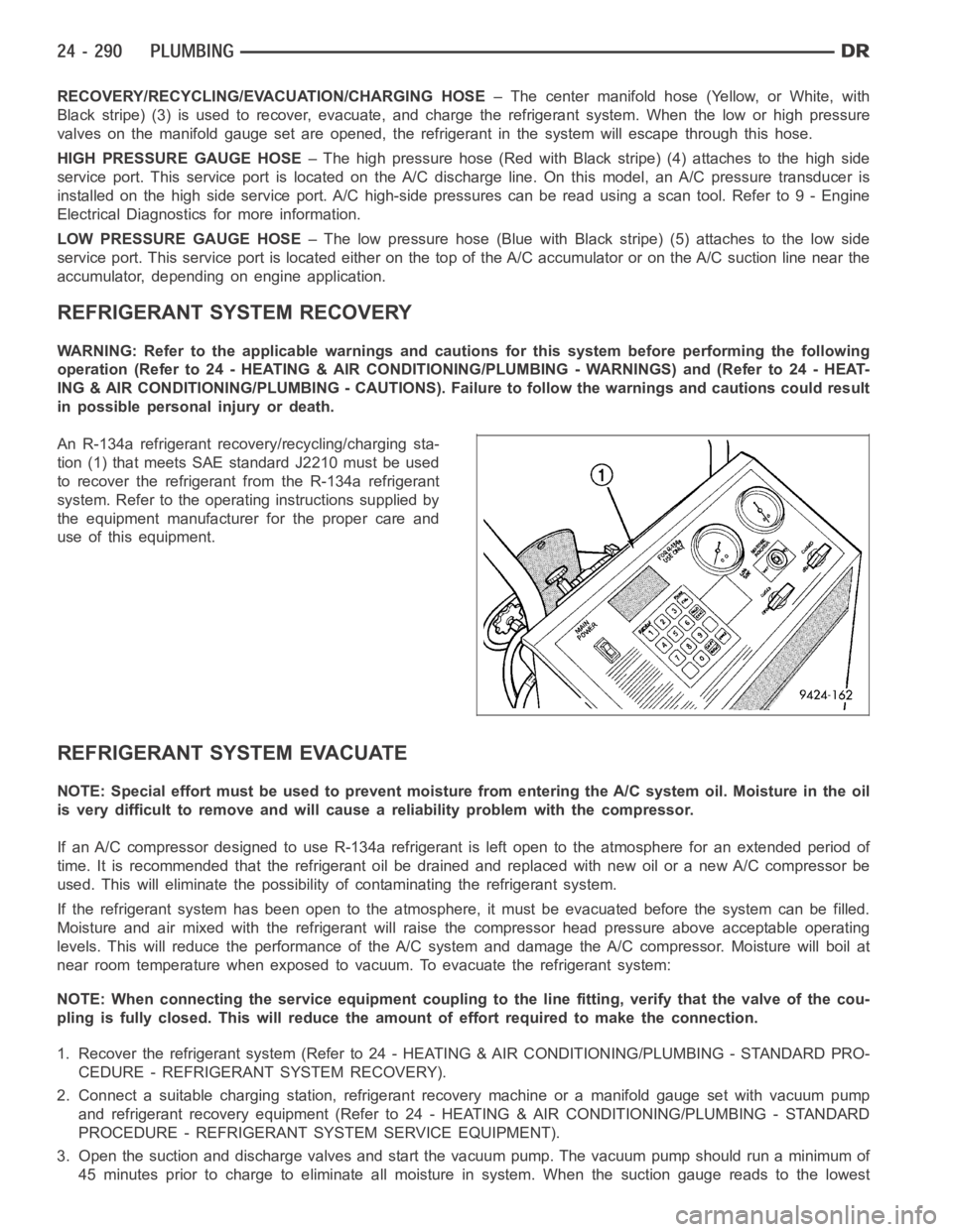
An R-134a refrigerant recovery/recycling/charging sta-
tion (1) that meets SAE standard J2210 must be used
to recover the refrigerant from the R-134a refrigerant
system. Refer to the operating instructions supplied by
the equipment manufacturer for the proper care and
use of this equipment.
REFRIGERANT SYSTEM EVACUATE
NOTE: Special effort must be used to prevent moisture from entering the A/Csystem oil. Moisture in the oil
is very difficult to remove and will cause a reliability problem with the compressor.
If an A/C compressor designed to use R-134a refrigerant is left open to the atmosphere for an extended period of
time. It is recommended that the refrigerant oil be drained and replaced with new oil or a new A/C compressor be
used. This will eliminate the possibility of contaminating the refrigerant system.
If the refrigerant system has been open to the atmosphere, it must be evacuated before the system can be filled.
Moisture and air mixed with the refrigerant will raise the compressor headpressure above acceptable operating
levels. This will reduce the performance of the A/C system and damage the A/C compressor. Moisture will boil at
near room temperature when exposed to vacuum. To evacuate the refrigerantsystem:
NOTE: When connecting the service equipment coupling to the line fitting,verify that the valve of the cou-
pling is fully closed. This will reduce the amount of effort required to make the connection.
1. Recover the refrigerant system (Refer to 24 - HEATING & AIR CONDITIONING/PLUMBING - STANDARD PRO-
CEDURE - REFRIGERANT SYSTEM RECOVERY).
2. Connect a suitable charging station, refrigerant recovery machine or amanifold gauge set with vacuum pump
and refrigerant recovery equipment (Refer to 24 - HEATING & AIR CONDITIONING/PLUMBING - STANDARD
PROCEDURE - REFRIGERANT SYSTEM SERVICE EQUIPMENT).
3. Open the suction and discharge valves and start the vacuum pump. The vacuum pump should run a minimum of
45minutespriortochargetoeliminateall moisture in system. When the suction gauge reads to the lowest
Page 5132 of 5267
degree of vacuum possible (approximately -88 kPa (- 26 in. Hg) or greater) for 30 minutes, close all valves and
turn off vacuum pump. If the system failsto reach specified vacuum, the refrigerant system likely has a leak that
must be corrected. If the refrigerantsystem maintains specified vacuum for at least 30 minutes, start the vacuum
pump, open the suction and discharge valves. Then allow the system to evacuate an additional 10 minutes.
4. Close all valves. Turn off and disconnect the vacuum pump.
5. Charge the refrigerant system (Refer to 24 - HEATING & AIR CONDITIONING/PLUMBING - STANDARD PRO-
CEDURE - REFRIGERANT SYSTEM CHARGE).
REFRIGERANT SYSTEM CHARGE
WARNING: Refer to the applicable warnings and cautions for this system before performing the following
operation (Refer to 24 - HEATING & AIR CONDITIONING/PLUMBING - WARNINGS) and (Refer to 24 - HEAT-
ING & AIR CONDITIONING/PLUMBING - CAUTIONS). Failure to follow the warnings and cautions could result
in possible personal injury or death.
NOTE: Always refer to the Underhood HVAC Specification Label for the refrigerant fill specification of the
vehicle being serviced.
After all refrigerant system leaks have been repaired and the refrigerantsystem has been evacuated, a refrigerant
charge can be injected into the system. For the proper amount of the refrigerant charge, refer to the Underhood
HVAC Specification Label.
An R-134a refrigerant recovery/recycling/charging station that meets SAE Standard J2210 must be used to charge
the refrigerant system with R-134a refrigerant. Refer to the operating instructions supplied by the equipment man-
ufacturer for proper care and use of this equipment.
CHARGING PROCEDURE
CAUTION: A small amount of refrigerant oil is removed from the A/C system each time the refrigerant sys-
tem is recovered and evacuated. Before charging the A/C system, you MUST replenish any oil lost during
the recovery process. Refer the equipment manufacturer instructions formore information.
1. Evacuate the refrigerant system (Refer to 24 - HEATING & AIR CONDITIONING/PLUMBING - STANDARD PRO-
CEDURE - REFRIGERANT SYSTEM EVACUATE).
2. A manifold gauge set and an R-134a refrigerant recovery/recycling/charging station that meets SAE standard
J2210 should be connected to the refrigerant system.
3. Measure the proper amount of refrigerant and heat it to 52° C (125° F) withthe charging station. See the oper-
ating instructions supplied by the equipment manufacturer for proper useof this equipment.
4. Open both the suction and discharge valves, then open the charge valve toallow the heated refrigerant to flow
into the system.
5. When the transfer of refrigerant has stopped, close both the suction anddischarge valves.
6. If all of the refrigerant charge did not transfer from the dispensing device, open all of the windows in the vehicle
and set the heating-A/C system controls so that the A/C compressor is engaged and the blower motor is oper-
ating at its lowest speed setting. Run the engine at a steady high idle (about 1400 rpm). If the A/C compressor
does not engage, test the compressor clutch control circuit and repair as required.
7. Open the low-side valve to allow the remaining refrigerant to transfer to the refrigerant system.
WARNING: Take care not to open the discharge (high pressure) valve at this time. Failure to follow this
warning could result in possible personal injury or death.
8. Disconnect the charging station and manifold gauge set from the refrigerant system service ports.
9. Reinstall the caps onto the refrigerant system service ports.
Page 5133 of 5267
ACCUMULATOR-A/C
DESCRIPTION
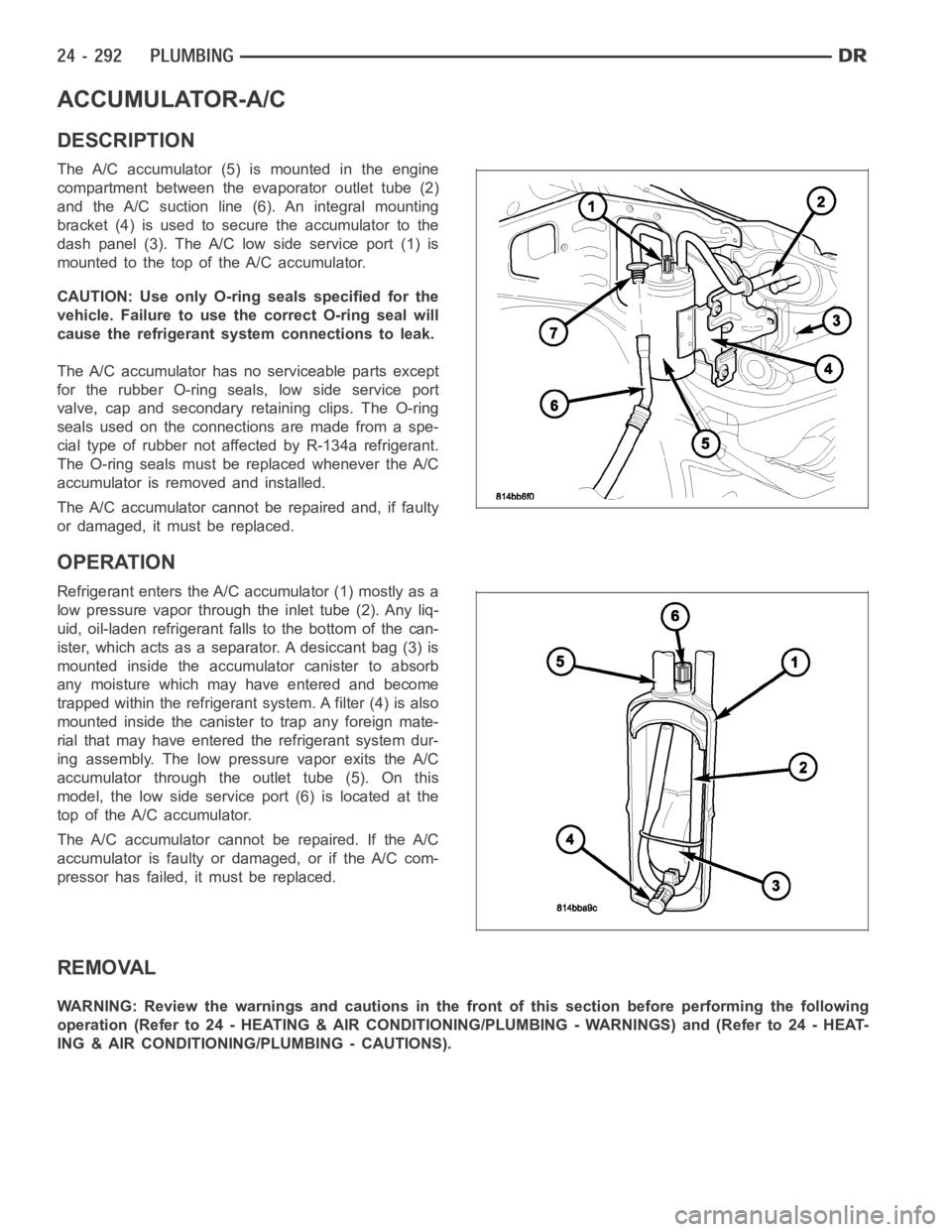
The A/C accumulator (5) is mounted in the engine
compartment between the evaporator outlet tube (2)
and the A/C suction line (6). An integral mounting
bracket (4) is used to secure the accumulator to the
dash panel (3). The A/C low side service port (1) is
mountedtothetopoftheA/Caccumulator.
CAUTION: Use only O-ring seals specified for the
vehicle. Failure to use the correct O-ring seal will
cause the refrigerant system connections to leak.
The A/C accumulator has no serviceable parts except
for the rubber O-ring seals, low side service port
valve, cap and secondary retaining clips. The O-ring
seals used on the connections are made from a spe-
cial type of rubber not affected by R-134a refrigerant.
The O-ring seals must be replaced whenever the A/C
accumulator is removed and installed.
The A/C accumulator cannot be repaired and, if faulty
or damaged, it must be replaced.
OPERATION
Refrigerant enters the A/C accumulator (1) mostly as a
low pressure vapor through the inlet tube (2). Any liq-
uid, oil-laden refrigerant falls to the bottom of the can-
ister, which acts as a separator. A desiccant bag (3) is
mounted inside the accumulator canister to absorb
any moisture which may have entered and become
trapped within the refrigerant system. A filter (4) is also
mounted inside the canister to trap any foreign mate-
rial that may have entered the refrigerant system dur-
ing assembly. The low pressure vapor exits the A/C
accumulator through the outlet tube (5). On this
model, the low side service port (6) is located at the
top of the A/C accumulator.
The A/C accumulator cannot be repaired. If the A/C
accumulator is faulty or damaged, or if the A/C com-
pressor has failed, it must be replaced.
REMOVAL
WARNING: Review the warnings and cautions in the front of this section before performing the following
operation (Refer to 24 - HEATING & AIR CONDITIONING/PLUMBING - WARNINGS) and (Refer to 24 - HEAT-
ING & AIR CONDITIONING/PLUMBING - CAUTIONS).
Page 5134 of 5267
1. Disconnect and isolate the negative battery cable.
2. Recover the refrigerant from the refrigerant system
(Refer to 24 - HEATING & AIR CONDITIONING/
PLUMBING - STANDARD PROCEDURE -
REFRIGERANT RECOVERY).
3. Remove the air filter housing cover to gain access
to the A/C accumulator (9) (Refer to 9 - ENGINE/
AIR INTAKE SYSTEM).
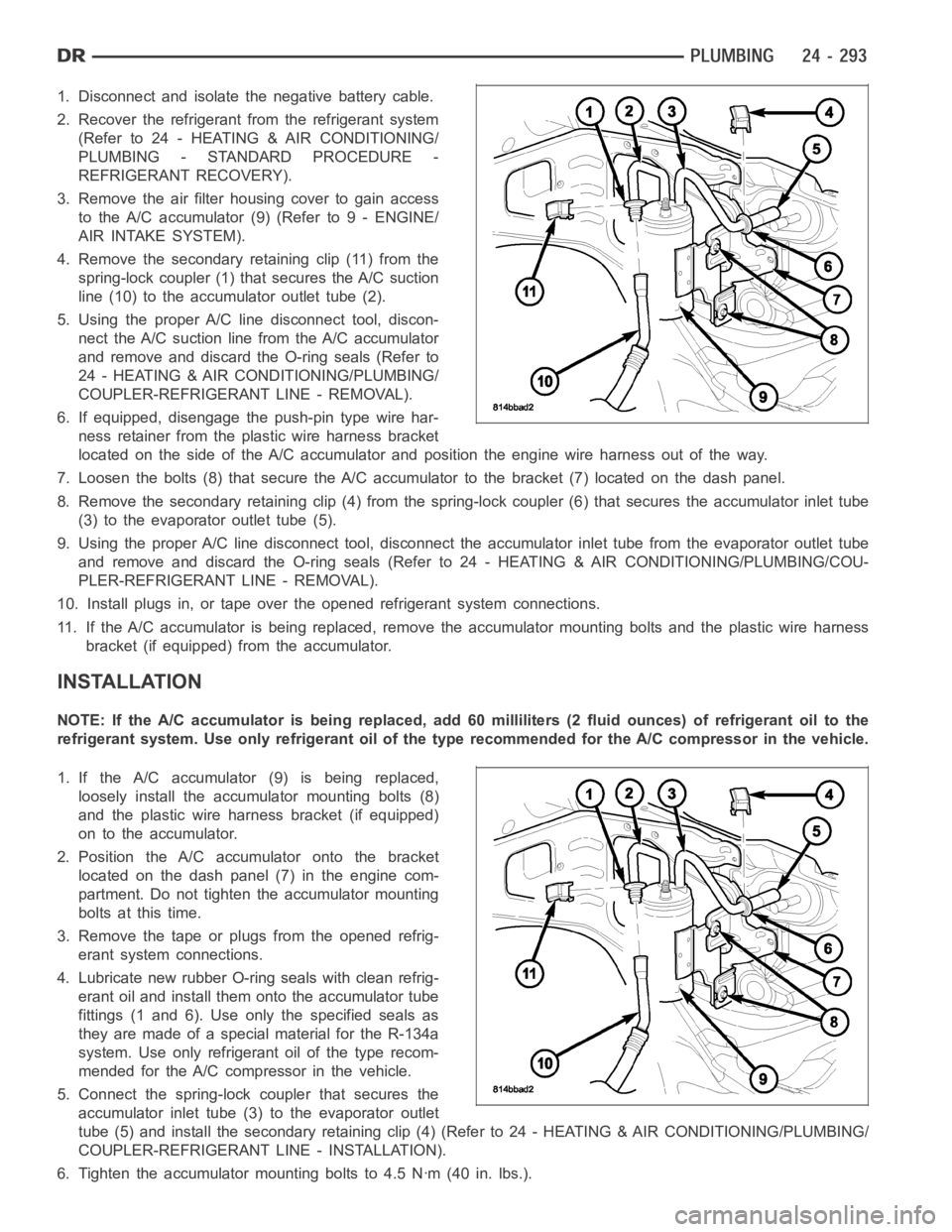
4. Remove the secondary retaining clip (11) from the
spring-lock coupler (1) that secures the A/C suction
line (10) to the accumulator outlet tube (2).
5. Using the proper A/C line disconnect tool, discon-
nect the A/C suction line from the A/C accumulator
and remove and discard the O-ring seals (Refer to
24 - HEATING & AIR CONDITIONING/PLUMBING/
COUPLER-REFRIGERANT LINE - REMOVAL).
6. If equipped, disengage the push-pin type wire har-
ness retainer from the plastic wire harness bracket
located on the side of the A/C accumulator and position the engine wire harness out of the way.
7. Loosen the bolts (8) that secure the A/C accumulator to the bracket (7) located on the dash panel.
8. Remove the secondary retaining clip (4) from the spring-lock coupler (6) that secures the accumulator inlet tube
(3) to the evaporator outlet tube (5).
9. Using the proper A/C line disconnect tool, disconnect the accumulator inlet tube from the evaporator outlet tube
and remove and discard the O-ring seals (Refer to 24 - HEATING & AIR CONDITIONING/PLUMBING/COU-
PLER-REFRIGERANT LINE - REMOVAL).
10. Install plugs in, or tape over the opened refrigerant system connections.
11. If the A/C accumulator is being replaced, remove the accumulator mounting bolts and the plastic wire harness
bracket (if equipped) from the accumulator.
INSTALLATION
NOTE: If the A/C accumulator is being replaced, add 60 milliliters (2 fluidounces) of refrigerant oil to the
refrigerant system. Use only refrigerant oil of the type recommended for the A/C compressor in the vehicle.
1. If the A/C accumulator (9) is being replaced,
loosely install the accumulator mounting bolts (8)
and the plastic wire harness bracket (if equipped)
on to the accumulator.
2. Position the A/C accumulator onto the bracket
located on the dash panel (7) in the engine com-
partment. Do not tighten the accumulator mounting
bolts at this time.
3. Remove the tape or plugs from the opened refrig-
erant system connections.
4. Lubricate new rubber O-ring seals with clean refrig-
erant oil and install them onto the accumulator tube
fittings (1 and 6). Use only the specified seals as
they are made of a special material for the R-134a
system. Use only refrigerant oil of the type recom-
mended for the A/C compressor in the vehicle.
5. Connect the spring-lock coupler that secures the
accumulator inlet tube (3) to the evaporator outlet
tube (5) and install the secondary retaining clip (4) (Refer to 24 - HEATING& AIR CONDITIONING/PLUMBING/
COUPLER-REFRIGERANT LINE - INSTALLATION).
6. Tighten the accumulator mounting bolts to 4.5 Nꞏm (40 in. lbs.).