2006 DODGE RAM SRT-10 air conditioning
[x] Cancel search: air conditioningPage 2172 of 5267
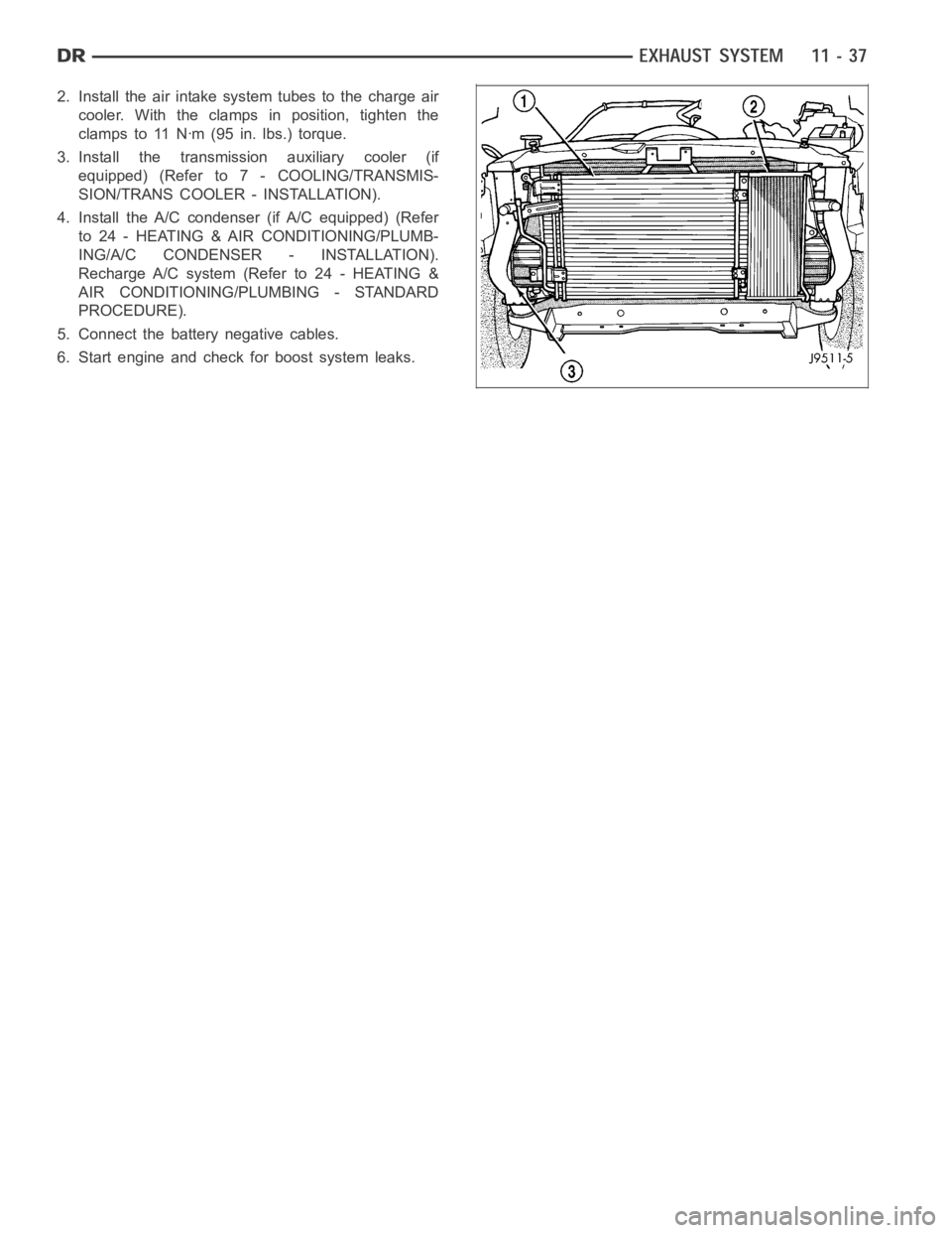
2. Install the air intake system tubes to the charge air
cooler. With the clamps in position, tighten the
clamps to 11 Nꞏm (95 in. lbs.) torque.
3. Install the transmission auxiliary cooler (if
equipped) (Refer to 7 - COOLING/TRANSMIS-
SION/TRANS COOLER - INSTALLATION).
4. Install the A/C condenser (if A/C equipped) (Refer
to 24 - HEATING & AIR CONDITIONING/PLUMB-
ING/A/C CONDENSER - INSTALLATION).
Recharge A/C system (Refer to 24 - HEATING &
AIR CONDITIONING/PLUMBING - STANDARD
PROCEDURE).
5. Connect the battery negative cables.
6. Start engine and check for boost system leaks.
Page 2192 of 5267
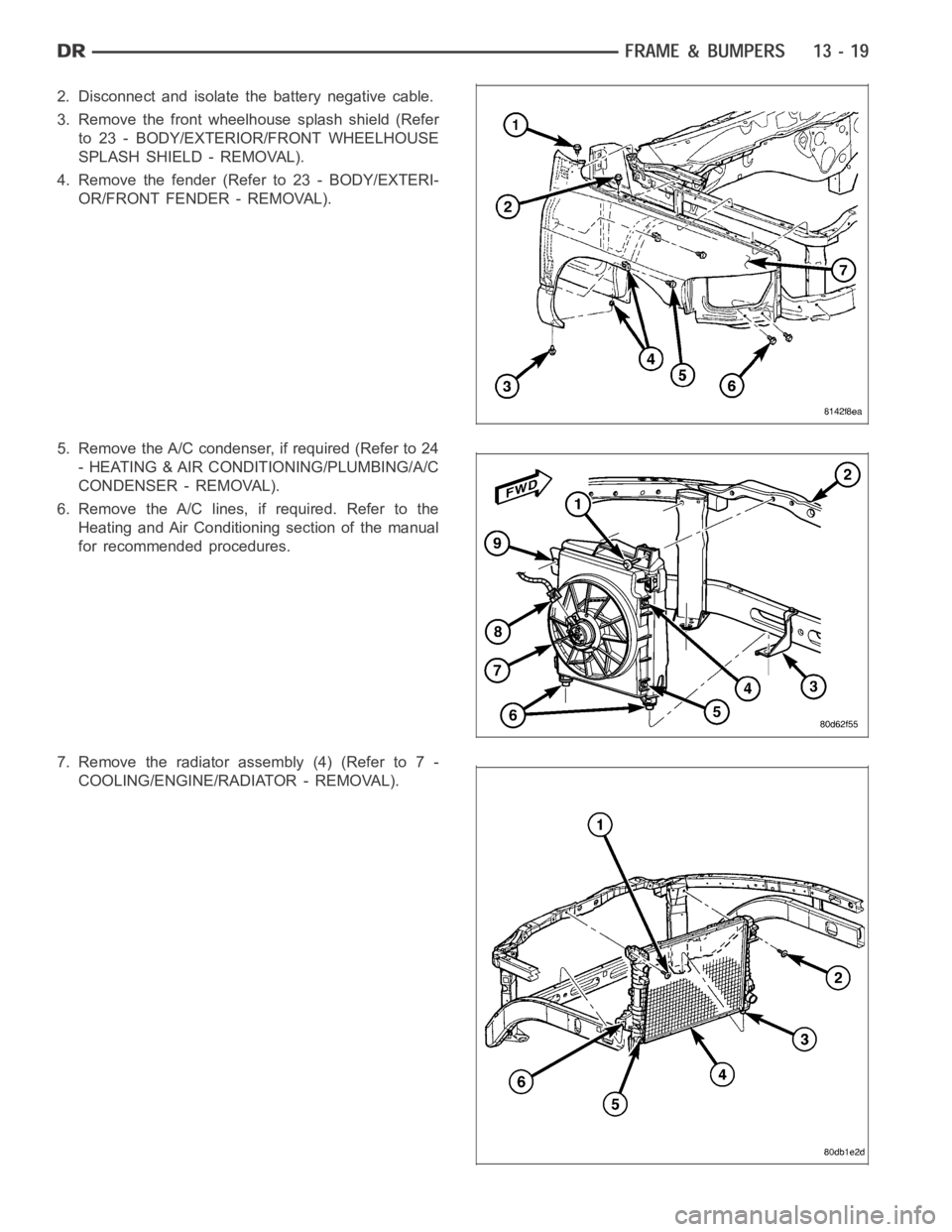
2. Disconnect and isolate the battery negative cable.
3. Remove the front wheelhouse splash shield (Refer
to 23 - BODY/EXTERIOR/FRONT WHEELHOUSE
SPLASH SHIELD - REMOVAL).
4. Remove the fender (Refer to 23 - BODY/EXTERI-
OR/FRONT FENDER - REMOVAL).
5. Remove the A/C condenser, if required (Refer to 24
- HEATING & AIR CONDITIONING/PLUMBING/A/C
CONDENSER - REMOVAL).
6. Remove the A/C lines, if required. Refer to the
Heating and Air Conditioning section of the manual
for recommended procedures.
7. Remove the radiator assembly (4) (Refer to 7 -
COOLING/ENGINE/RADIATOR - REMOVAL).
Page 2200 of 5267
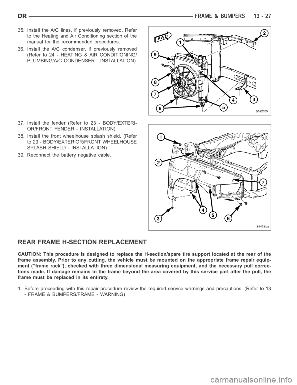
35. Install the A/C lines, if previously removed. Refer
to the Heating and Air Conditioning section of the
manual for the recommended procedures.
36. Install the A/C condenser, if previously removed
(Refer to 24 - HEATING & AIR CONDITIONING/
PLUMBING/A/C CONDENSER - INSTALLATION).
37. Install the fender (Refer to 23 - BODY/EXTERI-
OR/FRONT FENDER - INSTALLATION).
38. Install the front wheelhouse splash shield. (Refer
to 23 - BODY/EXTERIOR/FRONT WHEELHOUSE
SPLASH SHIELD - INSTALLATION)
39. Reconnect the battery negative cable.
REAR FRAME H-SECTION REPLACEMENT
CAUTION: This procedure is designed to replace the H-section/spare tire support located at the rear of the
frame assembly. Prior to any cutting, the vehicle must be mounted on the appropriate frame repair equip-
ment (“frame rack”), checked with three dimensional measuring equipment, and the necessary pull correc-
tions made. If damage remains in the frame beyond the area covered by this service part after the pull, the
frame must be replaced in its entirety.
1. Before proceeding with this repair procedure review the required service warnings and precautions. (Refer to 13
- FRAME & BUMPERS/FRAME - WARNING)
Page 4842 of 5267
HEATING & AIR CONDITIONING
TABLE OF CONTENTS
page page
page page
HVAC - ELECTRICAL DIAGNOSTICS
DIAGNOSIS AND TESTING
B10AA–RIGHT BLEND DOOR CONTROL
CIRCUIT LOW (DUAL-ZONE).................. 4
B10AB–RIGHT BLEND DOOR CONTROL
CIRCUIT HIGH (DUAL-ZONE)................. 8
B10AC–RIGHT BLEND DOOR CONTROL
CIRCUIT OPEN (DUAL-ZONE)................ 11
B10AD–RIGHT BLEND DOOR TRAVEL
RANGE TOO SMALL (DUAL-ZONE)........... 14
B10AE–RIGHT BLEND DOOR TRAVEL
RANGE TOO LARGE (DUAL-ZONE).......... 16
B10A2–LEFT BLEND DOOR CONTROL
CIRCUIT/PERFORMANCE (DUAL-ZONE)...... 18
B10A3–LEFT BLEND DOOR CONTROL
CIRCUIT LOW (DUAL-ZONE)................. 19
B10A4–LEFT BLEND DOOR CONTROL
CIRCUIT HIGH (DUAL-ZONE)................ 23
B10A5–LEFT BLEND DOOR CONTROL
CIRCUIT OPEN (DUAL-ZONE)................ 26
B10A6–LEFT BLEND DOOR TRAVEL
RANGE TOO SMALL (DUAL-ZONE)........... 29
B10A7–LEFT BLEND DOOR TRAVEL
RANGE TOO LARGE (DUAL-ZONE).......... 31
B10A9–RIGHT BLEND DOOR CONTROL
CIRCUIT/PERFORMANCE (DUAL-ZONE)...... 33
B10BE–CONDENSER FAN CONTROL
CIRCUIT LOW (TIPM)....................... 34
B10BF–CONDENSER FAN CONTROL
CIRCUIT HIGH (TIPM)....................... 37
B10B2–A/C COOL DOWN TEST
PERFORMANCE (DUAL-ZONE).............. 40
B10C0–CONDENSER FAN CONTROL
CIRCUIT OPEN (TIPM)...................... 42
B10EC–BLOWER MOTOR CONTROL
CIRCUIT OVERCURRENT (TIPM)............. 45B10EE–CONDENSER FAN CONTROL
CIRCUIT OVERCURRENT (TIPM)............. 50
B10E9–BLOWER MOTOR CONTROL
CIRCUIT LOW (TIPM)....................... 54
B104A–FLOOR/DEFROST MODE DOOR
TRAVEL RANGE TOO SMALL................ 57
B104B–FLOOR/DEFROST MODE DOOR
TRAVEL RANGE TOO LARGE................ 59
B104C–BLEND DOOR CONTROL CIRCUIT/
PERFORMANCE (SINGLE-ZONE)............ 61
B104D–BLEND DOOR CONTROL CIRCUIT
LOW (SINGLE-ZONE)....................... 62
B104E–BLEND DOOR CONTROL CIRCUIT
HIGH (SINGLE-ZONE)....................... 66
B104F–BLEND DOOR CONTROL CIRCUIT
OPEN (SINGLE-ZONE)...................... 69
B105A–RECIRCULATION DOOR CONTROL
CIRCUIT HIGH (DUAL-ZONE)................ 72
B105A–RECIRCULATION DOOR CONTROL
CIRCUIT HIGH (SINGLE-ZONE).............. 75
B105B–RECIRCULATION DOOR CONTROL
CIRCUIT OPEN (DUAL-ZONE)................ 78
B105B–RECIRCULATION DOOR CONTROL
CIRCUIT OPEN (SINGLE-ZONE).............. 81
B105C–RECIRCULATION DOOR TRAVEL
RANGE TOO SMALL........................ 84
B105D–RECIRCULATION DOOR TRAVEL
RANGE TOO LARGE........................ 86
B105F–CLIMATE CONTROL MOTOR(S)
COMMON 1 CONTROL CIRCUIT LOW
(DUAL-ZONE)............................... 88
B105F–CLIMATE CONTROL MOTOR(S)
COMMON 1 CONTROL CIRCUIT LOW
(SINGLE-ZONE)............................. 96
B1001–A/C SWITCH REQUEST INPUT
CIRCUIT LOW (SINGLE-ZONE).............. 103
Page 5046 of 5267
*HVAC SYSTEM TEST
For a complete wiring diagramRefer to Section 8W.
Theory of Operation
The HVAC System Test provides a starting point in the diagnostic process byidentifying the appropriate diagnostic
procedure or system test to perform when diagnosing a given symptom, condition, or DTC. It also provides a means
for testing the entire HVAC system byutilizing the A/C-heater control’s On-Board System Tests. The On-Board Sys-
tem Tests can also assist in diagnosing stored DTCs. (Refer to 24 - HEATING &AIR CONDITIONING - DIAGNOSIS
AND TESTING) for additional information about on-board diagnostics.
Diagnostic Test
1.HVAC SYSTEM TEST
NOTE: Diagnose and repair all active DTCs before diagnosing and repairingstored DTCs.
Make a selection based on the symptom, condition, or DTC that you want to diagnose.
For Any Active DTC
Refer to the Table of Contents in this Section for a complete list of HVAC related symptoms.
Scan Tool Indicates HVAC Not Active On Bus
(Refer to 8 - ELECTRICAL/ELECTRONIC CONTROL MODULES - DIAGNOSIS AND TESTING) for no
response related diagnostic procedures.
Blower Motor Inoperative
Refer to *Blower Motor Inoperative in this Section.
Complete HVAC System Test
Go To 2
A/C System Performance Test
Go To 2
Mode Switch & Door Actuator Ckt Test
Go To 3
Actuator DTC Detection Test
Go To 4
Actuator Calibration Test
Go To 5
2.A/C SYSTEM PERFORMANCE TEST
NOTE: The following are prerequisites of the Cooldown Test. Verify each ofthe following before running the
test:
If active, diagnose and repair Evaporator Temperature Sensor related DTCs before proceeding. Refer to
the Table of Contents in this Section for a complete list of HVAC related symptoms.
Verify that the refrigerant system has an adequate charge. Check and repair as necessary before pro-
ceeding. (Refer to 24 - HEATING & AIR CONDITIONING/PLUMBING - DIAGNOSIS ANDTESTING).
Verify that the blower motor operates correctly in all speeds. Diagnose and repair all blower related faults
before proceeding.
Verify that the work area ambient temperature is above 15.6°C (60°F) before proceeding. Move the vehicle
to a warmer work area if necessary.
Verify that the evaporator temperature is above 13°C (55°F) before proceeding.
Verify that the Mode Select control is set to the panel position.
Verify that the A/C compressor is not running. If the compressor is running, turn the A/C off and allow the
evaporator to warm up before proceeding.
NOTE: Running the AC Cooldown test will cause the A/C status indicator to flash.
NOTE: One or more status messages will display on the scan tool after running the Cooldown Test. These
messages will clear after paging back out of this test function. Therefore, it is important to note all mes-
sages before doing so.
Start the engine.
Turn the Blower control to the high speed position.
Page 5050 of 5267
HVAC - SERVICE INFORMATION
DESCRIPTION
A manually controlled single zone type heating-air conditioning system or a manually controlleddualzonetypeheat-
ing-air conditioning system is available on this model.
To maintain the performance level of the heating, ventilation and air conditioning (HVAC) system, the engine cooling
system must be properly maintained. The use of a bug screen is not recommended. Any obstructions in front of the
radiator or A/C condenser will reduce the performance of the A/C and enginecooling systems.
The engine cooling system includes the radiator, thermostat, radiator hoses and the engine coolant pump. Refer to
7 - Cooling for more information before opening or attempting any service to the engine cooling system.
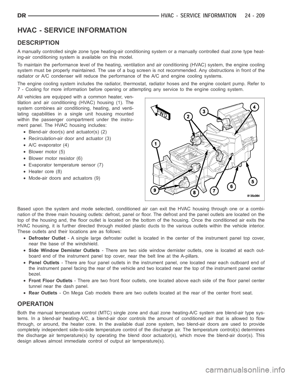
All vehicles are equipped with a common heater, ven-
tilation and air conditioning (HVAC) housing (1). The
system combines air conditioning, heating, and venti-
lating capabilities in a single unit housing mounted
within the passenger compartment under the instru-
ment panel. The HVAC housing includes:
Blend-air door(s) and actuator(s) (2)
Recirculation-air door and actuator (3)
A/C evaporator (4)
Blower motor (5)
Blower motor resistor (6)
Evaporator temperature sensor (7)
Heater core (8)
Mode-air doors and actuators (9)
Based upon the system and mode selected, conditioned air can exit the HVAC housing through one or a combi-
nation of the three main housing outlets: defrost, panel or floor. The defrost and the panel outlets are located on the
top of the housing and, the floor outlet is located on the bottom of the housing. Once the conditioned air exits the
HVAC housing, it is further directed through molded plastic ducts to the various outlets within the vehicle interior.
These outlets and their locations are as follows:
Defroster Outlet- A single large defroster outlet is located in the center of the instrumentpanel top cover,
near the base of the windshield.
Side Window Demister Outlets- There are two side window demister outlets, one is located at each out-
board end of the instrument panel top cover, near the belt line at the A-pillars.
Panel Outlets- There are four panel outlets in the instrument panel, one located near each outboard end of
the instrument panel facing the rear of the vehicle and two located near thetop of the instrument panel center
bezel.
Front Floor Outlets- There are two front floor outlets, one located above each side of the floorpanel center
tunnel near the dash panel.
Rear Outlets- On Mega Cab models there are two outlets located at the rear of the center front seat.
OPERATION
Both the manual temperature control (MTC) single zone and dual zone heating-A/C system are blend-air type sys-
tems. In a blend-air heating-A/C, a blend-air door controls the amount of conditioned air that is allowed to flow
through, or around, the heater core.In the available dual zone system, twoblend-air doors are used to provide
completely independent side-to-side temperature control of the discharge air. The temperature control(s) determines
the discharge air temperature(s) by operating the blend door actuator(s), which move the blend-air door(s). This
design allows almost immediate control of output air temperature(s).
Page 5051 of 5267
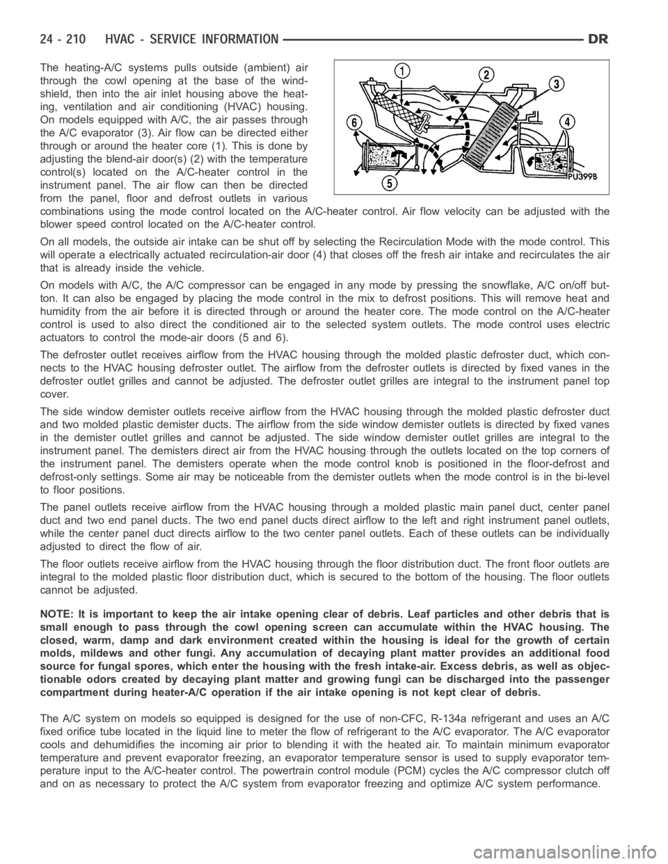
The heating-A/C systems pulls outside (ambient) air
through the cowl opening at the base of the wind-
shield, then into the air inlet housing above the heat-
ing, ventilation and air conditioning (HVAC) housing.
On models equipped with A/C, the air passes through
the A/C evaporator (3). Air flow can be directed either
through or around the heater core (1). This is done by
adjusting the blend-air door(s) (2) with the temperature
control(s) located on the A/C-heater control in the
instrument panel. The air flow can then be directed
from the panel, floor and defrost outlets in various
combinations using the mode control located on the A/C-heater control. Air flow velocity can be adjusted with the
blower speed control located on the A/C-heater control.
On all models, the outside air intake can be shut off by selecting the Recirculation Mode with the mode control. This
will operate a electrically actuated recirculation-air door (4) that closes off the fresh air intake and recirculates the air
that is already inside the vehicle.
On models with A/C, the A/C compressor can be engaged in any mode by pressingthe snowflake, A/C on/off but-
ton. It can also be engaged by placing the mode control in the mix to defrost positions. This will remove heat and
humidity from the air before it is directed through or around the heater core. The mode control on the A/C-heater
control is used to also direct the conditioned air to the selected system outlets. The mode control uses electric
actuators to control the mode-air doors (5 and 6).
The defroster outlet receives airflow from the HVAC housing through the molded plastic defroster duct, which con-
nects to the HVAC housing defroster outlet. The airflow from the defrosteroutlets is directed by fixed vanes in the
defroster outlet grilles and cannot be adjusted. The defroster outlet grilles are integral to the instrument panel top
cover.
The side window demister outlets receive airflow from the HVAC housing through the molded plastic defroster duct
and two molded plastic demister ducts. The airflow from the side window demister outlets is directed by fixed vanes
in the demister outlet grilles and cannot be adjusted. The side window demister outlet grilles are integral to the
instrument panel. The demisters direct air from the HVAC housing through the outlets located on the top corners of
the instrument panel. The demisters operate when the mode control knob is positioned in the floor-defrost and
defrost-only settings. Some air may be noticeable from the demister outlets when the mode control is in the bi-level
to floor positions.
The panel outlets receive airflow from the HVAC housing through a molded plastic main panel duct, center panel
duct and two end panel ducts. The two end panel ducts direct airflow to the left and right instrument panel outlets,
while the center panel duct directs airflow to the two center panel outlets. Each of these outlets can be individually
adjusted to direct the flow of air.
The floor outlets receive airflow from the HVAC housing through the floor distribution duct. The front floor outlets are
integral to the molded plastic floor distribution duct, which is secured to the bottom of the housing. The floor outlets
cannot be adjusted.
NOTE: It is important to keep the air intake opening clear of debris. Leaf particles and other debris that is
small enough to pass through the cowl opening screen can accumulate withinthe HVAC housing. The
closed, warm, damp and dark environment created within the housing is ideal for the growth of certain
molds, mildews and other fungi. Any accumulation of decaying plant matterprovides an additional food
source for fungal spores, which enter the housing with the fresh intake-air. Excess debris, as well as objec-
tionable odors created by decaying plant matter and growing fungi can be discharged into the passenger
compartment during heater-A/C operation if the air intake opening is not kept clear of debris.
The A/C system on models so equipped is designed for the use of non-CFC, R-134a refrigerant and uses an A/C
fixedorificetubelocatedintheliquidlinetometertheflowofrefrigerant to the A/C evaporator. The A/C evaporator
cools and dehumidifies the incoming air prior to blending it with the heated air. To maintain minimum evaporator
temperature and prevent evaporator freezing, an evaporator temperaturesensor is used to supply evaporator tem-
perature input to the A/C-heater control. The powertrain control module (PCM) cycles the A/C compressor clutch off
and on as necessary to protect the A/C system from evaporator freezing and optimize A/C system performance.
Page 5053 of 5267
ACTUATOR DTC DETECTION TEST — DUAL-ZONE
The Actuator DTC Detection Test:
is actuated with a scan tool.
clears all actuator related DTCs when the test is actuated.
supplements the continuous diagnostics on the actuator drive system.
monitors for shorted actuator circuits allowing service to easily diagnose and troubleshoot up to three simul-
taneous shorts. Shorted actuator circuit faults (XXX Control Circuit High or XXX Control Circuit Low) will only
display after running the Actuator DTC Detection Test.
After repairing each DTC, cycle the ignition switch, and then run the Actuator DTC Detection Test again to ensure
that no new DTCs exist. If multiple DTCs are present, beginning with the passenger blend door, diagnose and repair
all short high faults and then short low faults. When the test returns passed, clear all faults and run the Actuator
Calibration function as a final check of system health.
ACTUATOR DTC DETECTION TEST — SINGLE-ZONE
The Actuator DTC Detection Test:
is actuated with a scan tool.
clears all actuator related DTCs when the test is actuated.
supplements the continuous diagnostics on the actuator drive system.
monitors for shorted actuator circuits allowing service to easily diagnose and troubleshoot up to three simul-
taneous shorts. Shorted actuator circuit faults (XXX Control Circuit High or XXX Control Circuit Low) will only
display after running the Actuator DTC Detection Test.
After repairing each DTC, cycle the ignition switch, and then run the Actuator DTC Detection Test again to ensure
that no new DTCs exist. If multiple DTCs are present, beginning with the common circuit, diagnose and repair all
short high faults and then short low faults. When the test returns passed, clear all faults and run the Actuator Cal-
ibration function as a final check of system health.
A/C PERFORMANCE
The A/C system is designed to provide the passenger compartment with low temperature and low humidity air. The
A/C evaporator, located in the HVAC housing is cooled to temperatures nearthe freezing point. As warm damp air
passes over the fins of the A/C evaporator, the air transfers its heat to therefrigerant in the evaporator coils and the
moisture in the air condenses on the evaporator fins. During periods of high heat and humidity, an A/C system will
be more effective in the Recirculation mode (max-A/C). With the system in the Recirculation mode, only air from the
passenger compartment passes through the A/C evaporator. As the passenger compartment air dehumidifies, the
A/C system performance levels rise.
Humidity has an important bearing on the temperature of the air delivered to the interior of the vehicle. It is impor-
tant to understand the effect that humidity has on the performance of the A/C system. When humidity is high, the
A/C evaporator has to perform a double duty. It must lower the air temperature, and it must lower the temperature
of the moisture in the air that condenses on the evaporator fins. Condensing the moisture in the air transfers heat
energy into the evaporator fins and coils. This reduces the amount of heat the A/C evaporator can absorb from the
air. High humidity greatly reduces the ability of the A/C evaporator to lower the temperature of the air.
However, evaporator capacity used to reduce the amount of moisture in the air is not wasted. Wringing some of the
moisture out of the air entering the vehicle adds to the comfort of the passengers. Although, an owner may expect
too much from their A/C system on humid days. A performance test is the best way to determine whether the sys-
tem is performing up to design standards. This test also provides valuableclues as to the possible cause of trouble
with the A/C system. The ambient air temperature in the location where the vehicle will be tested must be a mini-
mum of 21° C (70° F) for this test.
A/C PERFORMANCE TEST
WARNING: Refer to the applicable warnings and cautions for this system before performing the following
operation (Refer to 24 - HEATING & AIR CONDITIONING/PLUMBING - WARNINGS) and (Refer to 24 - HEAT-
ING & AIR CONDITIONING/PLUMBING - CAUTIONS). Failure to follow the warnings and cautions could result
in possible personal injury or death.