Page 1776 of 5267
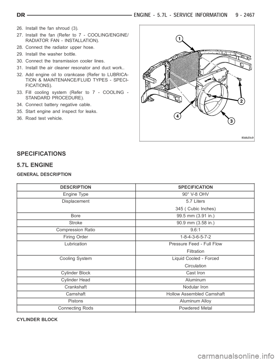
26. Install the fan shroud (3).
27. Install the fan (Refer to 7 - COOLING/ENGINE/
RADIATOR FAN - INSTALLATION).
28. Connect the radiator upper hose.
29. Install the washer bottle.
30. Connect the transmission cooler lines.
31. Install the air cleaner resonator and duct work..
32. Add engine oil to crankcase (Refer to LUBRICA-
TION & MAINTENANCE/FLUID TYPES - SPECI-
FICATIONS).
33. Fill cooling system (Refer to 7 - COOLING -
STANDARD PROCEDURE).
34. Connect battery negative cable.
35. Start engine and inspect for leaks.
36. Road test vehicle.
SPECIFICATIONS
5.7L ENGINE
GENERAL DESCRIPTION
DESCRIPTION SPECIFICATION
Engine Type 90° V-8 OHV
Displacement 5.7 Liters
345 ( Cubic Inches)
Bore 99.5 mm (3.91 in.)
Stroke 90.9 mm (3.58 in.)
Compression Ratio 9.6:1
Firing Order 1-8-4-3-6-5-7-2
Lubrication Pressure Feed - Full Flow
Filtration
Cooling System Liquid Cooled - Forced
Circulation
Cylinder Block Cast Iron
Cylinder Head Aluminum
Crankshaft Nodular Iron
Camshaft Hollow Assembled Camshaft
Pistons Aluminum Alloy
Connecting Rods Powdered Metal
CYLINDER BLOCK
Page 1777 of 5267
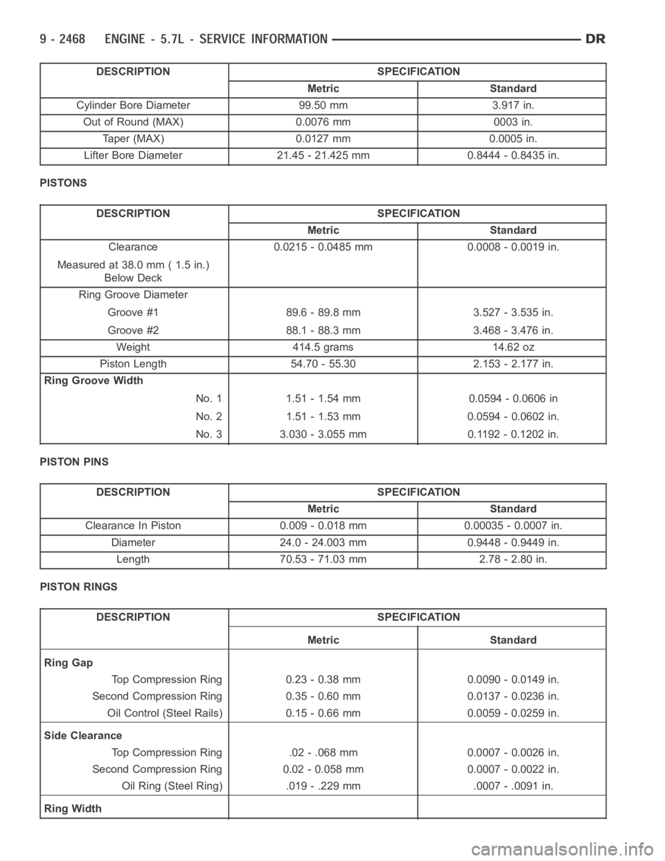
DESCRIPTION SPECIFICATION
Metric Standard
Cylinder Bore Diameter 99.50 mm 3.917 in.
Out of Round (MAX) 0.0076 mm 0003 in.
Taper (MAX) 0.0127 mm 0.0005 in.
Lifter Bore Diameter 21.45 - 21.425 mm 0.8444 - 0.8435 in.
PISTONS
DESCRIPTION SPECIFICATION
Metric Standard
Clearance 0.0215 - 0.0485 mm 0.0008 - 0.0019 in.
Measured at 38.0 mm ( 1.5 in.)
Below Deck
Ring Groove Diameter
Groove #1 89.6 - 89.8 mm 3.527 - 3.535 in.
Groove #2 88.1 - 88.3 mm 3.468 - 3.476 in.
Weight 414.5 grams 14.62 oz
Piston Length 54.70 - 55.30 2.153 - 2.177 in.
Ring Groove Width
No. 1 1.51 - 1.54 mm 0.0594 - 0.0606 in
No. 2 1.51 - 1.53 mm 0.0594 - 0.0602 in.
No. 3 3.030 - 3.055 mm 0.1192 - 0.1202 in.
PISTON PINS
DESCRIPTION SPECIFICATION
Metric Standard
Clearance In Piston 0.009 - 0.018 mm 0.00035 - 0.0007 in.
Diameter 24.0 - 24.003 mm 0.9448 - 0.9449 in.
Length 70.53 - 71.03 mm 2.78 - 2.80 in.
PISTON RINGS
DESCRIPTION SPECIFICATION
Metric Standard
Ring Gap
Top Compression Ring 0.23 - 0.38 mm 0.0090 - 0.0149 in.
Second Compression Ring 0.35 - 0.60 mm 0.0137 - 0.0236 in.
Oil Control (Steel Rails) 0.15 - 0.66 mm 0.0059 - 0.0259 in.
Side Clearance
Top Compression Ring .02 - .068 mm 0.0007 - 0.0026 in.
Second Compression Ring 0.02 - 0.058 mm 0.0007 - 0.0022 in.
Oil Ring (Steel Ring) .019 - .229 mm .0007 - .0091 in.
Ring Width
Page 1778 of 5267
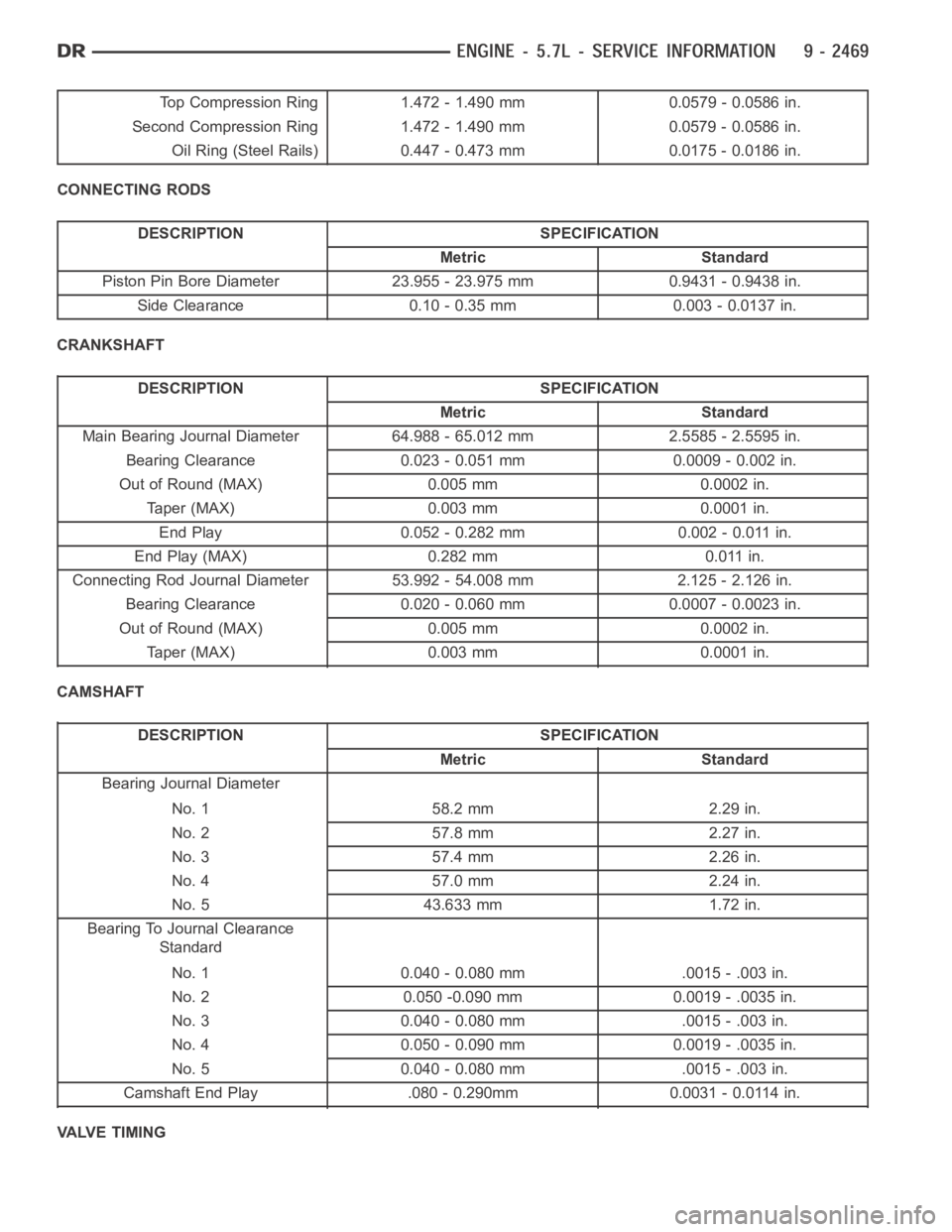
Top Compression Ring 1.472 - 1.490 mm 0.0579 - 0.0586 in.
Second Compression Ring 1.472 - 1.490 mm 0.0579 - 0.0586 in.
Oil Ring (Steel Rails) 0.447 - 0.473 mm 0.0175 - 0.0186 in.
CONNECTING RODS
DESCRIPTION SPECIFICATION
Metric Standard
Piston Pin Bore Diameter 23.955 - 23.975 mm 0.9431 - 0.9438 in.
Side Clearance 0.10 - 0.35 mm 0.003 - 0.0137 in.
CRANKSHAFT
DESCRIPTION SPECIFICATION
Metric Standard
Main Bearing Journal Diameter 64.988 - 65.012 mm 2.5585 - 2.5595 in.
Bearing Clearance 0.023 - 0.051 mm 0.0009 - 0.002 in.
Out of Round (MAX) 0.005 mm 0.0002 in.
Taper (MAX) 0.003 mm 0.0001 in.
End Play 0.052 - 0.282 mm 0.002 - 0.011 in.
End Play (MAX) 0.282 mm 0.011 in.
Connecting Rod Journal Diameter 53.992 - 54.008 mm 2.125 - 2.126 in.
Bearing Clearance 0.020 - 0.060 mm 0.0007 - 0.0023 in.
Out of Round (MAX) 0.005 mm 0.0002 in.
Taper (MAX) 0.003 mm 0.0001 in.
CAMSHAFT
DESCRIPTION SPECIFICATION
Metric Standard
Bearing Journal Diameter
No. 1 58.2 mm 2.29 in.
No. 2 57.8 mm 2.27 in.
No. 3 57.4 mm 2.26 in.
No. 4 57.0 mm 2.24 in.
No. 5 43.633 mm 1.72 in.
Bearing To Journal Clearance
Standard
No. 1 0.040 - 0.080 mm .0015 - .003 in.
No. 2 0.050 -0.090 mm 0.0019 - .0035 in.
No. 3 0.040 - 0.080 mm .0015 - .003 in.
No. 4 0.050 - 0.090 mm 0.0019 - .0035 in.
No. 5 0.040 - 0.080 mm .0015 - .003 in.
Camshaft End Play .080 - 0.290mm 0.0031 - 0.0114 in.
VALVE TIMING
Page 1780 of 5267
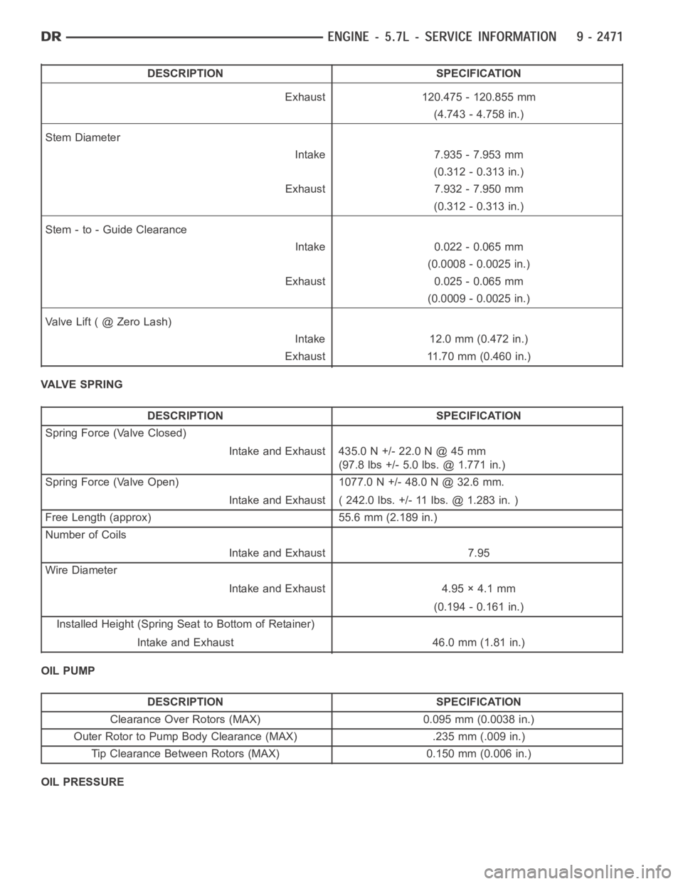
DESCRIPTION SPECIFICATION
Exhaust 120.475 - 120.855 mm
(4.743 - 4.758 in.)
Stem Diameter
Intake 7.935 - 7.953 mm
(0.312 - 0.313 in.)
Exhaust 7.932 - 7.950 mm
(0.312 - 0.313 in.)
Stem - to - Guide Clearance
Intake 0.022 - 0.065 mm
(0.0008 - 0.0025 in.)
Exhaust 0.025 - 0.065 mm
(0.0009 - 0.0025 in.)
ValveLift(@ZeroLash)
Intake 12.0 mm (0.472 in.)
Exhaust 11.70 mm (0.460 in.)
VALVE SPRING
DESCRIPTION SPECIFICATION
Spring Force (Valve Closed)
Intake and Exhaust 435.0 N +/- 22.0 N @ 45 mm
(97.8 lbs +/- 5.0 lbs. @ 1.771 in.)
Spring Force (Valve Open) 1077.0 N +/- 48.0 N @ 32.6 mm.
Intake and Exhaust ( 242.0 lbs. +/- 11 lbs. @ 1.283 in. )
Free Length (approx) 55.6 mm (2.189 in.)
Number of Coils
Intake and Exhaust 7.95
Wire Diameter
Intake and Exhaust 4.95 × 4.1 mm
(0.194 - 0.161 in.)
Installed Height (Spring Seat to Bottom of Retainer)
Intake and Exhaust 46.0 mm (1.81 in.)
OIL PUMP
DESCRIPTION SPECIFICATION
Clearance Over Rotors (MAX) 0.095 mm (0.0038 in.)
Outer Rotor to Pump Body Clearance (MAX) .235 mm (.009 in.)
Tip Clearance Between Rotors (MAX) 0.150 mm (0.006 in.)
OIL PRESSURE
Page 1781 of 5267
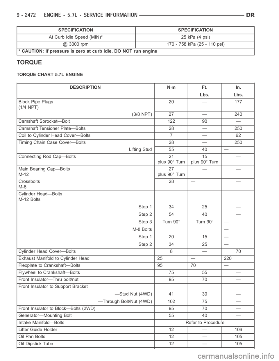
SPECIFICATION SPECIFICATION
At Curb Idle Speed (MIN)* 25 kPa (4 psi)
@ 3000 rpm 170 - 758 kPa (25 - 110 psi)
* CAUTION: If pressure is zero at curb idle, DO NOT run engine
TORQUE
TORQUE CHART 5.7L ENGINE
DESCRIPTION Nꞏm Ft. In.
Lbs. Lbs.
Block Pipe Plugs
(1/4 NPT)20 — 177
(3/8 NPT) 27 — 240
Camshaft Sprocket—Bolt 122 90 —
Camshaft Tensioner Plate—Bolts 28 — 250
Coil to Cylinder Head Cover—Bolts 7 — 62
Timing Chain Case Cover—Bolts 28 — 250
Lifting Stud 55 40 —
Connecting Rod Cap—Bolts 21
plus 90° Turn15
plus 90° Turn—
Main Bearing Cap—Bolts
M-1227
plus 90° Turn——
Crossbolts
M-828 — —
Cylinder Head—Bolts
M-12 Bolts
Step 1 34 25 —
Step 2 54 40 —
Step 3 Turn 90° Turn 90° —
M-8 Bolts —
Step 1 20 15 —
Step 2 34 25 —
Cylinder Head Cover—Bolts 8 — 70
Exhaust Manifold to Cylinder Head 25 — 220
Flexplate to Crankshaft—Bolts 95 70 —
Flywheel to Crankshaft—Bolts 75 55 —
Front Insulator—Thru bolt/nut 95 70 —
Front Insulator to Support Bracket
—Stud Nut (4WD) 41 30 —
—Through Bolt/Nut (4WD) 102 75 —
Front Insulator to Block—Bolts (2WD) 95 70 —
Generator—Mounting Bolt 55 40 —
Intake Manifold—Bolts Refer to Procedure
Lifter Guide Holder 12 — 106
Oil Pan Bolts 12 — 105
Oil Dipstick Tube 12 — 105
Page 1782 of 5267
DESCRIPTION Nꞏm Ft. In.
Oil Pan—Drain Plug 34 25 —
Oil Pump—Attaching Bolts 28 — 250
Oil Pump Pickup Tube – Bolt and Nut 28 — 250
Rear Seal Retainer Attaching Bolts 15 — 132
Rear Insulator to Bracket— 68 50 —
Through-Bolt (2WD)
Rear Insulator to Crossmember 41 30 —
Support Bracket—Nut (2WD)
Rear Insulator to Crossmember— 68 50 —
Nuts (4WD)
Rear Insulator to Transmission— 68 50 —
Bolts (4WD)
Rear Insulator Bracket—Bolts 68 50 —
(4WD Automatic)
Rear Support Bracket to 41 30 —
Crossmember Flange—Nuts
Rear Support Plate to Transfer 41 30 —
Case—Bolts
Rocker Arm—Bolts 22 — 195
Spark Plugs — — —
Thermostat Housing—Bolts 28 — 250
Throttle Body—Bolts 12 — 105
Transfer Case to Insulator 204 105 —
Mounting Plate—Nuts
Transmission Support Bracket— 68 50 —
Bolts (2WD)
Vibration Damper—Bolt 176 129 —
Water Pump to Timing Chain 28 — 250
Case Cover—Bolts
Page 1785 of 5267
Oil Pressure Gauge C-3292
Piston Ring Compressor C-385
Pressure Tester Kit 7700
Rear Crankshaft Seal Installer 8349
Rear Crankshaft Seal Remover 8506
Valve Spring Compressor C-3422-B
Valve Spring Tester C-647
Adapter, Valve Spring Compressor Off-vehicle 8464
Page 1799 of 5267
COVER - CYLINDER HEAD
REMOVAL
1. Disconnect battery negative cable.
2. Disconnect ignition coil connector (1).
3. Remove ignition coil retaining bolts (3).
4. Remove ignition coil (1).