Page 1858 of 5267
INSTALLATION
1. Before installing piston and connecting rod assemblies into the bore, install the piston rings (Refer to 9 -
ENGINE/ENGINE BLOCK/PISTON RINGS - STANDARD PROCEDURE).
2. Immerse the piston head and rings in clean engine oil. Position a ring compressor over the piston and rings.
Tighten ring compressor.Ensure position of rings do not change during this operation.
3. Position bearing onto connecting rod. Lubricate bearing surface with clean engine oil.
4. Install Special Tool 8507 Connecting Rod Guides into connecting rod bolt threads.
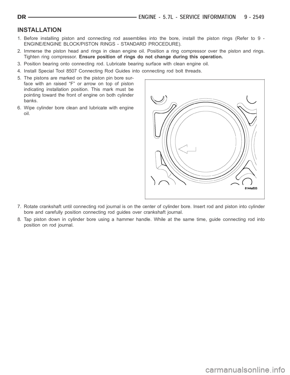
5. The pistons are marked on the piston pin bore sur-
face with an raised “F” or arrow on top of piston
indicating installation position. This mark must be
pointing toward the front of engine on both cylinder
banks.
6. Wipe cylinder bore clean and lubricate with engine
oil.
7. Rotate crankshaft until connecting rod journal is on the center of cylinder bore. Insert rod and piston into cylinder
bore and carefully position connecting rod guides over crankshaft journal.
8. Tap piston down in cylinder bore using a hammer handle. While at the same time, guide connecting rod into
position on rod journal.
Page 1859 of 5267
CAUTION: Connecting Rod Bolts are Torque to Yield Bolts and Must Not Be Reused. Always replace the
Rod Bolts whenever they are loosened or removed.
9. Lubricate rod bolts and bearing surfaces with engine oil. Install connecting rod cap and bearing. Tighten bolts to
21 Nꞏm (15 ft. lbs.) plus a 90° turn.
10. Install the following components:
Cylinder head(s). (Refer to 9 - ENGINE/CYLINDER HEAD - INSTALLATION).
Cylinderheadcovers(Referto9-ENGINE/CYLINDER HEAD/CYLINDER HEAD COVER(S) - INSTALLA-
TION).
Install the intake manifold.
Oil pan and gasket/windage tray. (Refer to 9 - ENGINE/LUBRICATION/OIL PAN- INSTALLATION).
11. Fill crankcase with proper engine oil to correct level.
12. Connect negative cable to battery.
Page 1861 of 5267
Ring Position Ring/Groove Maximum
Ring Position Ring Gap Wear Limit
Upper Ring 0.23-0.38mm 0.43mm
(0.0090-0.0149 in.) (0.017 in.)
Intermediate Ring 0.35-0.60mm 0.74mm
(0.0137-0.0236 in.) (0.029 in.)
Oil Control Ring 0.015-0.66mm 0.76mm
(Steel Rail) (0.0059- 0.0259 in.) (0.030 in.)
7. The No. 1 and No. 2 piston rings have a different cross section. Ensure No.2 ring is installed with manufacturers
I.D. mark (Dot) facing up, towards top of the piston.
NOTE: Piston rings are installed in the following order:
Oil ring expander.
Lower oil ring side rail.
Upper oil ring side rail.
No. 2 Intermediate piston ring.
No. 1 Upper piston ring.
8. Install the oil ring expander.
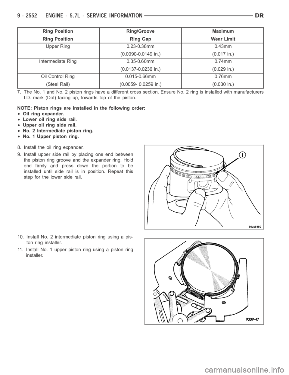
9. Install upper side rail by placing one end between
the piston ring groove and the expander ring. Hold
end firmly and press down the portion to be
installed until side rail is in position. Repeat this
step for the lower side rail.
10. Install No. 2 intermediate piston ring using a pis-
ton ring installer.
11. Install No. 1 upper piston ring using a piston ring
installer.
Page 1868 of 5267
SOLENOID-MDS
DESCRIPTION
The Multi Displacement System selectively deactivates cylinders 1,4,6,and 7, to improve fuel economy. It has two
modes of operation :
8 cylinders for acceleraton and heavy loads.
4 cylinders for cruising and city traffic.
The main components of the Multi Displacement System are :
Unique MDS camshaft.
Deactivating roller tappets.
4 control valves/solenoids.
control valve/solenoid wiring harness.
oil temp sensor.
OPERATION
Cylinder Deactivation
Trap an exhaust charge from a normal combustion event
Normal combustion event
Don’t open the exhaust valve
Don’t open the intake valve
Piston is an air spring
Cylinders deactivated in firing sequence
Cylinder Reactivation
Open the exhaust valve
Empty the cylinder
Open the intake valve
Normal combustion event
Cylinders reactivated in firing sequence
DIAGNOSIS AND TESTING
The Multi Displacement System has the following detectible issues:
Solenoid circuit
Fail to deactivate a cylinder(s)
Fail to reactivate a cylinder(s)
Low oil pressure
CONDITION POSSIBLE CAUSES CORRECTION
MDS does not activate 1. Low oil pressure 1. Check for proper oil pressure
2. Bad oil temp sensor 2. Replace oil temp sensor
3. Malfunctioning MDS Solenoid 3. Replace Solenoid
4. Malfunctioning MDS Tappet 4. Replace Tappet
MDS Does Not Deactivate 1. Low oil pressure 1. Check for proper oil pressure
2. Bad oil temp sensor 2. Replace oil temp sensor
3. Malfunctioning MDS Solenoid 3. Replace Solenoid
4. Malfunctioning MDS Tappet 4. Replace Tappet
Page 1871 of 5267
4WD
1. Disconnect the negative cable from the battery.
2. Raise the vehicle.
3. Removetheskidplate.
4. Remove the front crossmember (Refer to 13 - FRAME & BUMPERS/FRAME/FRONTCROSSMEMBER -
REMOVAL).
5. Remove the engine oil filter.
6. Support the engine using engine support fixture, special tool # 8534.
7. Support the front axle with a suitable jack.
8. Remove the (4) bolts that attach the engine mounts to the front axle.
9. Remove the (3) bolts that attach the front axle to the left engine bracket.
10. Lower the front axle.
11. Remove the (6) through bolts
12. Raise the engine far enough to be able to remove the left (4) and right (8)engine mounts.
13. Remove the engine mounts (4,8).
Page 1873 of 5267
3. Insert the two upper through bolts into the right and left side engine mounts and loose assemble the two nuts
onto the through bolts.
4. Lower the engine using engine support fixture special tool # 8534, untilthe left and right side engine brackets
rest on the through bolts, and the lower engine bracket through holes alignwith the engine mounts, and the left
engine bracket holes align with the front axle slots.
5. Loose assemble the 3 bolts that attach the front axle to the left engine bracket.
6. Loose assemble the lower through bolts.
7. Torque the nuts for the 4 through bolts to 101 Nꞏm (75 ft. lbs.).
8. Torque the 3 bolts that attach the front axle to the left engine bracket to101Nꞏm(75ft.lbs.).
9. Install the engine oil filter, if removed.
10. Install the front crossmember (Refer to 13 - FRAME & BUMPERS/FRAME/FRONT CROSSMEMBER - INSTAL-
LATION).
11. Install the skid plate.
12. Lower the vehicle.
13. Reconnect the negative battery cable.
Page 1875 of 5267
LUBRICATION
DIAGNOSIS AND TESTING
DIAGNOSIS AND TESTING - CHECKING ENGINE OIL PRESSURE
1. Remove oil pressure sending unit and install gauge assembly C-3292.
2. Run engine until thermostat opens.
3. Oil Pressure:
Curb Idle–25 kPa (4 psi) minimum
3000 rpm–170 - 758 kPa (25 - 110 psi)
4. If oil pressure is 0 at idle, shut off engine. Check for a clogged oil pick-up screen or a pressure relief valve stuck
open.
DIAGNOSIS AND TESTING - ENGINE OIL LEAK
Begin with a thorough visual inspection of the engine, particularly at thearea of the suspected leak. If an oil leak
source is not readily identifiable, thefollowingstepsshouldbefollowed:
1. Do not clean or degrease the engine at this time because some solvents maycause rubber to swell, temporarily
stopping the leak.
2. Add an oil soluble dye (use as recommended by manufacturer). Start the engine and let idle for approximately 15
minutes. Check the oil dipstick to make sure the dye is thoroughly mixed as indicated with a bright yellow color
under a black light.
3. Using a black light, inspect the entire engine for fluorescent dye, particularly at the suspected area of oil leak. If
the oil leak is found and identified, repair per service manual instructions.
4. If dye is not observed, drive the vehicle at various speeds for approximately 24 km (15 miles), and repeat inspec-
tion.If the oil leak source is not positively identified at this time, proceed with the air leak detection test
method.
Air Leak Detection Test Method
1. Remove the PCV valve from the IAFM. Cap or plug the PCV valve grommet.
2. Attach an air hose with pressure gauge and regulator to the dipstick tube.
CAUTION: Do not subject the engine assembly to more than 20.6 kPa (3 PSI) of test pressure.
3. Gradually apply air pressure from 1 psi to 2.5 psi maximum while applyingsoapy water at the suspected source.
Adjust the regulator to the suitable test pressure that provide the best bubbles which will pinpoint the leak
source. If the oil leak is detected and identified, repair per service manual procedures.
4. If the leakage occurs at the rear oil seal area, refer to the section, Inspection for Rear Seal Area Leak.
5. If no leaks are detected, turn off the air supply and remove the air hose and all plugs and caps. Install the PCV
valve.
6. Clean the oil off the suspect oil leak area using a suitable solvent. Drive the vehicle at various speeds approx-
imately 24 km (15 miles). Inspect the engine for signs of an oil leak by usinga black light.
INSPECTION FOR REAR SEAL AREA LEAKS
Since it is sometimes difficult to determine the source of an oil leak in therear seal area of the engine, a more
involved inspection is necessary. The following steps should be followedto help pinpoint the source of the leak.
If the leakage occurs at the crankshaft rear oil seal area:
1. Disconnect the battery.
2. Raise the vehicle.
3. Remove torque converter or clutch housing cover and inspect rear of block for evidence of oil. Use a black light
to check for the oil leak:
a. Circular spray pattern generally indicates seal leakage or crankshaftdamage.
Page 1876 of 5267
b. Where leakage tends to run straight down, possible causes are a porous block, distributor seal, camshaft
bore cup plugs oil galley pipe plugs, oil filter runoff, and main bearing cap to cylinder block mating surfaces.
4. If no leaks are detected, pressurize the crankcase as outlined in the, Inspection (Engine oil Leaks in general)
CAUTION: Do not exceed 20.6 kPa (3 psi).
5. If the leak is not detected, very slowly turn the crankshaft and watch forleakage. If a leak is detected between
the crankshaft and seal while slowly turning the crankshaft, it is possible the crankshaft seal surface is damaged.
The seal area on the crankshaft could have minor nicks or scratches that canbe polished out with emery cloth.
CAUTION: Use extreme caution when crankshaft polishing is necessary to remove minor nicks and
scratches. The crankshaft seal flange is especially machined to complement the function of the rear oil seal.
6. For bubbles that remain steady with shaft rotation, no further inspection can be done until disassembled.