Page 1730 of 5267
5. Measure the thickness of the inner rotor. If the
inner rotor thickness measures at 12.005 mm
(0.472 in.) or less then the oil pump assembly must
be replaced.
6. Slide outer rotor (2) into the body of the oil pump.
Press the outer rotor to one side of the oil pump
body and measure clearance between the outer
rotor and the body. If the measurement is 0.235mm
(0.009 in.) or more the oil pump assembly must be
replaced.
7. Install the inner rotor into the oil pump body. Mea-
sure the clearance between the inner (3) and outer
(1) rotors. If the clearance between the rotors is
.150 mm (0.006 in.) or more the oil pump assembly
must be replaced.
Page 1731 of 5267
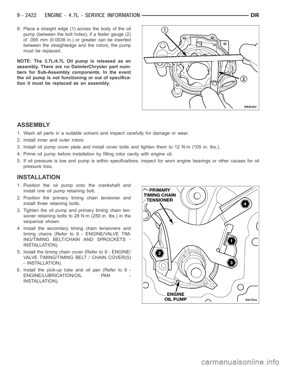
8. Place a straight edge (1) across the body of the oil
pump (between the bolt holes), if a feeler gauge (2)
of .095 mm (0.0038 in.) or greater can be inserted
between the straightedge and the rotors, the pump
must be replaced.
NOTE: The 3.7L/4.7L Oil pump is released as an
assembly. There are no DaimlerChrysler part num-
bers for Sub-Assembly components. In the event
the oil pump is not functioning or out of specifica-
tion it must be replaced as an assembly.
ASSEMBLY
1. Wash all parts in a suitable solvent and inspect carefully for damage or wear.
2. Install inner and outer rotors
3. Install oil pump cover plate and install cover bolts and tighten them to 12Nꞏm(105in.lbs.).
4. Prime oil pump before installation by filling rotor cavity with engine oil.
5. If oil pressure is low and pump is within specifications, inspect for worn engine bearings or other causes for oil
pressure loss.
INSTALLATION
1. Position the oil pump onto the crankshaft and
install one oil pump retaining bolt.
2. Position the primary timing chain tensioner and
install three retaining bolts.
3. Tighten the oil pump and primary timing chain ten-
sioner retaining bolts to 28 Nꞏm (250 in. lbs.) in the
sequence shown.
4. Install the secondary timing chain tensioners and
timing chains (Refer to 9 - ENGINE/VALVE TIM-
ING/TIMING BELT/CHAIN AND SPROCKETS -
INSTALLATION).
5. Install the timing chain cover (Refer to 9 - ENGINE/
VALVE TIMING/TIMING BELT / CHAIN COVER(S)
- INSTALLATION).
6. Install the pick-up tube and oil pan (Refer to 9 -
ENGINE/LUBRICATION/OIL PAN -
INSTALLATION).
Page 1732 of 5267
MANIFOLD - INTAKE
DESCRIPTION
The intake manifold is made of a composite material and features long runners which maximizes low end torque.
The intake manifold uses single plane sealing which consist of eight individual press in place port gaskets to prevent
leaks. Eight studs and two bolts are used to fasten the intake to the head.
DIAGNOSIS AND TESTING - INTAKE MANIFOLD LEAKAGE
An intake manifold air leak is characterized by lower than normal manifoldvacuum. Also, one or more cylinders may
not be functioning.
WARNING: USE EXTREME CAUTION WHEN THE ENGINE IS OPERATING. DO NOT STAND IN ADIRECT LINE
WITH THE FAN. DO NOT PUT YOUR HANDS NEAR THE PULLEYS, BELTS OR THE FAN. DO NOT WEAR
LOOSE CLOTHING.
1. Start the engine.
2. Spray a small stream of water at the suspected leak area.
3. If a change in RPM is observed the area of the suspected leak has been found.
4. Repair as required.
REMOVAL
1. Disconnect negative cable from battery.
2. Remove resonator assembly and air inlet hose.
3. Disconnect throttle and speed control cables.
4. Disconnect electrical connectors for the following components:
Manifold Absolute Pressure (MAP) Sensor
Intake Air Temperature (IAT) Sensor
Throttle Position (TPS) Sensor
Coolant Temperature (CTS) Sensor
Idle Air Control (IAC) Motor
5. Disconnect brake booster hose and positive crankcase ventilation (PCV)hose.
6. Disconnect generator electrical connections.
7. Disconnect air conditioning compressor electrical connections.
8. Disconnect left and right radio suppressor straps.
9. Disconnect and remove ignition coil towers (Refer to 8 - ELECTRICAL/IGNITION CONTROL/IGNITION COIL -
REMOVAL).
10. Remove top oil dipstick tube retaining bolt and ground strap.
11. Bleed fuel system (Refer to 14 - FUEL SYSTEM/FUEL DELIVERY - STANDARD PROCEDURE).
12. Remove fuel rail (Refer to 14 - FUEL SYSTEM/FUEL DELIVERY/FUEL RAIL - REMOVAL).
13. Remove throttle body assembly and mounting bracket.
14. Drain cooling system below coolant temperature level (Refer to 7 - COOLING - STANDARD PROCEDURE).
Page 1734 of 5267
INSTALLATION
1. Install intake manifold gaskets.
2. Position intake manifold.
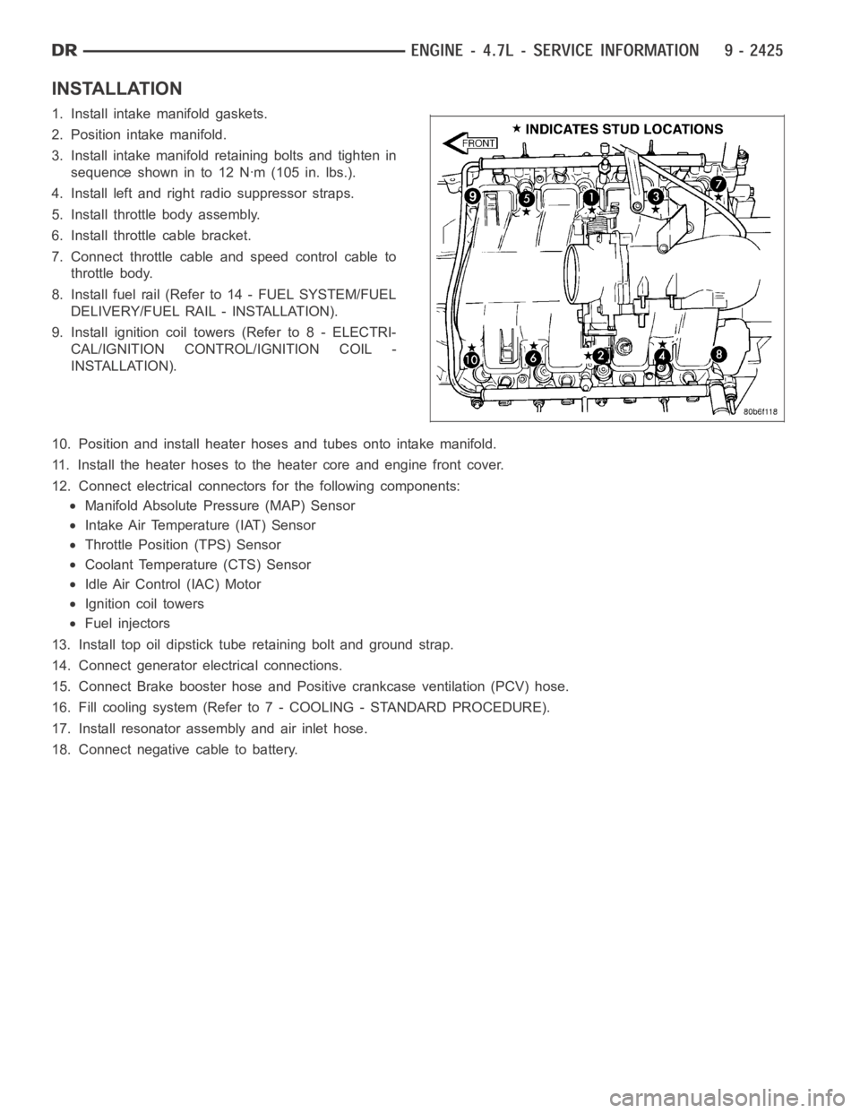
3. Install intake manifold retaining bolts and tighten in
sequence shown in to 12 Nꞏm (105 in. lbs.).
4. Install left and right radio suppressor straps.
5. Install throttle body assembly.
6. Install throttle cable bracket.
7. Connect throttle cable and speed control cable to
throttle body.
8. Install fuel rail (Refer to 14 - FUEL SYSTEM/FUEL
DELIVERY/FUEL RAIL - INSTALLATION).
9. Install ignition coil towers (Refer to 8 - ELECTRI-
CAL/IGNITION CONTROL/IGNITION COIL -
INSTALLATION).
10. Position and install heater hoses and tubes onto intake manifold.
11. Install the heater hoses to the heater core and engine front cover.
12. Connect electrical connectors for the following components:
Manifold Absolute Pressure (MAP) Sensor
Intake Air Temperature (IAT) Sensor
Throttle Position (TPS) Sensor
Coolant Temperature (CTS) Sensor
Idle Air Control (IAC) Motor
Ignition coil towers
Fuel injectors
13. Install top oil dipstick tube retaining bolt and ground strap.
14. Connect generator electrical connections.
15. Connect Brake booster hose and Positive crankcase ventilation (PCV) hose.
16. Fill cooling system (Refer to 7 - COOLING - STANDARD PROCEDURE).
17. Install resonator assembly and air inlet hose.
18. Connect negative cable to battery.
Page 1739 of 5267
VALVE TIMING
DESCRIPTION - TIMING DRIVE SYSTEM
The timing drive system has been designed to provide quiet performance andreliability to support anon-free
wheelingengine. Specifically the intake valves are non-free wheeling and can be easily damaged with forceful
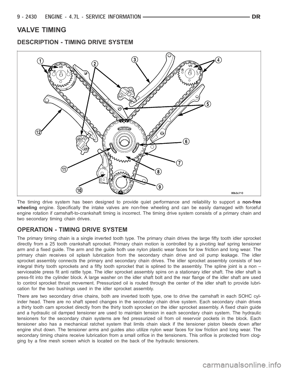
engine rotation if camshaft-to-crankshaft timing is incorrect. The timing drive system consists of a primary chain and
two secondary timing chain drives.
OPERATION - TIMING DRIVE SYSTEM
The primary timing chain is a single inverted tooth type. The primary chaindrives the large fifty tooth idler sprocket
directly from a 25 tooth crankshaft sprocket. Primary chain motion is controlled by a pivoting leaf spring tensioner
arm and a fixed guide. The arm and the guide both use nylon plastic wear facesfor low friction and long wear. The
primary chain receives oil splash lubrication from the secondary chain drive and oil pump leakage. The idler
sprocket assembly connects the primary and secondary chain drives. The idler sprocket assembly consists of two
integral thirty tooth sprockets and afifty tooth sprocket that is splinedto the assembly. The spline joint is a non –
serviceable press fit anti rattle type. The idler sprocket assembly spinson a stationary idler shaft. The idler shaft is
press-fit into the cylinder block. A large washer on the idler shaft bolt and the rear flange of the idler shaft are used
to control sprocket thrust movement. Pressurized oil is routed through the center of the idler shaft to provide lubri-
cation for the two bushings used in the idler sprocket assembly.
There are two secondary drive chains, both are inverted tooth type, one to drive the camshaft in each SOHC cyl-
inder head. There are no shaft speed changes in the secondary chain drive system. Each secondary chain drives
a thirty tooth cam sprocket directly from the thirty tooth sprocket on the idler sprocket assembly. A fixed chain guide
and a hydraulic oil damped tensioner are used to maintain tension in each secondary chain system. The hydraulic
tensioners for the secondary chainsystems are fed pressurized oil from oil reservoir pockets in the block. Each
tensioner also has a mechanical ratchet system that limits chain slack if the tensioner piston bleeds down after
engine shut down. The tensioner arms and guides also utilize nylon wear faces for low friction and long wear. The
secondary timing chains receive lubrication from a small orifice in the tensioners. This orifice is protected from clog-
ging by a fine mesh screen which is located on the back of the hydraulic tensioners.
Page 1743 of 5267
CAUTION: Remove excess oil from camshaft
sprocket retaining bolt before reinstalling bolt.
Failure to do so may cause over-torqueing of bolt
resulting in bolt failure.
6. Position the camshaft drive gear onto the camshaft,
remove oil from bolt then install the retaining bolt.
Using Special Tools, Spanner Wrench 6958 with
Adapter Pins 8346 and a suitable torque wrench
(1), Tighten retaining bolt to 122 Nꞏm (90 ft. Lbs.).
7. Remove special tool 8350 (3,4).
Page 1746 of 5267
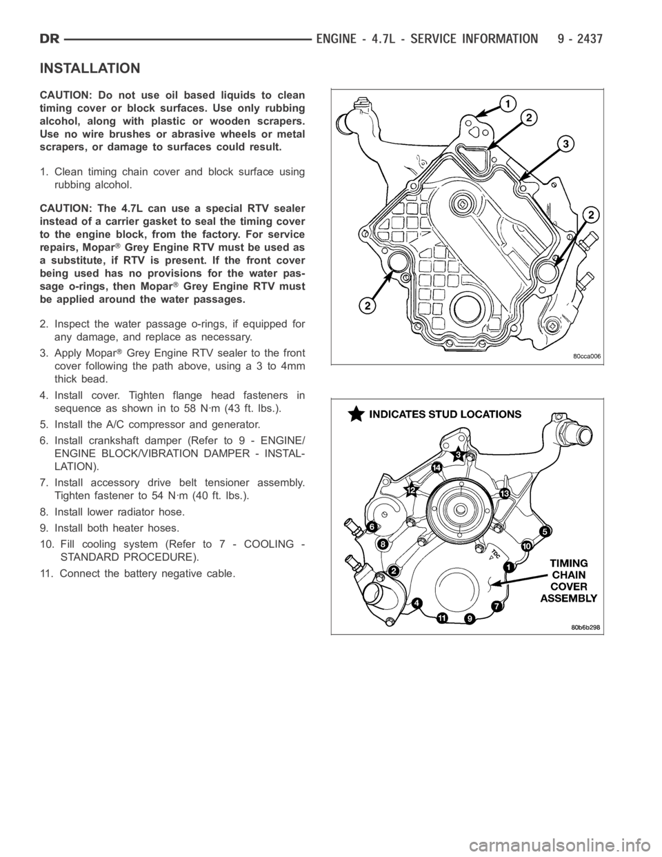
INSTALLATION
CAUTION: Do not use oil based liquids to clean
timing cover or block surfaces. Use only rubbing
alcohol, along with plastic or wooden scrapers.
Use no wire brushes or abrasive wheels or metal
scrapers, or damage to surfaces could result.
1. Clean timing chain cover and block surface using
rubbing alcohol.
CAUTION: The 4.7L can use a special RTV sealer
instead of a carrier gasket to seal the timing cover
to the engine block, from the factory. For service
repairs, Mopar
Grey Engine RTV must be used as
a substitute, if RTV is present. If the front cover
being used has no provisions for the water pas-
sage o-rings, then Mopar
Grey Engine RTV must
be applied around the water passages.
2. Inspect the water passage o-rings, if equipped for
any damage, and replace as necessary.
3. Apply Mopar
Grey Engine RTV sealer to the front
cover following the path above, using a 3 to 4mm
thick bead.
4. Install cover. Tighten flange head fasteners in
sequence as shown in to 58 Nꞏm (43 ft. lbs.).
5. Install the A/C compressor and generator.
6. Install crankshaft damper (Refer to 9 - ENGINE/
ENGINE BLOCK/VIBRATION DAMPER - INSTAL-
LATION).
7. Install accessory drive belt tensioner assembly.
Tighten fastener to 54 Nꞏm (40 ft. lbs.).
8. Install lower radiator hose.
9. Install both heater hoses.
10. Fill cooling system (Refer to 7 - COOLING -
STANDARD PROCEDURE).
11. Connect the battery negative cable.
Page 1748 of 5267
6. Remove power steering pump (Refer to 19 -
STEERING/PUMP - REMOVAL).
7. Remove access plugs (1,2) from left and right cyl-
inder heads for access to chain guide fasteners.
8. Remove the oil fill housing to gain access to the
right side tensioner arm fastener.
9. Remove crankshaft damper (Refer to 9 - ENGINE/
ENGINE BLOCK/VIBRATION DAMPER -
REMOVAL) and timing chain cover (Refer to 9 -
ENGINE/VALVE TIMING/TIMING BELT / CHAIN
COVER(S) - REMOVAL).
10. Collapse and pin primary chain tensioner (1).
CAUTION: Plate behind left secondary chain ten-
sioner could fall into oil pan. Therefore, cover pan
opening.
11. Remove secondary chain tensioners.
12. Remove camshaft position sensor (1) from right
cylinder head.