Page 1709 of 5267
RINGS - PISTON
STANDARD PROCEDURE - PISTON RING FITTING
Before reinstalling used rings or installing new rings,
the ring clearances must be checked.
1. Wipe the cylinder bore clean.
2. Insert the ring in the cylinder bore.
NOTE: The ring gap measurement must be made
with the ring positioned at least 12mm (0.50 inch.)
from bottom of cylinder bore.
3. Using a piston, to ensure that the ring is squared in
the cylinder bore, slide the ring downward into the
cylinder.
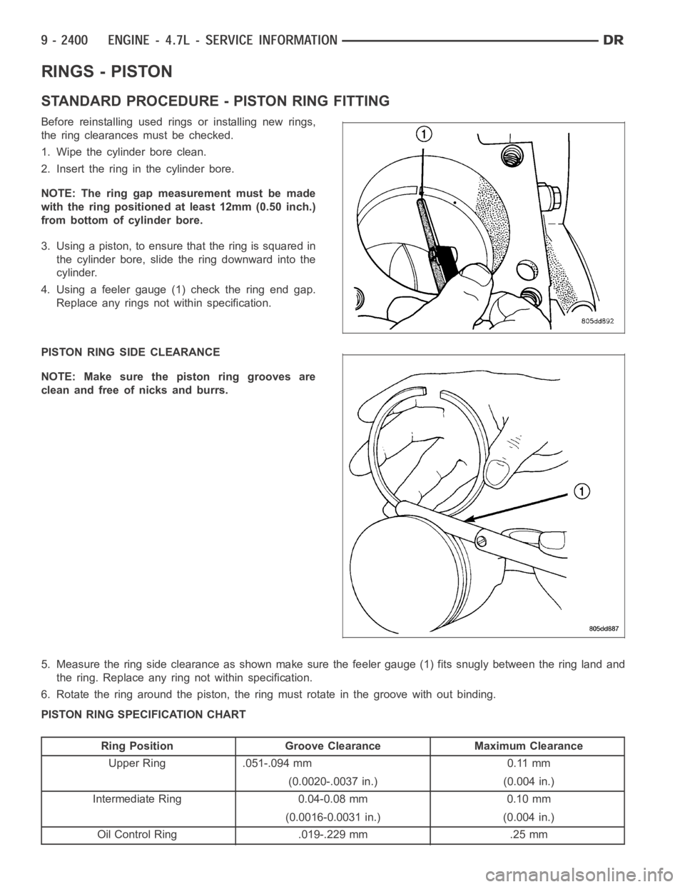
4. Using a feeler gauge (1) check the ring end gap.
Replace any rings not within specification.
PISTON RING SIDE CLEARANCE
NOTE: Make sure the piston ring grooves are
clean and free of nicks and burrs.
5. Measure the ring side clearance as shown make sure the feeler gauge (1) fits snugly between the ring land and
the ring. Replace any ring not within specification.
6. Rotate the ring around the piston, the ring must rotate in the groove without binding.
PISTON RING SPECIFICATION CHART
Ring Position Groove Clearance Maximum Clearance
Upper Ring .051-.094 mm 0.11 mm
(0.0020-.0037 in.) (0.004 in.)
Intermediate Ring 0.04-0.08 mm 0.10 mm
(0.0016-0.0031 in.) (0.004 in.)
Oil Control Ring .019-.229 mm .25 mm
Page 1710 of 5267
Ring Position Groove Clearance Maximum Clearance
(Steel Rails) (.0007-.0090 in.) (0.010 in.)
Ring Position Ring Gap Wear Limit
Upper Ring 0.20-0.36 mm 0.43 mm
(0.0079-0.0142 in.) (0.0017 in.)
Intermediate Ring 0.37-0.63 mm 0.74 mm
(0.0146-0.0249 in.) (0.029 in.)
Oil Control Ring 0.025-0.76 mm 1.55 mm
(Steel Rail) (0.0099- 0.03 in.) (0.061 in.)
7. The No. 1 and No. 2 piston rings have a different
cross section. Ensure No. 2 ring is installed with
manufacturers I.D. mark (Dot) facing up, towards
top of the piston.
NOTE: Piston rings are installed in the following
order:
Oil ring expander.
Upper oil ring side rail.
Lower oil ring side rail.
No. 2 Intermediate piston ring.
No. 1 Upper piston ring.
8. Install the oil ring expander.
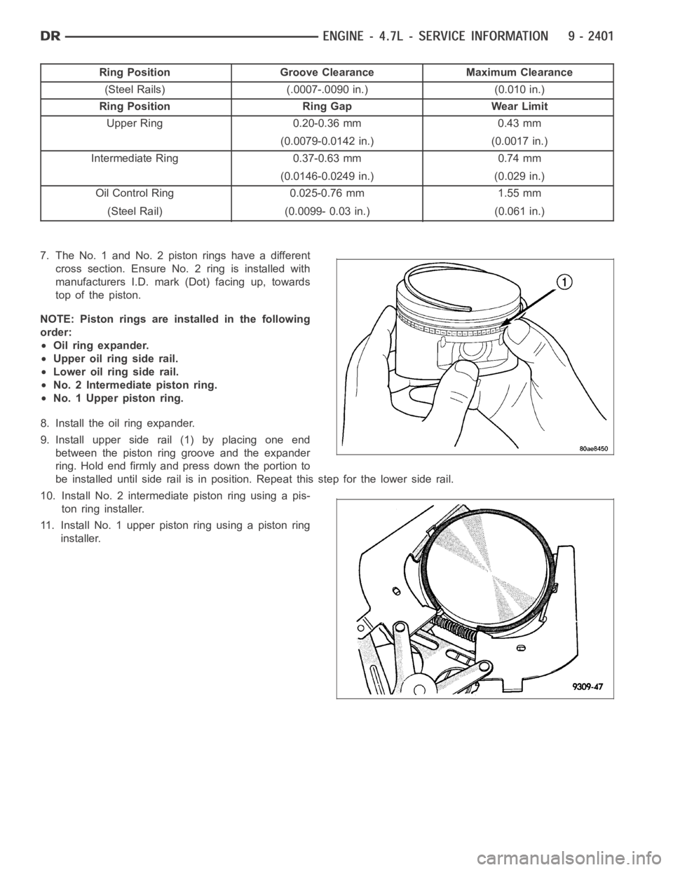
9. Install upper side rail (1) by placing one end
between the piston ring groove and the expander
ring. Hold end firmly and press down the portion to
be installed until side rail is in position. Repeat this step for the lower side rail.
10. Install No. 2 intermediate piston ring using a pis-
ton ring installer.
11. Install No. 1 upper piston ring using a piston ring
installer.
Page 1715 of 5267
MOUNT - FRONT
REMOVAL
2WD
1. Disconnect the negative cable from the battery.
CAUTION: Remove the viscous fan before raising engine. Failure to do so maycause damage to the fan
blade, fan clutch and fan shroud.
2. Remove the viscous fan (Refer to 7 - COOLING/ENGINE/FAN DRIVE VISCOUS CLUTCH - REMOVAL).
3. Raise the vehicle.
4. Remove the engine oil filter.
5. Remove the oil drain trough.
6. Support the engine with a suitable jack and a block of wood across the fullwidth of the engine oil pan.
7. Support the front axle with a suitable jack.
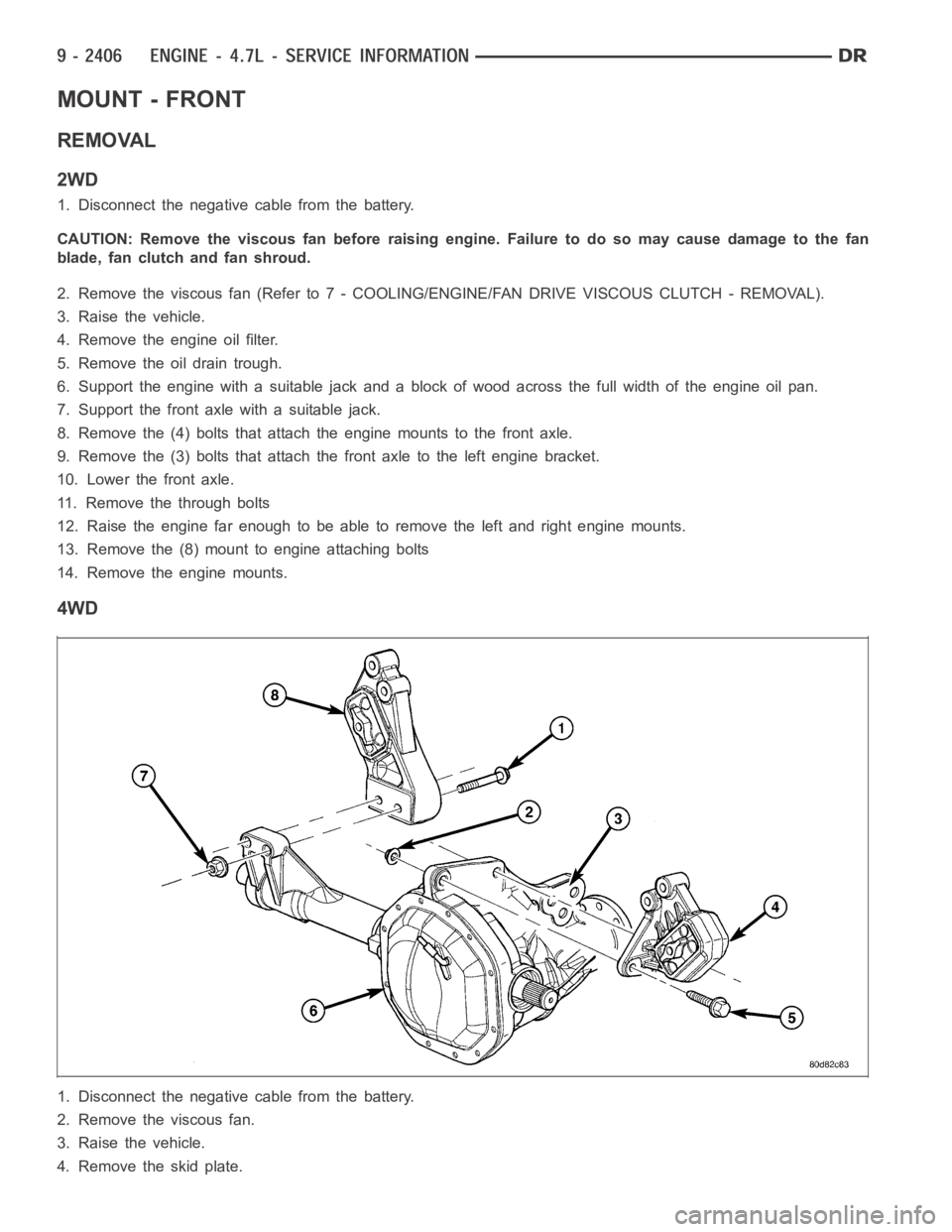
8. Remove the (4) bolts that attach the engine mounts to the front axle.
9. Remove the (3) bolts that attach the front axle to the left engine bracket.
10. Lower the front axle.
11. Remove the through bolts
12. Raise the engine far enough to be able to remove the left and right enginemounts.
13. Remove the (8) mount to engine attaching bolts
14. Remove the engine mounts.
4WD
1. Disconnect the negative cable from the battery.
2. Remove the viscous fan.
3. Raise the vehicle.
4. Removetheskidplate.
Page 1716 of 5267
5. Remove the front crossmember.
6. Remove the engine oil filter.
7. Remove the oil drain trough.
8. Support the engine with a suitable jack and a block of wood across the fullwidth of the engine oil pan.
9. Support the front axle with a suitable jack.
10. Remove the 4 bolts that attach the engine mounts to the front axle (6).
11. Remove the 3 bolts (3) that attach the front axle to the left engine bracket.
12. Lower the front axle.
13. Remove the through bolts
14. Raise the engine far enough to be able to remove the left and right enginemounts.
15. Remove the engine mounts (4,8).
Page 1717 of 5267
16. Remove the engine mount brackets (2).
INSTALLATION
2WD
NOTE: For mount to engine block and left engine bracket to front axle bolts,apply MoparLock and Seal
Adhesive, Medium Strength Threadlocker.
1. Install the right and left side engine mounts to the engine block with (8)bolts. Torque bolts to 54 Nꞏm (40 ft. lbs.).
2. Insert the (2) through bolts into the right and left side engine mounts and loose assemble the two nuts onto the
through bolts.
3. Lower the engine until the through bolts rest onto the slots in the frame brackets.
4. Tighten the through bolt nuts to 94 Nꞏm (70 ft. lbs.).
5. Install the oil drain trough.
6. Install the engine oil filter.
7. Lower the vehicle.
8. Install the viscous fan (Refer to 7 - COOLING/ENGINE/FAN DRIVE VISCOUS CLUTCH - REMOVAL).
9. Reconnect the negative battery cable.
Page 1718 of 5267
4WD
NOTE: For mount to engine block and left engine bracket to front axle bolts,apply MoparLock and Seal
Adhesive, Medium Strength Threadlocker.
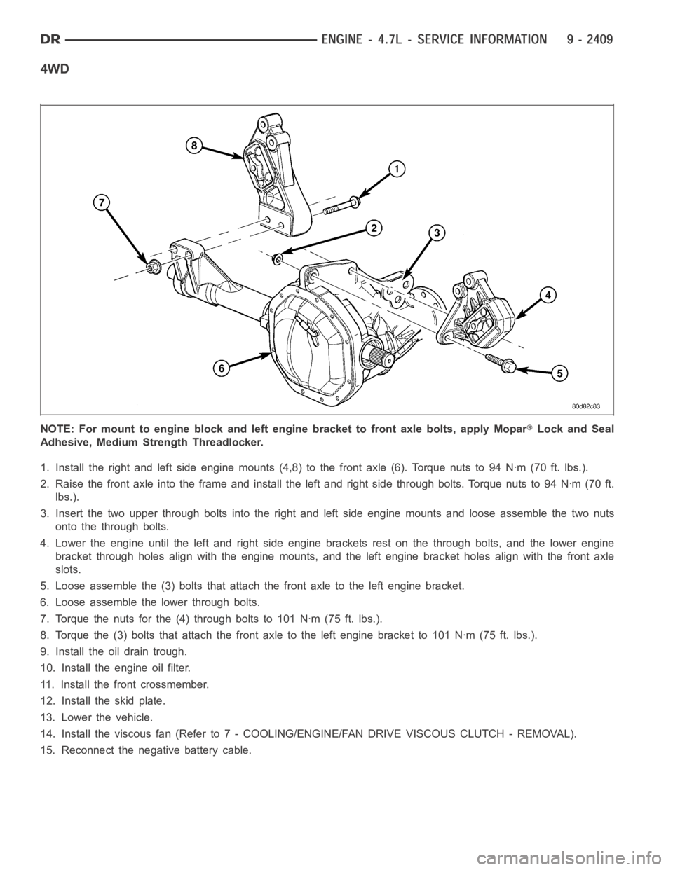
1. Install the right and left side engine mounts (4,8) to the front axle (6).Torquenutsto94Nꞏm(70ft.lbs.).
2. Raise the front axle into the frame and install the left and right side through bolts. Torque nuts to 94 Nꞏm (70 ft.
lbs.).
3. Insert the two upper through bolts into the right and left side engine mounts and loose assemble the two nuts
onto the through bolts.
4. Lower the engine until the left and right side engine brackets rest on thethrough bolts, and the lower engine
bracket through holes align with the engine mounts, and the left engine bracket holes align with the front axle
slots.
5. Loose assemble the (3) bolts that attach the front axle to the left enginebracket.
6. Loose assemble the lower through bolts.
7. Torque the nuts for the (4) through bolts to 101 Nꞏm (75 ft. lbs.).
8. Torque the (3) bolts that attach the front axle to the left engine bracketto 101 Nꞏm (75 ft. lbs.).
9. Install the oil drain trough.
10. Install the engine oil filter.
11. Install the front crossmember.
12. Install the skid plate.
13. Lower the vehicle.
14. Install the viscous fan (Refer to 7 - COOLING/ENGINE/FAN DRIVE VISCOUSCLUTCH - REMOVAL).
15. Reconnect the negative battery cable.
Page 1720 of 5267
LUBRICATION
DESCRIPTION
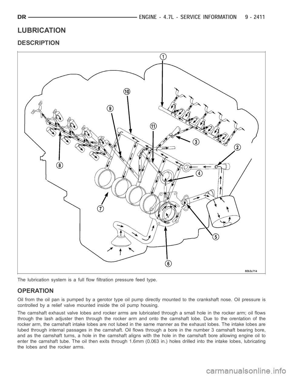
The lubrication system is a full flow filtration pressure feed type.
OPERATION
Oil from the oil pan is pumped by a gerotor type oil pump directly mounted to the crankshaft nose. Oil pressure is
controlled by a relief valve mounted inside the oil pump housing.
The camshaft exhaust valve lobes and rocker arms are lubricated through a small hole in the rocker arm; oil flows
through the lash adjuster then through the rocker arm and onto the camshaftlobe. Due to the orentation of the
rocker arm, the camshaft intake lobes are not lubed in the same manner as theexhaust lobes. The intake lobes are
lubed through internal passages in the camshaft. Oil flows through a bore in the number 3 camshaft bearing bore,
and as the camshaft turns, a hole in the camshaft aligns with the hole in the camshaft bore allowing engine oil to
enter the camshaft tube. The oil then exits through 1.6mm (0.063 in.) holesdrilled into the intake lobes, lubricating
the lobes and the rocker arms.
Page 1721 of 5267
Engine Lubrication Flow Chart—Block: Table 1
FROM TO
Oil Pickup Tube Oil Pump
Oil Pump Oil Filter
Oil Filter Block Main Oil Gallery
Block Main Oil Gallery 1. Crankshaft Main Journal
2. Left Cylinder Head*
3. Right Cylinder Head*
Crankshaft Main Journals Crankshaft Rod Journals
Crankshaft Number One Main Journal 1.Front Timing Chain Idler Shaft
2.Both Secondary Chain Tensioners
Left Cylinder Head See Table 2
Right Cylinder Head See Table 2
* The cylinder head gaskets have an oil restricter to control oil flow to thecylinder heads.
Engine Lubrication Flow Chart—Cylinder Heads: Table 2
FROM TO
Cylinder Head Oil Port (in bolt hole) Diagonal Cross Drilling to Main Oil Gallery
Main Oil Gallery (drilled through headfrom rear to front) 1. Base of Camshaft Towers
2. Lash Adjuster Towers
Base of Camshaft Towers Vertical Drilling Through Tower to Camshaft Bearings**
Lash Adjuster Towers Diagonal Drillings to Hydraulic Lash Adjuster Pockets
** The number three camshaft bearing journal feeds oil into the hollow camshaft tubes. Oil is routed to the intake
lobes, which have oil passages drilled into them to lubricate the rocker arms.
DIAGNOSIS AND TESTING
DIAGNOSIS AND TESTING - CHECKING ENGINE OIL PRESSURE
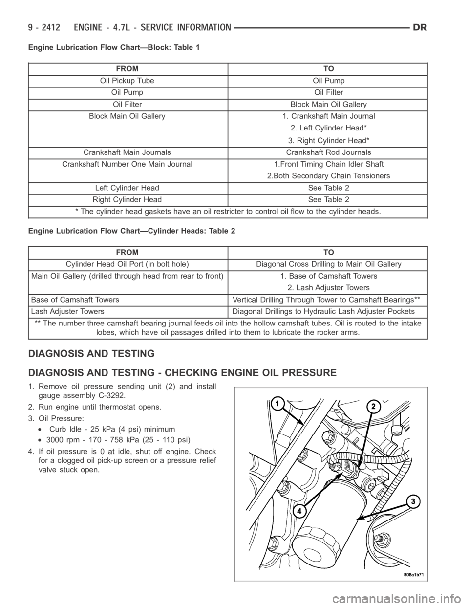
1. Remove oil pressure sending unit (2) and install
gauge assembly C-3292.
2. Run engine until thermostat opens.
3. Oil Pressure:
Curb Idle - 25 kPa (4 psi) minimum
3000 rpm - 170 - 758 kPa (25 - 110 psi)
4. If oil pressure is 0 at idle, shut off engine. Check
for a clogged oil pick-up screen or a pressure relief
valve stuck open.