Page 1684 of 5267
INSTALLATION
CAUTION: Make sure the rocker arms are installed with the concave pocket over the lash adjusters. Failure
to do so may cause severe damage to the rocker arms and/or lash adjusters.
NOTE: Coat the rocker arms with clean engine oil prior to installation.
1. For rocker arm installation on cylinders 3 and 5 Rotate the crankshaft until cylinder #1 is at TDC exhaust stroke.
2. For rocker arm installation on cylinders 2 and 8 Rotate the crankshaft until cylinder #1 is at TDC compression
stroke.
3. For rocker arm installation on cylinders 4 and 6 Rotate the crankshaft until cylinder #3 is at TDC compression
stroke.
4. For rocker arm installation on cylinders 1 and 7 Rotate the crankshaft until cylinder #2 is at TDC compression
stroke.
5. Using special tool 8516 press downward on the valve spring, install rocker arm.
6. Install the cylinder head cover (Refer to 9 - ENGINE/CYLINDER HEAD/CYLINDER HEAD COVER(S) - INSTAL-
LATION).
Page 1686 of 5267
INSTALLATION
1. Coat the valve stem with clean engine oil and
install the valve stem seal. Make sure the seal is
fully seated and that the garter spring at the top of
the seal is intact.
2. Install the spring (6) and the spring retainer (2).
3. Using Special Tool 8387 Valve Spring Compressor,
compress the spring and install the two valve
spring retainer halves.
4. Release the valve spring compressor and make
sure the two spring retainer halves and the spring
retainer are fully seated.
5. Position the hydraulic lash adjusters and rocker
arms.
6. Install the cylinder head cover (Refer to 9 -
ENGINE/CYLINDER HEAD/CYLINDER HEAD
COVER(S) - INSTALLATION).
Page 1688 of 5267

ENGINE BLOCK
DESCRIPTION
The cylinder block is made of cast iron.The block is a closed deck design with the left bank forward. To provide
high rigidity and improved NVH an enhanced compacted graphite bedplate isbolted to the block. The block design
allows coolant flow between the cylinders bores, and an internal coolant bypass to a single poppet inlet thermostat
is included in the cast aluminum front cover.
STANDARD PROCEDURE - CYLINDER BORE HONING
Before honing, stuff plenty of clean shop towels under
the bores and over the crankshaft to keep abrasive
materials from entering the crankshaft area.
1. Used carefully, the Cylinder Bore Sizing Hone
C-823, equipped with 220 grit stones, is the best
tool for this job. In addition to deglazing, it will
reduce taper and out-of-round, as well as removing
light scuffing, scoring and scratches. Usually, a few
strokes will clean up a bore and maintain the
required limits.
CAUTION: DO NOT use rigid type hones to remove
cylinder wall glaze.
2. Deglazing of the cylinder walls may be done if the
cylinder bore is straight and round. Use a cylinder
surfacing hone, Honing Tool C-3501, equipped with
280 grit stones (C-3501-3810). about 20-60
strokes, depending on the bore condition, will be
sufficient to provide a satisfactory surface. Using
honing oil C-3501-3880, or a light honing oil, avail-
able from major oil distributors.
CAUTION: DO NOT use engine or transmission oil, mineral spirits, or kerosene.
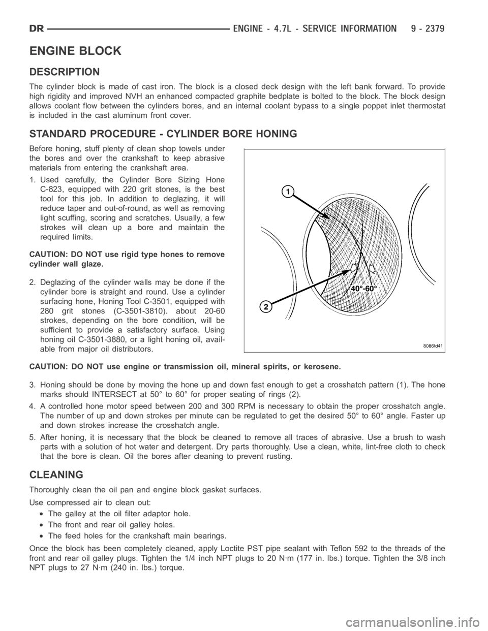
3. Honing should be done by moving the hone up and down fast enough to get a crosshatch pattern (1). The hone
marks should INTERSECT at 50° to 60° for proper seating of rings (2).
4. A controlled hone motor speed between 200 and 300 RPM is necessary to obtain the proper crosshatch angle.
The number of up and down strokes per minute can be regulated to get the desired 50° to 60° angle. Faster up
and down strokes increase the crosshatch angle.
5. After honing, it is necessary that the block be cleaned to remove all traces of abrasive. Use a brush to wash
parts with a solution of hot water and detergent. Dry parts thoroughly. Usea clean, white, lint-free cloth to check
that the bore is clean. Oil the bores after cleaning to prevent rusting.
CLEANING
Thoroughly clean the oil pan and engine block gasket surfaces.
Use compressed air to clean out:
The galley at the oil filter adaptor hole.
The front and rear oil galley holes.
The feed holes for the crankshaft main bearings.
Once the block has been completely cleaned, apply Loctite PST pipe sealantwith Teflon 592 to the threads of the
front and rear oil galley plugs. Tighten the 1/4 inch NPT plugs to 20 Nꞏm (177in. lbs.) torque. Tighten the 3/8 inch
NPT plugs to 27 Nꞏm (240 in. lbs.) torque.
Page 1690 of 5267
BEARINGS - CONNECTING ROD
STANDARD PROCEDURE - CONNECTING ROD BEARING FITTING
Inspect the connecting rod bearings for scoring. Check
the bearings for normal wear patterns, scoring, groov-
ing, fatigue and pitting. Replace any bearing that
shows abnormal wear.
Inspect the connecting rod journals for signs of scor-
ing, nicks and burrs.
Misaligned or bent connecting rods can cause abnor-
mal wear on pistons, piston rings, cylinder walls, con-
necting rod bearings and crankshaft connecting rod
journals. If wear patterns or damage to any of these
components indicate the probability of a misaligned connecting rod, inspect it for correct rod alignment. Replace
misaligned, bent or twisted connecting rods.
1. Wipe the oil from the connecting rod journal.
2. Lubricate the upper bearing insert (2) and install in
connecting rod (1).Center bearing insert (2) in
connecting rod.
Page 1691 of 5267
3. Use piston ring compressor (3) and Guide Pins
Special Tool 8507 (4) to install the rod and piston
assemblies. The oil slinger slots in the rods must
face front of the engine. The “F”’s near the piston
wrist pin bore should point to the front of the
engine.
4. Install the lower bearing insert in the bearing cap
Center bearing insert (2) in connecting rod (1)..
The lower insert must be dry. Place strip of Plasti-
gage across full width of the lower insert at the
center of bearing cap. Plastigage must not crumble
in use. If brittle, obtain fresh stock.
Page 1694 of 5267

CRANKSHAFT
DESCRIPTION
The crankshaft is constructed of nodular cast iron. The crankshaft is a crosshaped four throw design with eight
counterweights for balancing purposes. The crankshaft is supported by five select fit main bearings with the number
three serving as the thrust washer location. The main journals of the crankshaft are cross drilled to improve rod
bearing lubrication. The number eight counterweight has provisions for crankshaft position sensor target wheel
mounting. The select fit main bearing markings are located on the rear sideof the target wheel. The crankshaft oil
seals are one piece design. The front oil seal is retained in the timing chain cover, and the rear seal is pressed in
to a bore formed by the cylinder block and the bedplate assembly.
REMOVAL
NOTE: To remove the crankshaft from the engine, the engine must be removed from the vehicle.
1. Remove the engine. (Refer to 9 - ENGINE - REMOVAL).
2. Remove the engine oil pump. (Refer to 9 - ENGINE/LUBRICATION/OIL PUMP - REMOVAL).
CAUTION: DO NOT pry on the oil pan gasket when removing the oil pan, The oil pan gasket is mounted to
the cylinder block in three locations and will remain attached to block when removing oil pan. Gasket can
not be removed with oil pan.
3. Remove oil pan. (Refer to 9 - ENGINE/LUBRICATION/OIL PAN - REMOVAL).
4. Remove the oil pump pickup tube and oil pan gasket /windage tray.
5. Remove the bedplate mounting bolts. Note the location of the three stud bolts for installation.
6. Remove the connecting rods from the crankshaft.
CAUTION: The bedplate to cylinder block mating
surface is a critical sealing surface. Do not pry on
or damage this surface in anyway.
NOTE: The bedplate contains the lower main bear-
ing halves. Use care when handling bedplate as
not to drop or damage bearing halves. Installing
main bearing halves in the wrong position will
cause sever damage to the crankshaft.
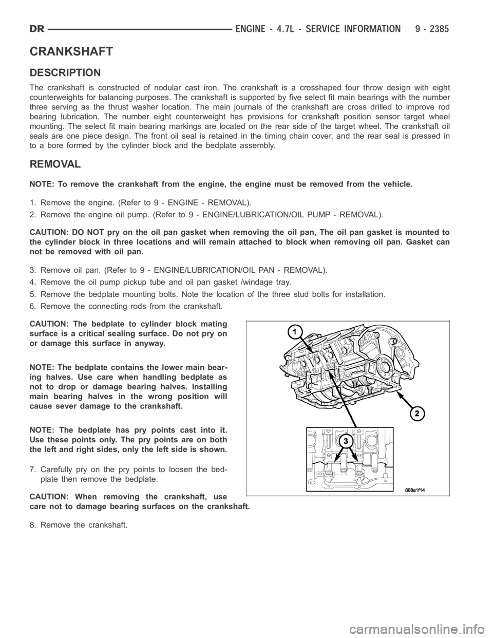
NOTE: The bedplate has pry points cast into it.
Use these points only. The pry points are on both
the left and right sides, only the left side is shown.
7. Carefully pry on the pry points to loosen the bed-
plate then remove the bedplate.
CAUTION: When removing the crankshaft, use
care not to damage bearing surfaces on the crankshaft.
8. Remove the crankshaft.
Page 1695 of 5267

INSPECTION
NOTE: Thoroughly inspect the connecting rod bearing bores and main bearing bores for scoring, blueing or
severe scratches. Further disassembly may be required.
If connecting rod bearing bores show damage, the cylinder heads must be removed to service the piston and rod
assemblies. If the bedplate or the cylinder block main bearing bores show damage the engine must be replaced.
1. If required, remove the main bearing halves from the cylinder block and bedplate.
2. Thoroughly clean the bedplate to cylinder block sealing surfaces and main bearing bores. Remove all oil and
sealant residue.
3. Inspect the bedplate main bearing bores for cracks, scoring or severe blueing. If either condition exists the
engine must be replaced.
4. Inspect the crankshaft thrust washers for scoring, scratches, wear or blueing. If either condition exist replace the
thrust washer.
5. Inspect the oil pan gasket/windage tray for splits, tears or cracks in the gasket sealing surfaces. Replace gasket
as necessary.
INSTALLATION
CAUTION: Main bearings are select fit. (Refer to 9
- ENGINE/ENGINE BLOCK/CRANKSHAFT MAIN
BEARINGS - STANDARD PROCEDURE) for proper
bearing selections.
1. Lubricate upper main bearing halves with clean
engine oil.
CAUTION: When installing crankshaft, use care
not to damage bearing surfaces on the crankshaft.
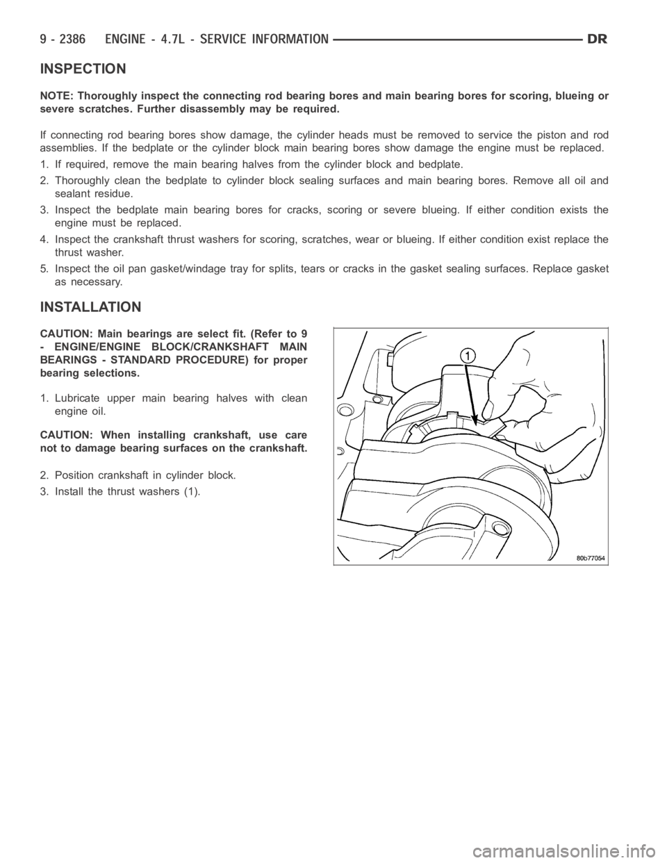
2. Position crankshaft in cylinder block.
3. Install the thrust washers (1).
Page 1696 of 5267
CAUTION: The bedplate to cylinder block mateing
surface must be coated with sealant prior to
installation. Failure to do so will cause severe oil
leaks.
NOTE: The installation time to install the bedplate
after the sealant has been applied is critical.
NOTE: Make sure that the bedplate and cylinder
block sealing surfaces are clean and free of oil or
other contaminants. Contaminants on the sealing
surfaces may cause main bearing distortion and/or
oil leaks.
4. Apply a 2.5mm (0.100 inch) bead of Mopar
Gen II
Silicone Rubber Adhesive sealant (2) to the cylin-
der block-to-bedplate mating surface (1) as shown.
5. Coat the crankshaft main bearing journals with
clean engine oil and position the bedplate onto the
cylinder block.