2006 DODGE RAM SRT-10 transmission fluid
[x] Cancel search: transmission fluidPage 3993 of 5267
Manual lever detent ball.
Throttle lever.
Fluid filter.
Pressure adjusting screw bracket.
Governor pressure solenoid.
Governor pressure sensor (includes transmission temperature thermistor).
Converter clutch/overdrive solenoid assembly and harness.
Governor housing gasket.
Solenoid case connector O-rings.
1. Shift transmission into NEUTRAL.
2. Raise vehicle.
3. Remove gearshift and throttle levers from shaft of
valve body manual lever.
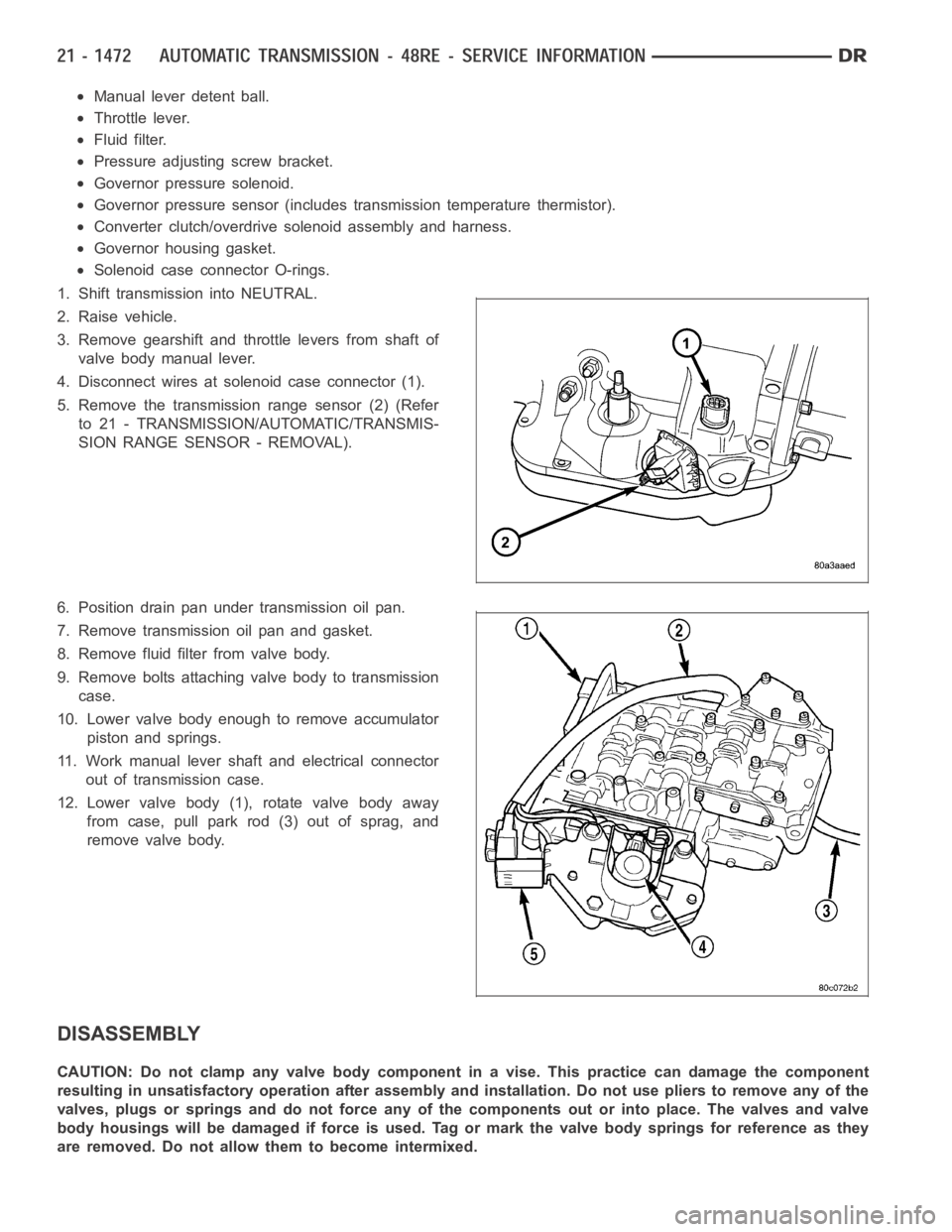
4. Disconnect wires at solenoid case connector (1).
5. Remove the transmission range sensor (2) (Refer
to 21 - TRANSMISSION/AUTOMATIC/TRANSMIS-
SION RANGE SENSOR - REMOVAL).
6. Position drain pan under transmission oil pan.
7. Remove transmission oil pan and gasket.
8. Remove fluid filter from valve body.
9. Remove bolts attaching valve body to transmission
case.
10. Lower valve body enough to remove accumulator
piston and springs.
11. Work manual lever shaft and electrical connector
out of transmission case.
12. Lower valve body (1), rotate valve body away
from case, pull park rod (3) out of sprag, and
remove valve body.
DISASSEMBLY
CAUTION: Do not clamp any valve body component in a vise. This practice can damage the component
resulting in unsatisfactory operation after assembly and installation.Do not use pliers to remove any of the
valves, plugs or springs and do not force any of the components out or into place. The valves and valve
body housings will be damaged if force is used. Tag or mark the valve body springs for reference as they
are removed. Do not allow them to become intermixed.
Page 4008 of 5267
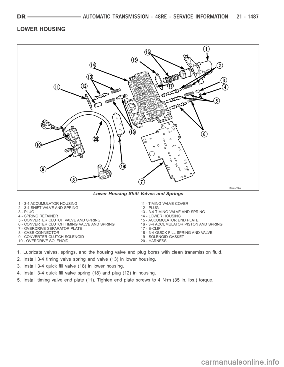
LOWER HOUSING
1. Lubricate valves, springs, and the housing valve and plug bores with clean transmission fluid.
2. Install 3-4 timing valve spring and valve (13) in lower housing.
3. Install 3-4 quick fill valve (18) in lower housing.
4. Install 3-4 quick fill valve spring (18) and plug (12) in housing.
5. Install timing valve end plate (11). Tighten end plate screws to 4 Nꞏm (35in. lbs.) torque.
Lower Housing Shift Valves and Springs
1 - 3-4 ACCUMULATOR HOUSING 11 - TIMING VALVE COVER
2 - 3-4 SHIFT VALVE AND SPRING 12 - PLUG
3 - PLUG 13 - 3-4 TIMING VALVE AND SPRING
4 - SPRING RETAINER 14 - LOWER HOUSING
5 - CONVERTER CLUTCH VALVE AND SPRING 15 - ACCUMULATOR END PLATE
6 - CONVERTER CLUTCH TIMING VALVE AND SPRING 16 - 3-4 ACCUMULATOR PISTON ANDSPRING
7 - OVERDRIVE SEPARATOR PLATE 17 - E-CLIP
8 - CASE CONNECTOR 18 - 3-4 QUICK FILL SPRING AND VALVE
9 - CONVERTER CLUTCH SOLENOID 19 - SOLENOID GASKET
10 - OVERDRIVE SOLENOID 20 - HARNESS
Page 4009 of 5267
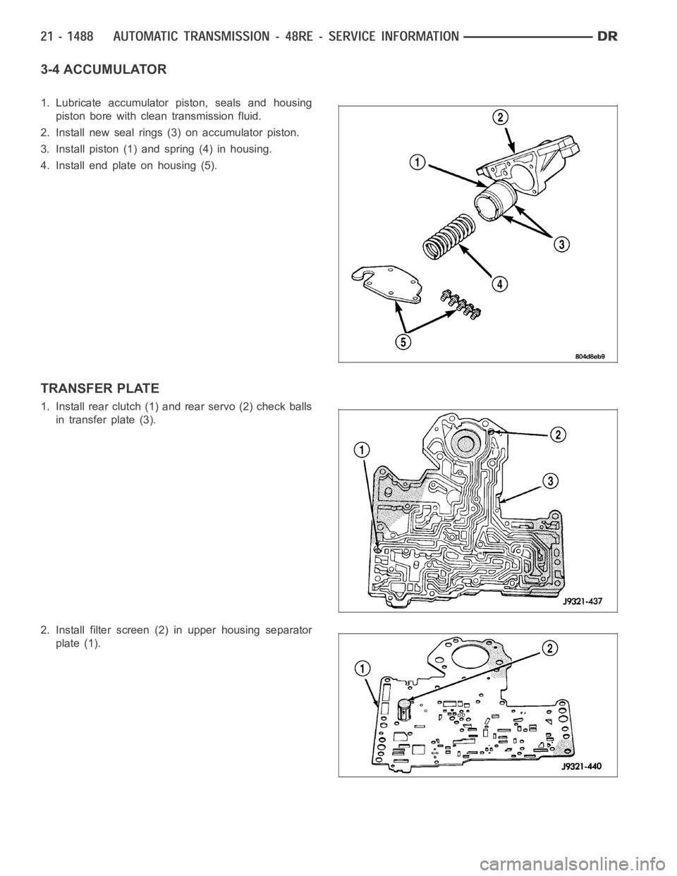
3-4 ACCUMULATOR
1. Lubricate accumulator piston, seals and housing
piston bore with clean transmission fluid.
2. Install new seal rings (3) on accumulator piston.
3. Install piston (1) and spring (4) in housing.
4. Install end plate on housing (5).
TRANSFER PLATE
1. Install rear clutch (1) and rear servo (2) check balls
in transfer plate (3).
2. Install filter screen (2) in upper housing separator
plate (1).
Page 4012 of 5267
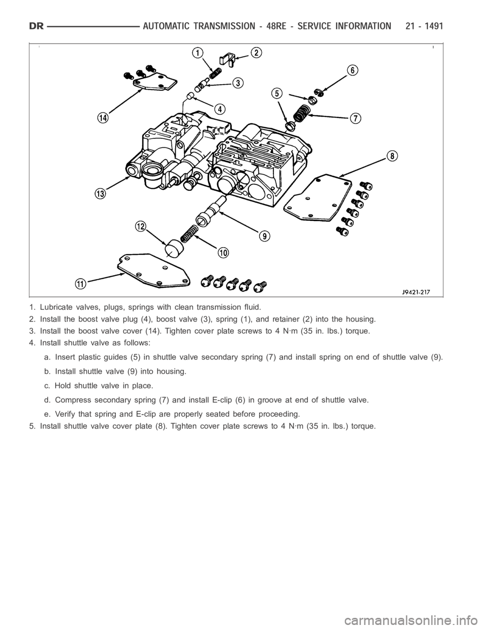
1. Lubricate valves, plugs, springs with clean transmission fluid.
2. Install the boost valve plug (4), boost valve (3), spring (1), and retainer (2) into the housing.
3. Install the boost valve cover (14). Tighten cover plate screws to 4 Nꞏm (35 in. lbs.) torque.
4. Install shuttle valve as follows:
a. Insert plastic guides (5) in shuttle valve secondary spring (7) and install spring on end of shuttle valve (9).
b. Install shuttle valve (9) into housing.
c. Hold shuttle valve in place.
d. Compress secondary spring (7) and install E-clip (6) in groove at end of shuttle valve.
e. Verify that spring and E-clip are properly seated before proceeding.
5. Install shuttle valve cover plate (8). Tighten cover plate screws to 4 Nꞏm (35 in. lbs.) torque.
Page 4017 of 5267
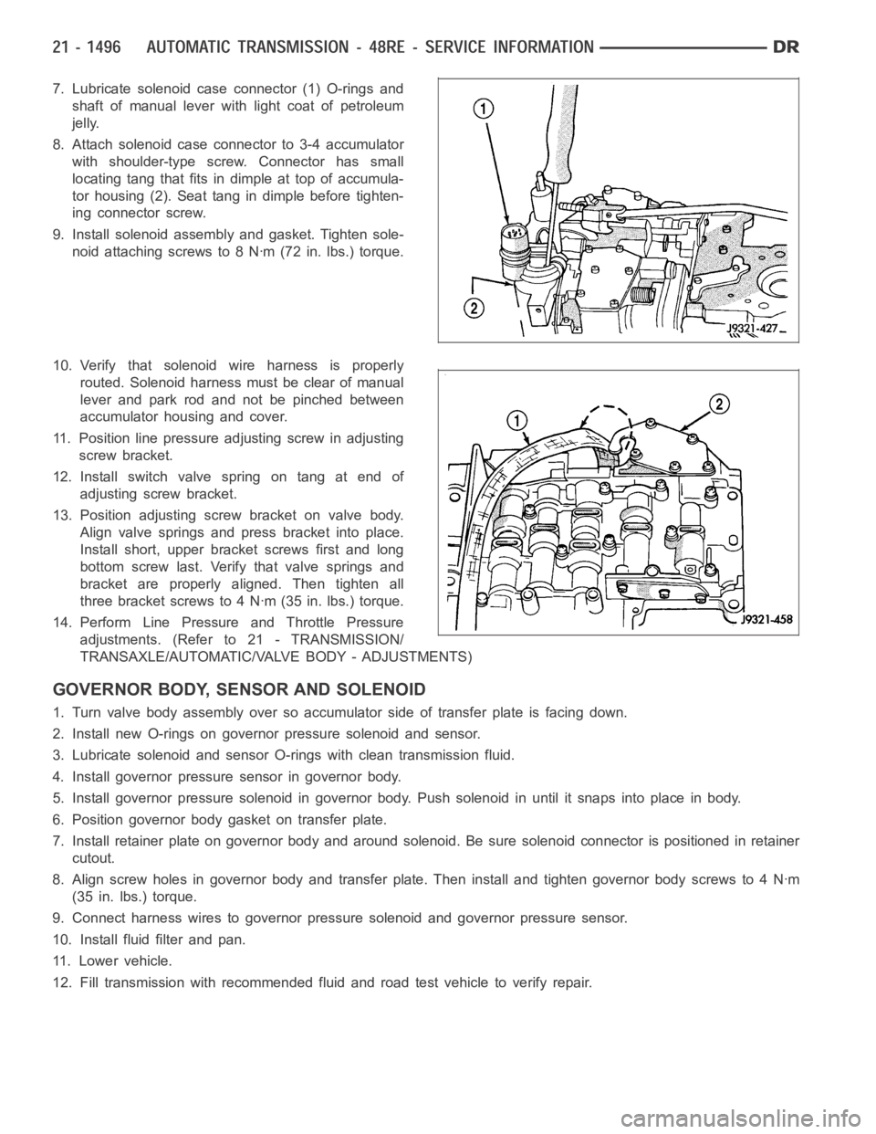
7. Lubricate solenoid case connector (1) O-rings and
shaft of manual lever with light coat of petroleum
jelly.
8. Attach solenoid case connector to 3-4 accumulator
with shoulder-type screw. Connector has small
locating tang that fits indimple at top of accumula-
tor housing (2). Seat tang in dimple before tighten-
ing connector screw.
9. Install solenoid assembly and gasket. Tighten sole-
noid attaching screws to 8 Nꞏm (72 in. lbs.) torque.
10. Verify that solenoid wire harness is properly
routed. Solenoid harness must be clear of manual
lever and park rod and not be pinched between
accumulator housing and cover.
11. Position line pressure adjusting screw in adjusting
screw bracket.
12. Install switch valve spring on tang at end of
adjusting screw bracket.
13. Position adjusting screw bracket on valve body.
Align valve springs and press bracket into place.
Install short, upper bracket screws first and long
bottom screw last. Verify that valve springs and
bracket are properly aligned. Then tighten all
three bracket screws to 4 Nꞏm (35 in. lbs.) torque.
14. Perform Line Pressure and Throttle Pressure
adjustments. (Refer to 21 - TRANSMISSION/
TRANSAXLE/AUTOMATIC/VALVE BODY - ADJUSTMENTS)
GOVERNOR BODY, SENSOR AND SOLENOID
1. Turn valve body assembly over so accumulator side of transfer plate is facing down.
2. Install new O-rings on governor pressure solenoid and sensor.
3. Lubricate solenoid and sensor O-rings with clean transmission fluid.
4. Install governor pressure sensor in governor body.
5. Install governor pressure solenoid in governor body. Push solenoid in until it snaps into place in body.
6. Position governor body gasket on transfer plate.
7. Install retainer plate on governor body and around solenoid. Be sure solenoid connector is positioned in retainer
cutout.
8. Align screw holes in governor body and transfer plate. Then install and tighten governor body screws to 4 Nꞏm
(35 in. lbs.) torque.
9. Connect harness wires to governor pressure solenoid and governor pressure sensor.
10. Install fluid filter and pan.
11. Lower vehicle.
12. Fill transmission with recommended fluid and road test vehicle to verify repair.
Page 4018 of 5267
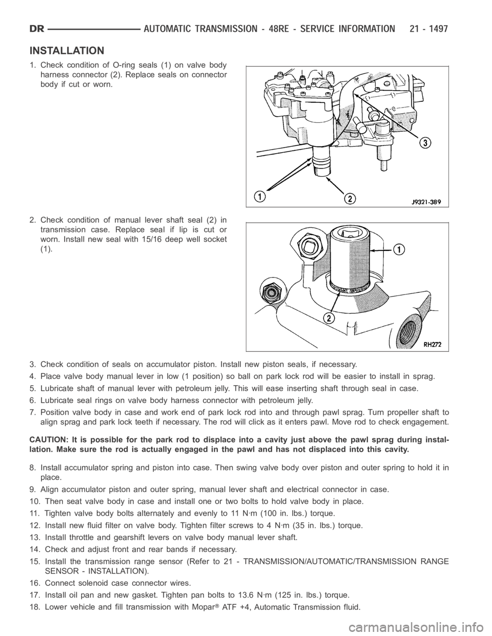
INSTALLATION
1. Check condition of O-ring seals (1) on valve body
harness connector (2). Replace seals on connector
body if cut or worn.
2. Check condition of manual lever shaft seal (2) in
transmission case. Replace seal if lip is cut or
worn. Install new seal with 15/16 deep well socket
(1).
3. Check condition of seals on accumulator piston. Install new piston seals, if necessary.
4. Place valve body manual lever in low (1 position) so ball on park lock rod will be easier to install in sprag.
5. Lubricate shaft of manual lever with petroleum jelly. This will ease inserting shaft through seal in case.
6. Lubricate seal rings on valve body harness connector with petroleum jelly.
7. Position valve body in case and work end of park lock rod into and through pawl sprag. Turn propeller shaft to
align sprag and park lock teeth if necessary. The rod will click as it enterspawl. Move rod to check engagement.
CAUTION: It is possible for the park rod to displace into a cavity just abovethe pawl sprag during instal-
lation. Make sure the rod is actually engaged in the pawl and has not displaced into this cavity.
8. Install accumulator spring and piston into case. Then swing valve body overpistonandouterspringtoholditin
place.
9. Align accumulator piston and outer spring, manual lever shaft and electrical connector in case.
10. Then seat valve body in case and install one or two bolts to hold valve bodyinplace.
11. Tighten valve body bolts alternately and evenly to 11 Nꞏm (100 in. lbs.)torque.
12. Install new fluid filter on valve body. Tighten filter screws to 4 Nꞏm (35 in. lbs.) torque.
13. Install throttle and gearshift levers on valve body manual lever shaft.
14. Check and adjust front and rear bands if necessary.
15. Install the transmission range sensor (Refer to 21 - TRANSMISSION/AUTOMATIC/TRANSMISSION RANGE
SENSOR - INSTALLATION).
16. Connect solenoid case connector wires.
17. Install oil pan and new gasket. Tighten pan bolts to 13.6 Nꞏm (125 in. lbs.) torque.
18. Lower vehicle and fill transmission with Mopar
ATF +4, Automatic Transmission fluid.
Page 4086 of 5267
A straight line shift pattern is used with a NEUTRAL detent. Lever range positions are imprinted in the shift knob.
SHIFTING
The transfer case can be shifted between the 2H and 4H operating ranges while the vehicle is in motion. The vehi-
cle must have the transmission placed in NEUTRAL, or the clutch depressed in the case of a manual transmission,
and be moving less than 2-3 MPH when shifting into and out of the 4L operatingrange.
DIAGNOSIS AND TESTING - TRANSFER CASE - NV241 GENII
Before beginning repair on a suspected transfer case malfunction, check all other driveline components beforehand.
The actual cause of a problem may be related to such items as: front hubs, axles, propeller shafts, wheels and tires,
transmission, or clutch instead. If all other driveline components are ingood condition and operating properly, refer
to the Diagnosis Chart for further information.
DIAGNOSIS CHART
Condition Possible Cause Correction
Transfer Case difficult to shift or will
not shift into desired range.1) Vehicle speed too great to permit
shifting.1) Stop vehicle and shift into
desired range. Or, reduce speed to
below 3-4 km/h (2-3 mph) before
attempting the shift.
2) If vehicle was operated for an
extended period in 4H on a dry
paved surface, the driveline torque
load may be causing a bind.2) Stop vehicle and shift the
transmission into neutral. Shift the
transfer case to 2H and operate
vehicle in 2H on dry paved
surfaces.
3) Transfer case external shift
linkage binding.3) Lubricate, repair, or replace
linkage bushings, or tighten loose
components as necessary.
4) Insufficient or incorrect lubricant. 4) Drain and refill to edge of fillhole
with Mopar
ATF +4, Automatic
Transmission fluid.
5) Internal components binding,
worn, or damaged.5) Disassemble the transfer case
and replace worn or damaged
components as necessary.
Transfer Case noisy in all operating
ranges.1) Insufficient or incorrect lubricant. 1) Drain and refill to edge of fillhole
with Mopar
ATF +4, Automatic
Transmission fluid.
Noisy in, or jumps out of, four wheel
drive low range.1) Transfer case not completely
engaged in 4L position.1) With the transmission in
NEUTRAL, or the clutch depressed
in the case of a manual
transmission and the vehicle moving
under 3-4 km/h (2-3 mph), shift the
transfer case to NEUTRAL and then
shift into the 4L position.
2) Shift linkage out of adjustment. 2) Adjust linkage.
3) Shift linkage loose or binding. 3) Tighten, lubricate, or repair
linkage as necessary.
4) Range fork damaged, inserts
worn, or fork is binding on the shift
rail.4) Disassemble unit and repair as
necessary.
5) Low range gear worn or
damaged.5) Disassemble unit and repair as
necessary.
Page 4106 of 5267
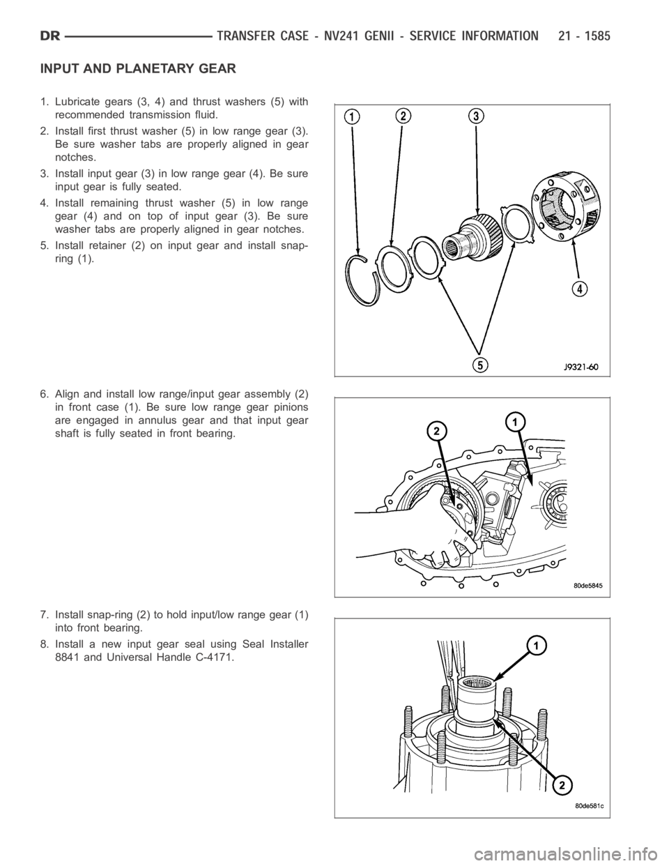
INPUT AND PLANETARY GEAR
1. Lubricate gears (3, 4) and thrust washers (5) with
recommended transmission fluid.
2. Install first thrust washer (5) in low range gear (3).
Be sure washer tabs are properly aligned in gear
notches.
3. Install input gear (3) in low range gear (4). Be sure
input gear is fully seated.
4. Install remaining thrust washer (5) in low range
gear (4) and on top of input gear (3). Be sure
washer tabs are properly aligned in gear notches.
5. Install retainer (2) on input gear and install snap-
ring (1).
6. Align and install low range/input gear assembly (2)
in front case (1). Be sure low range gear pinions
are engaged in annulus gear and that input gear
shaft is fully seated in front bearing.
7. Install snap-ring (2) to hold input/low range gear (1)
into front bearing.
8. Install a new input gear seal using Seal Installer
8841 and Universal Handle C-4171.