2006 DODGE RAM SRT-10 transmission fluid
[x] Cancel search: transmission fluidPage 3939 of 5267
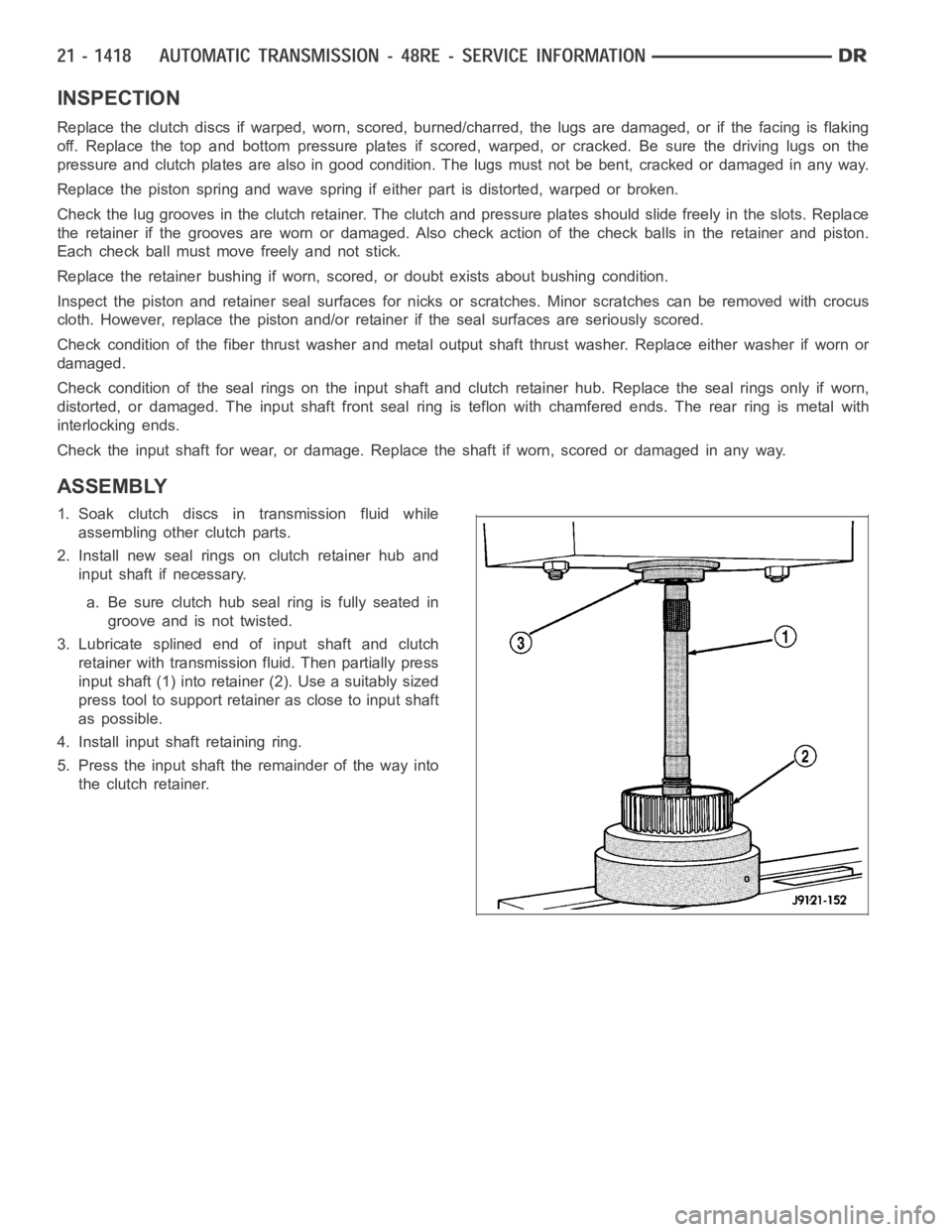
INSPECTION
Replace the clutch discs if warped, worn, scored, burned/charred, the lugs are damaged, or if the facing is flaking
off. Replace the top and bottom pressure plates if scored, warped, or cracked. Be sure the driving lugs on the
pressure and clutch plates are also in good condition. The lugs must not be bent, cracked or damaged in any way.
Replace the piston spring and wave spring if either part is distorted, warped or broken.
Check the lug grooves in the clutch retainer. The clutch and pressure plates should slide freely in the slots. Replace
the retainer if the grooves are worn or damaged. Also check action of the check balls in the retainer and piston.
Each check ball must move freely and not stick.
Replace the retainer bushing if worn, scored, or doubt exists about bushing condition.
Inspect the piston and retainer seal surfaces for nicks or scratches. Minor scratches can be removed with crocus
cloth. However, replace the piston and/or retainer if the seal surfaces are seriously scored.
Check condition of the fiber thrust washer and metal output shaft thrust washer. Replace either washer if worn or
damaged.
Check condition of the seal rings on the input shaft and clutch retainer hub. Replace the seal rings only if worn,
distorted, or damaged. The input shaft front seal ring is teflon with chamfered ends. The rear ring is metal with
interlocking ends.
Check the input shaft for wear, or damage. Replace the shaft if worn, scoredor damaged in any way.
ASSEMBLY
1. Soak clutch discs in transmission fluid while
assembling other clutch parts.
2. Install new seal rings on clutch retainer hub and
input shaft if necessary.
a. Be sure clutch hub seal ring is fully seated in
groove and is not twisted.
3. Lubricate splined end of input shaft and clutch
retainer with transmission fluid. Then partially press
input shaft (1) into retainer (2). Use a suitably sized
press tool to support retainer as close to input shaft
as possible.
4. Install input shaft retaining ring.
5. Press the input shaft the remainder of the way into
the clutch retainer.
Page 3940 of 5267
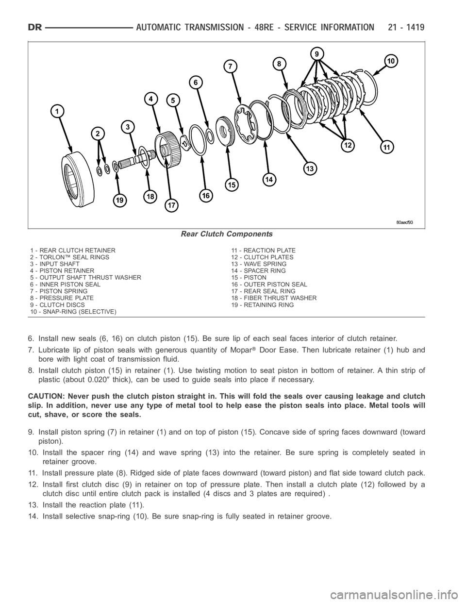
6. Install new seals (6, 16) on clutch piston (15). Be sure lip of each seal faces interior of clutch retainer.
7. Lubricate lip of piston seals with generous quantity of Mopar
Door Ease. Then lubricate retainer (1) hub and
bore with light coat of transmission fluid.
8. Install clutch piston (15) in retainer (1). Use twisting motion to seat piston in bottom of retainer. A thin strip of
plastic (about 0.020
thick), can be used to guide seals into place if necessary.
CAUTION: Never push the clutch piston straight in. This will fold the sealsover causing leakage and clutch
slip. In addition, never use any type of metal tool to help ease the piston seals into place. Metal tools will
cut, shave, or score the seals.
9. Install piston spring (7) in retainer (1) and on top of piston (15). Concave side of spring faces downward (toward
piston).
10. Install the spacer ring (14) and wave spring (13) into the retainer. Be sure spring is completely seated in
retainer groove.
11. Install pressure plate (8). Ridged side of plate faces downward (toward piston) and flat side toward clutch pack.
12. Install first clutch disc (9) in retainer on top of pressure plate. Theninstall a clutch plate (12) followed by a
clutch disc until entire clutch pack is installed (4 discs and 3 plates are required) .
13. Install the reaction plate (11).
14. Install selective snap-ring (10). Be sure snap-ring is fully seated inretainer groove.
Rear Clutch Components
1 - REAR CLUTCH RETAINER 11 - REACTION PLATE
2 - TORLON™ SEAL RINGS 12 - CLUTCH PLATES
3 - INPUT SHAFT 13 - WAVE SPRING
4 - PISTON RETAINER 14 - SPACER RING
5 - OUTPUT SHAFT THRUST WASHER 15 - PISTON
6 - INNER PISTON SEAL 16 - OUTER PISTON SEAL
7 - PISTON SPRING 17 - REAR SEAL RING
8 - PRESSURE PLATE 18 - FIBER THRUST WASHER
9 - CLUTCH DISCS 19 - RETAINING RING
10 - SNAP-RING (SELECTIVE)
Page 3942 of 5267
SERVO-REAR
DESCRIPTION
The rear (low/reverse) servo consists of a single stage or diameter pistonand a spring loaded plug. The spring is
used to cushion the application of the rear (low/reverse) band.
OPERATION
While in the de-energized state (no pressure applied), the piston is held up in its bore by the piston spring. The plug
is held down in its bore, in the piston, by the plug spring. When pressure is applied to the top of the piston, the plug
is forced down in its bore, taking up any clearance. As the piston moves, it causes the plug spring to compress, and
the piston moves down over the plug. The piston continues to move down untilit hits the shoulder of the plug and
fully applies the band. The period of time from the initial application, until the piston is against the shoulder of the
plug, represents a reduced shocking of the band that cushions the shift.
DISASSEMBLY
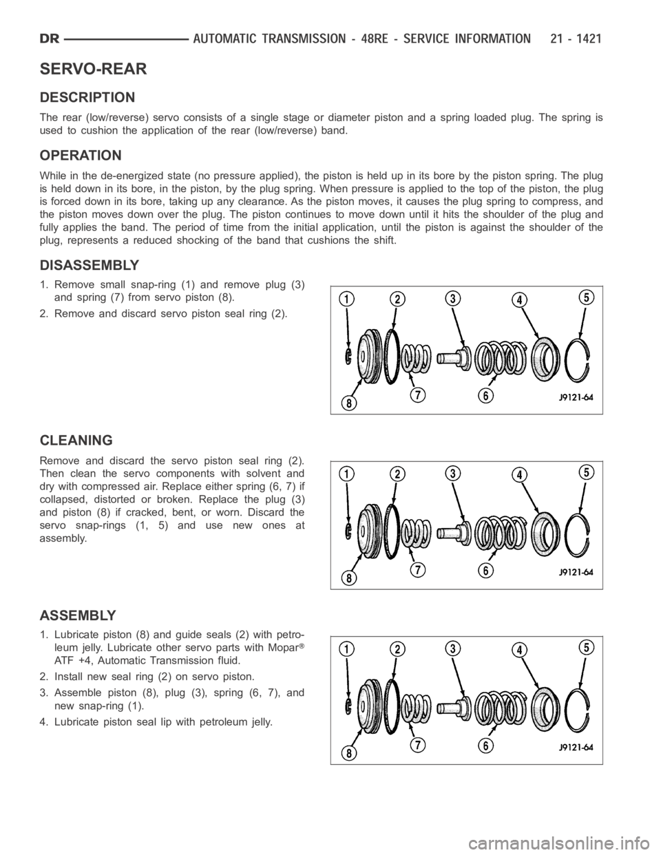
1. Remove small snap-ring (1) and remove plug (3)
and spring (7) from servo piston (8).
2. Remove and discard servo piston seal ring (2).
CLEANING
Remove and discard the servo piston seal ring (2).
Then clean the servo components with solvent and
dry with compressed air. Replace either spring (6, 7) if
collapsed, distorted or broken. Replace the plug (3)
and piston (8) if cracked, bent, or worn. Discard the
servo snap-rings (1, 5) and use new ones at
assembly.
ASSEMBLY
1. Lubricate piston (8) and guide seals (2) with petro-
leum jelly. Lubricate other servo parts with Mopar
ATF +4, Automatic Transmission fluid.
2. Install new seal ring (2) on servo piston.
3. Assemble piston (8), plug (3), spring (6, 7), and
new snap-ring (1).
4. Lubricate piston seal lip with petroleum jelly.
Page 3943 of 5267
MECHANISM-SHIFT
DESCRIPTION
The gear shift mechanism provides six shift positions which are:
PA R K ( P )
REVERSE (R)
NEUTRAL (N)
DRIVE (D)
Manual SECOND (2)
Manual LOW (1)
OPERATION
Manual LOW (1) range provides first gear only. Overrun braking is also provided in this range. Manual SECOND (2)
range provides first and second gear only.
DRIVE range provides first, second, third, and overdrive fourth gear ranges. The shift into overdrive fourth gear
range occurs only after the transmission has completed the shift into D third gear range. No further movement of the
shift mechanism is required to complete the 3-4 shift.
The fourth gear upshift occurs automatically when the overdrive selectorswitch is in the ON position. No upshift to
fourth gear will occur if any of the following are true:
The transmission fluid temperature is below 10° C (50° F) or above 121° C (250° F).
The shift to third is not yet complete.
Vehicle speed is too low for the 3-4 shift to occur.
Battery temperature is below -5° C (23° F).
Page 3952 of 5267
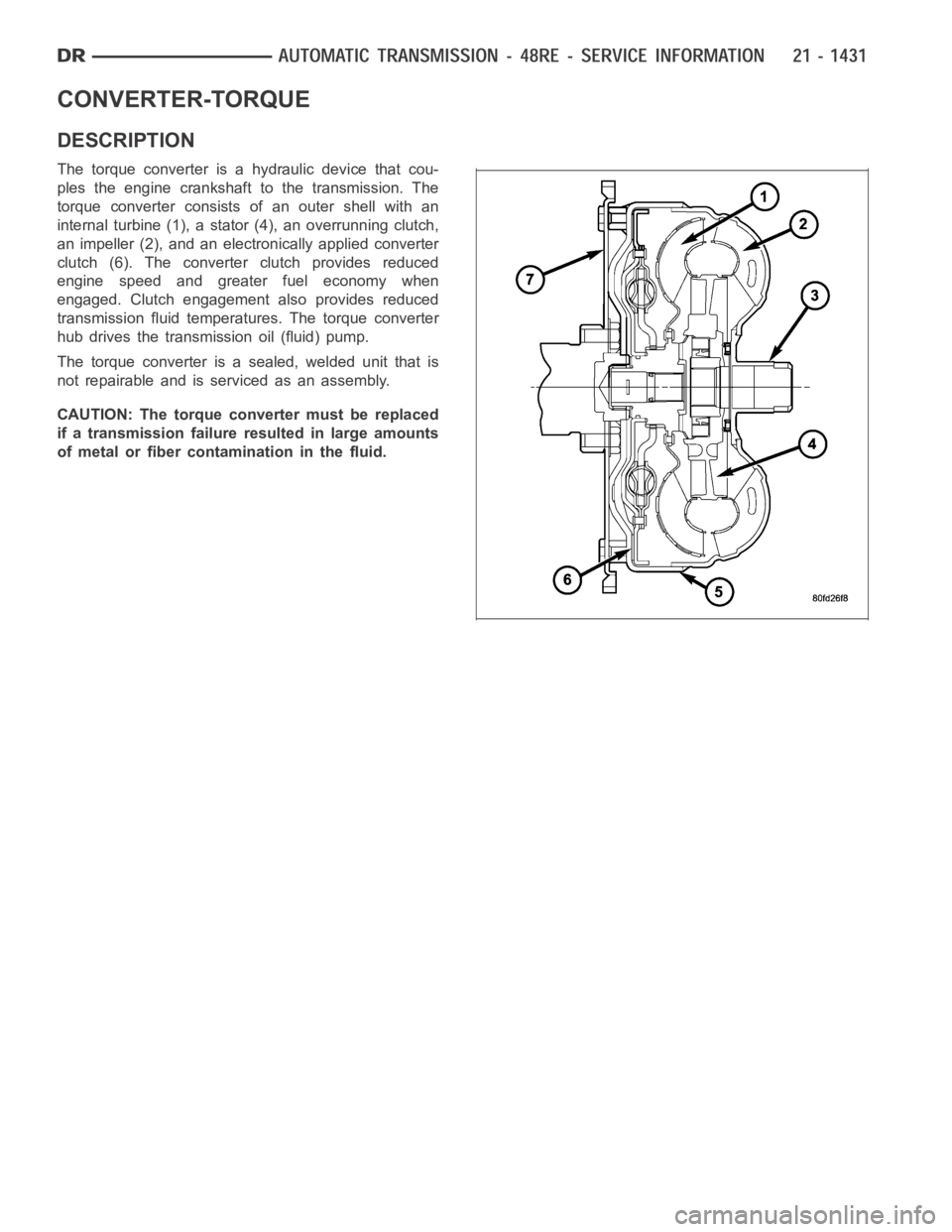
CONVERTER-TORQUE
DESCRIPTION
The torque converter is a hydraulic device that cou-
ples the engine crankshaft to the transmission. The
torque converter consists of an outer shell with an
internal turbine (1), a stator (4), an overrunning clutch,
an impeller (2), and an electronically applied converter
clutch (6). The converterclutch provides reduced
engine speed and greater fuel economy when
engaged. Clutch engagement also provides reduced
transmission fluid temperatures. The torque converter
hub drives the transmission oil (fluid) pump.
The torque converter is a sealed, welded unit that is
not repairable and is serviced as an assembly.
CAUTION: The torque converter must be replaced
if a transmission failure resulted in large amounts
of metal or fiber contamination in the fluid.
Page 3956 of 5267
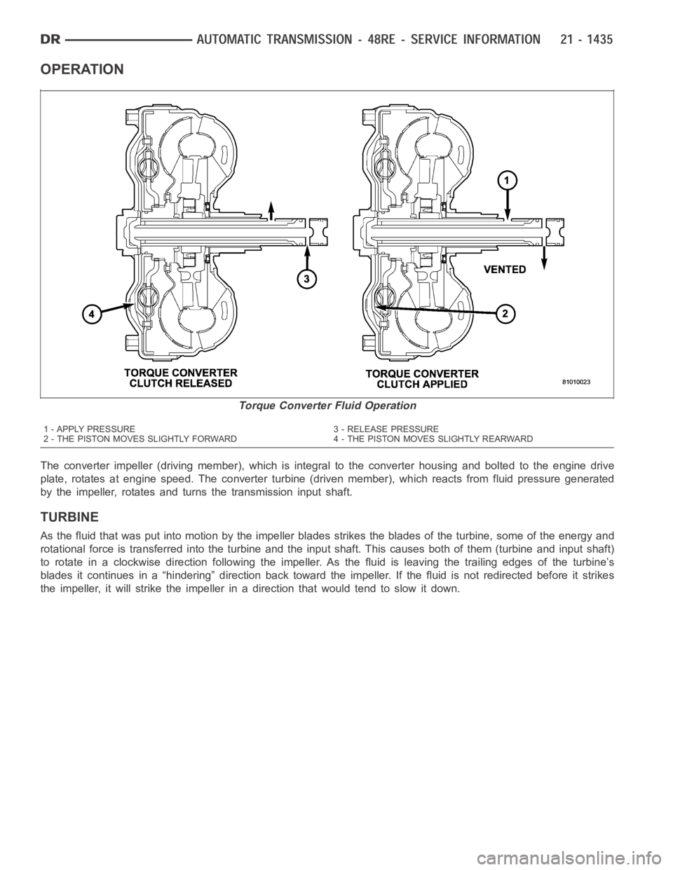
OPERATION
The converter impeller (driving member), which is integral to the converter housing and bolted to the engine drive
plate, rotates at engine speed. The converter turbine (driven member), which reacts from fluid pressure generated
by the impeller, rotates and turns the transmission input shaft.
TURBINE
As the fluid that was put into motion bythe impeller blades strikes the blades of the turbine, some of the energy and
rotational force is transferred into the turbine and the input shaft. Thiscauses both of them (turbine and input shaft)
to rotate in a clockwise direction following the impeller. As the fluid is leaving the trailing edges of the turbine’s
blades it continues in a “hindering” direction back toward the impeller. If the fluid is not redirected before it strikes
the impeller, it will strike the impeller in a direction that would tend to slow it down.
Torque Converter Fluid Operation
1 - APPLY PRESSURE 3 - RELEASE PRESSURE
2 - THE PISTON MOVES SLIGHTLY FORWARD 4 - THE PISTON MOVES SLIGHTLY REARWARD
Page 3957 of 5267
STATOR
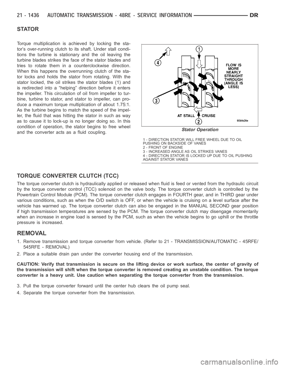
Torque multiplication is achieved by locking the sta-
tor’s over-running clutch to its shaft. Under stall condi-
tions the turbine is stationary and the oil leaving the
turbine blades strikes the face of the stator blades and
tries to rotate them in a counterclockwise direction.
When this happens the overrunning clutch of the sta-
tor locks and holds the stator from rotating. With the
stator locked, the oil strikes the stator blades (1) and
is redirected into a “helping” direction before it enters
the impeller. This circulation of oil from impeller to tur-
bine, turbine to stator, and stator to impeller, can pro-
duce a maximum torque multiplication of about 1.75:1.
As the turbine begins to match the speed of the impel-
ler, the fluid that was hitting the stator in such as way
as to cause it to lock-up is no longer doing so. In this
condition of operation, the stator begins to free wheel
and the converter acts as a fluid coupling.
TORQUE CONVERTER CLUTCH (TCC)
The torque converter clutch is hydraulically applied or released when fluid is feed or vented from the hydraulic circuit
by the torque converter control (TCC) solenoid on the valve body. The torque converter clutch is controlled by the
Powertrain Control Module (PCM). The torque converter clutch engages in FOURTH gear, and in THIRD gear under
various conditions, such as when the O/D switch is OFF, or when the vehicle is cruising on a level surface after the
vehicle has warmed up. The torque converter clutch can also be engaged in the MANUAL SECOND gear position
if high transmission temperatures are sensed by the PCM. The torque converter clutch may disengage momentarily
when an increase in engine load is sensed by the PCM, such as when the vehiclebegins to go uphill or the throttle
pressure is increased.
REMOVAL
1. Remove transmission and torque converter from vehicle. (Refer to 21 - TRANSMISSION/AUTOMATIC - 45RFE/
545RFE - REMOVAL)
2. Place a suitable drain pan under the converter housing end of the transmission.
CAUTION: Verify that transmission is secure on the lifting device or work surface, the center of gravity of
the transmission will shift when the torque converter is removed creatingan unstable condition. The torque
converter is a heavy unit. Use caution when separating the torque converter from the transmission.
3. Pull the torque converter forward until the center hub clears the oil pumpseal.
4. Separate the torque converter from the transmission.
Stator Operation
1 - DIRECTION STATOR WILL FREE WHEEL DUE TO OIL
PUSHING ON BACKSIDE OF VANES
2-FRONTOFENGINE
3 - INCREASED ANGLE AS OIL STRIKES VANES
4 - DIRECTION STATOR IS LOCKED UP DUE TO OIL PUSHING
AGAINST STATOR VANES
Page 3958 of 5267
INSTALLATION
Check converter hub and drive notches for sharp
edges, burrs, scratches, or nicks. Polish the hub and
notches with 320/400 grit paper or crocus cloth if nec-
essary. The hub must be smooth to avoid damaging
the pump seal at installation.
1. Lubricate oil pump seal lip with transmission fluid.
2. Place torque converter in position on transmission.
CAUTION: Do not damage oil pump seal or bush-
ing while inserting torqueconverterintothefront
of the transmission.
3. Align torque converter to oil pump seal opening.
4. Insert torque converter hub into oil pump.
5. While pushing torque converter inward, rotate con-
verter until converter is fully seated in the oil pump
gears.
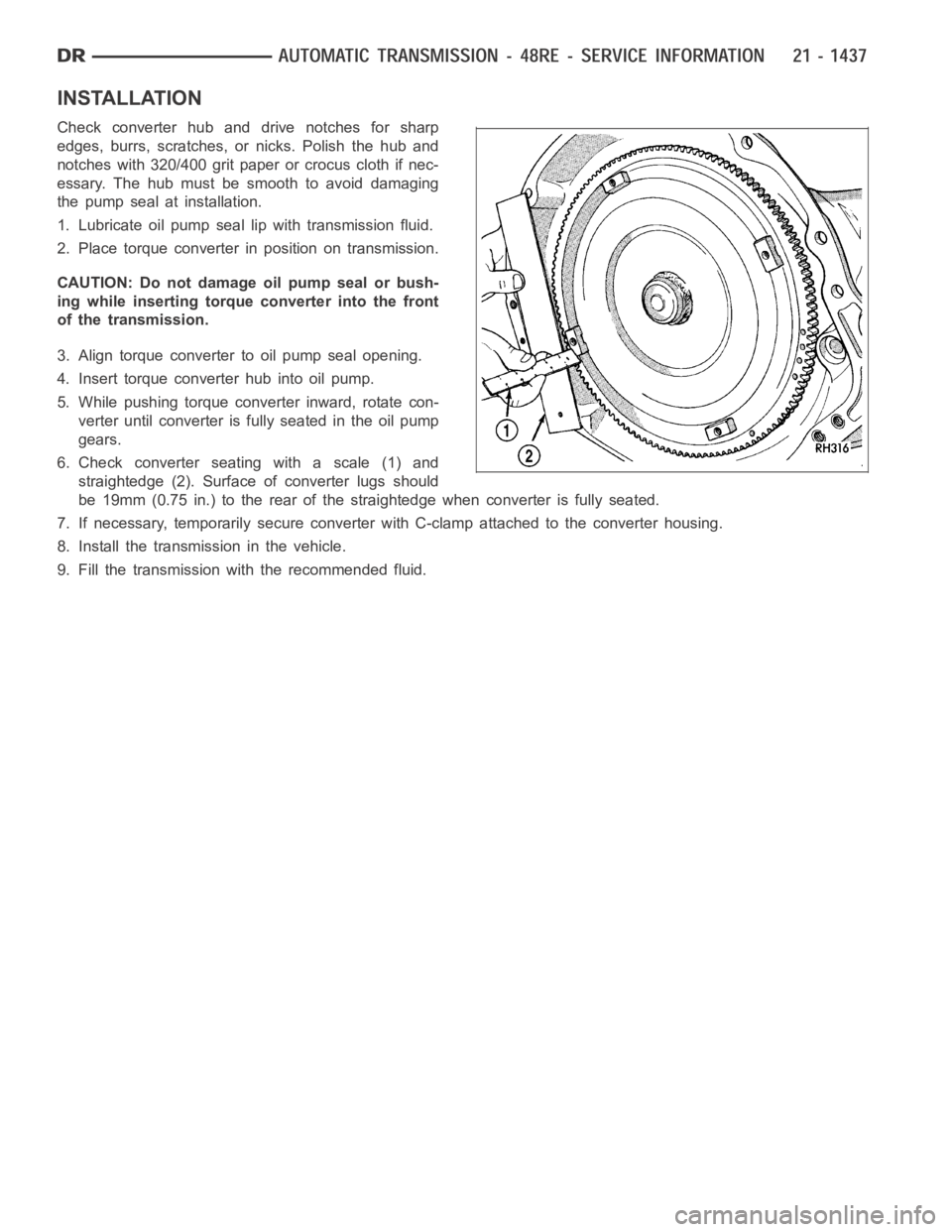
6. Check converter seating with a scale (1) and
straightedge (2). Surface of converter lugs should
be 19mm (0.75 in.) to the rear of the straightedge when converter is fully seated.
7. If necessary, temporarily secure converter with C-clamp attached to the converter housing.
8. Install the transmission in the vehicle.
9. Fill the transmission with the recommended fluid.