Page 4107 of 5267
SHIFT FORKS AND MAINSHAFT
1. Lubricate mainshaft splines with recommended
transmission fluid.
2. Install the mode hub (1) onto the output shaft.
3. Install the mode hub retaining ring (2) onto the out-
put shaft (1).
4. Install the sprocket hub (2) onto the output shaft
(1).
Page 4109 of 5267
8. Install the drive sprocket retaining ring (2) onto the
output shaft (1).
9. Lubricate sector shaft with transmission fluid and
install shift sector (1) in case. Position slot in sector
so it will be aligned with shift fork pin when shift
forks are installed.
10. Install the shift sector support (1). Tighten the sec-
tor support to 27-42 Nꞏm (20-30 ft.lbs.).
Page 4115 of 5267

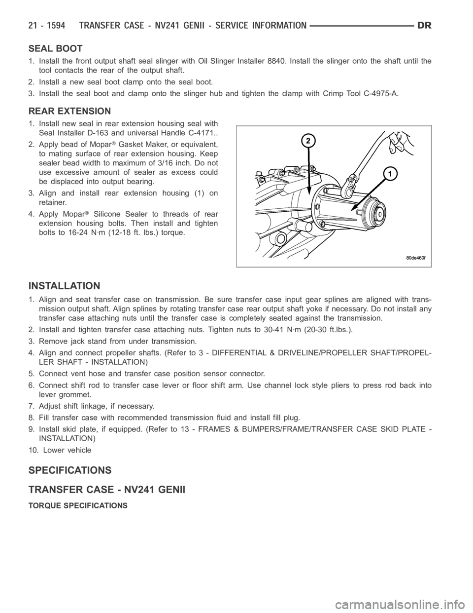
SEAL BOOT
1. Install the front output shaft seal slinger with Oil Slinger Installer 8840. Install the slinger onto the shaft until the
tool contacts the rear of the output shaft.
2. Install a new seal boot clamp onto the seal boot.
3. Install the seal boot and clamp onto the slinger hub and tighten the clampwith Crimp Tool C-4975-A.
REAR EXTENSION
1. Install new seal in rear extension housing seal with
Seal Installer D-163 and universal Handle C-4171..
2. Apply bead of Mopar
Gasket Maker, or equivalent,
to mating surface of rear extension housing. Keep
sealer bead width to maximum of 3/16 inch. Do not
use excessive amount of sealer as excess could
be displaced into output bearing.
3. Align and install rear extension housing (1) on
retainer.
4. Apply Mopar
Silicone Sealer to threads of rear
extension housing bolts. Then install and tighten
bolts to 16-24 Nꞏm (12-18 ft. lbs.) torque.
INSTALLATION
1. Align and seat transfer case on transmission. Be sure transfer case input gear splines are aligned with trans-
mission output shaft. Align splines by rotating transfer case rear outputshaft yoke if necessary. Do not install any
transfer case attaching nuts until the transfer case is completely seatedagainst the transmission.
2. Install and tighten transfer case attaching nuts. Tighten nuts to 30-41Nꞏm (20-30 ft.lbs.).
3. Remove jack stand from under transmission.
4. Align and connect propeller shafts. (Refer to 3 - DIFFERENTIAL & DRIVELINE/PROPELLER SHAFT/PROPEL-
LER SHAFT - INSTALLATION)
5. Connect vent hose and transfer case position sensor connector.
6. Connect shift rod to transfer case lever or floor shift arm. Use channel lock style pliers to press rod back into
lever grommet.
7. Adjust shift linkage, if necessary.
8. Fill transfer case with recommended transmission fluid and install fillplug.
9. Install skid plate, if equipped. (Refer to 13 - FRAMES & BUMPERS/FRAME/TRANSFER CASE SKID PLATE -
INSTALLATION)
10. Lower vehicle
SPECIFICATIONS
TRANSFER CASE - NV241 GENII
TORQUE SPECIFICATIONS
Page 4120 of 5267
FLUID
STANDARD PROCEDURE - FLUID DRAIN AND REFILL
The fill (2) and drain (3) plugs are both in the rear
case.
1. Raise vehicle.
2. Position drain pan under transfer case.
NOTE: It may be necessary to remove the exhaust
y-pipe at the exhaust manifold to properly access
the fill and drain plugs. Lowering the exhaust will
allow the plugs to be accessed for torquing during
installation. (Refer to 11 - EXHAUST SYSTEM/EX-
HAUST PIPE - REMOVAL)
3. Remove drain and fill plugs and drain lubricant
completely.
4. Install drain plug. Tighten plug to 20-34 Nꞏm (15-25
ft. lbs.).
5. Remove drain pan.
6. Fill transfer case to bottom edge of fill plug opening with Mopar
ATF +4, Automatic Transmission fluid.
7. Install and tighten fill plug to 20-34 Nꞏm (15-25 ft. lbs.).
8. Install the exhaust y-pipe to the exhaust manifold, if removed. (Refer to 11 - EXHAUST SYSTEM/EXHAUST
PIPE - INSTALLATION)
9. Wipe any excess fluid that mayhave spilled onto the exhaust.
10. Lower vehicle.
Page 4128 of 5267

A straight line shift pattern is used with a NEUTRAL detent. Lever range positions are imprinted in the shift knob.
SHIFTING
The transfer case can be shifted between the 2H and 4H operating ranges while the vehicle is in motion. The vehi-
cle must have the transmission placed in NEUTRAL, or the clutch depressed in the case of a manual transmission,
and be moving less than 2-3 MPH when shifting into and out of the 4L operatingrange.
DIAGNOSIS AND TESTING - TRANSFER CASE - NV271
Before beginning repair on a suspected transfer case malfunction, check all other driveline components beforehand.
The actual cause of a problem may be related to such items as: front hubs, axles, propeller shafts, wheels and tires,
transmission, or clutch instead. If all other driveline components are ingood condition and operating properly, refer
to the Diagnosis Chart for further information.
DIAGNOSIS CHART
Condition Possible Cause Correction
Transfer Case difficult to shift or will
not shift into desired range.1) Vehicle speed too great to permit
shifting.1) Stop vehicle and shift into
desired range. Or, reduce speed to
below 3-4 km/h (2-3 mph) before
attempting the shift.
2) If vehicle was operated for an
extended period in 4H on a dry
paved surface, the driveline torque
load may be causing a bind.2) Stop vehicle and shift the
transmission into neutral. Shift the
transfer case to 2H and operate
vehicle in 2H on dry paved
surfaces.
3) Transfer case external shift
linkage binding.3) Lubricate, repair, or replace
linkage bushings, or tighten loose
components as necessary.
4) Insufficient or incorrect lubricant. 4) Drain and refill to edge of fillhole
with Mopar
ATF +4, Automatic
Transmission fluid.
5) Internal components binding,
worn, or damaged.5) Disassemble the transfer case
and replace worn or damaged
components as necessary.
Transfer Case noisy in all operating
ranges.1) Insufficient or incorrect lubricant. 1) Drain and refill to edge of fillhole
with Mopar
ATF +4, Automatic
Transmission fluid.
Noisy in, or jumps out of, four wheel
drive low range.1) Transfer case not completely
engaged in 4L position.1) With the transmission in
NEUTRAL, or the clutch depressed
in the case of a manual
transmission and the vehicle moving
under 3-4 km/h (2-3 mph), shift the
transfer case to NEUTRAL and then
shift into the 4L position.
2) Shift linkage out of adjustment. 2) Adjust linkage.
3) Shift linkage loose or binding. 3) Tighten, lubricate, or repair
linkage as necessary.
4) Range fork damaged, inserts
worn, or fork is binding on the shift
rail.4) Disassemble unit and repair as
necessary.
5) Low range gear worn or
damaged.5) Disassemble unit and repair as
necessary.
Page 4152 of 5267
18. Install the rear output shaft bearing into the rear
case (1) using Seal Installer 8152 (3) and Univer-
sal Handle C-4171 (2).
19. Install the rear output shaft bearing snap-ring into
the rear case half.
INPUT AND PLANETARY GEAR
1. Lubricate gears and thrust washers with recom-
mended transmission fluid.
2. Install bottom thrust washer (2) in low range gear
planetary (1). Be sure washer tabs are properly
aligned in gear notches.
Page 4155 of 5267
SHIFT FORKS AND MAINSHAFT
1. Lubricate mainshaft splines with recommended
transmission fluid.
2. Coat the interior of the drive sprocket hub with
ATF+4 and install the drive sprocket drive hub (2)
onto the mainshaft (1).
3. Install the mode hub (2) onto the mainshaft (1).
Page 4156 of 5267
4. Install the mode hub retaining ring (3) onto the
mainshaft (1).
5. Install the clutch gear (2) onto the output shaft (1).
Verify that the pointed ends of the clutch gear teeth
are pointing to the front of the mainshaft.
6. Lubricate sector shaft with transmission fluid and
install shift sector (1) in case. Position slot in sector
so it will be aligned with shift fork pin when shift
forks are installed.
7. Apply Loctite™ 242, or equivalent, to the threads of
the sector support to replenish the factory applied
patch. Install the shift sector support. Tighten the
sector support with Socket 9033 to 27-34 Nꞏm
(20-25 ft.lbs.).