Page 3959 of 5267
VALVE-TORQUE CONVERTER DRAINBACK
DESCRIPTION
GAS ENGINES
The drainback valve is located in the transmission cooler outlet (pressure) line.
DIESEL ENGINE
The converter drainback check valve is located in the in the TOC pressure - supply line, between the engine
mounted TOC and the air to oil TOC.
OPERATION
GAS ENGINES
The valve prevents fluid from draining from the converter into the cooler and lines when the vehicle is shut down for
lengthy periods. Production valves have a hose nipple at one end, while theopposite end is threaded for a flare
fitting. All valves have an arrow (or similar mark) to indicate direction of flow through the valve.
DIESEL ENGINE
The valve prevents fluid from draining from the converter into the cooler and lines when the vehicle is shut down for
lengthy periods. Production valves have pipe thread on one end, while the opposite end is threaded for a flare
fitting, and are threaded into the oil cooler mounted on the side of the engine. All valves have an arrow (or similar
mark) to indicate direction of flow through the valve.
STANDARD PROCEDURE
GAS ENGINES
The converter drainback check valve is located in the cooler outlet (pressure) line near the radiator tank. The valve
prevents fluid drainback when the vehicle is parked for lengthy periods. The valve check ball is spring loaded and
has an opening pressure of approximately 2 psi.
The valve is serviced as an assembly; it is not repairable. Do not clean the valve if restricted, or contaminated by
sludge, or debris. If the valve fails, or if a transmission malfunction occurs that generates significant amounts of
sludge and/or clutch particles and metal shavings, the valve must be replaced.
If the valve is restricted, installed backwards, or in the wrong line, it will cause an transmission overheating condition
and possible transmission failure.
CAUTION: The drainback valve is a one-way flow device. It must be properly orientedintermsofflowdirec-
tion for the cooler to function properly. The valve must be installed in thepressure line. Otherwise flow will
be blocked and would cause an transmission overheating condition and eventual transmission failure.
DIESEL ENGINE
The converter drainback check valve is located in the in the TOC pressure - supply line, between the engine
mounted transmission oil cooler and the air to oil transmission oil cooler. The valve prevents fluid drainback when
the vehicle is parked for lengthy periods. The valve check ball is spring loaded and has an opening pressure of
approximately 2 psi.
The valve is serviced as an assembly; it is not repairable. Do not clean the valve if restricted, or contaminated by
sludge, or debris. If the valve fails, or if a transmission malfunction occurs that generates significant amounts of
sludge and/or clutch particles and metal shavings, the valve must be replaced.
If the valve is restricted, installed backwards, or in the wrong line, it will cause an transmission overheating condition
and possible transmission failure.
Page 3967 of 5267
3. Install the TRS (3) into the mounting bracket (2)
with the wiring connector facing the front of the
transmission.
4. Install the two screws to hold the TRS to the
mounting bracket. Tighten the screws to 5 Nꞏm (45
in.lbs.).
5. Verify proper sensor operation (1-4).
6. Move the transmission manual shaft lever to the
PARK position.
7. Connect TRS wiring connector to the TRS and
lower vehicle.
8. Refill the transmission fluid to the correct level.
1 - NEUTRAL CONTACT
2 - MANUAL LEVER AND SENSOR PLUNGER IN REVERSE
POSITION
3 - PARK CONTACT
4 - TRANSMISSION RANGE SENSOR
Page 3968 of 5267
SENSOR-TRANSMISSION TEMPERATURE
DESCRIPTION
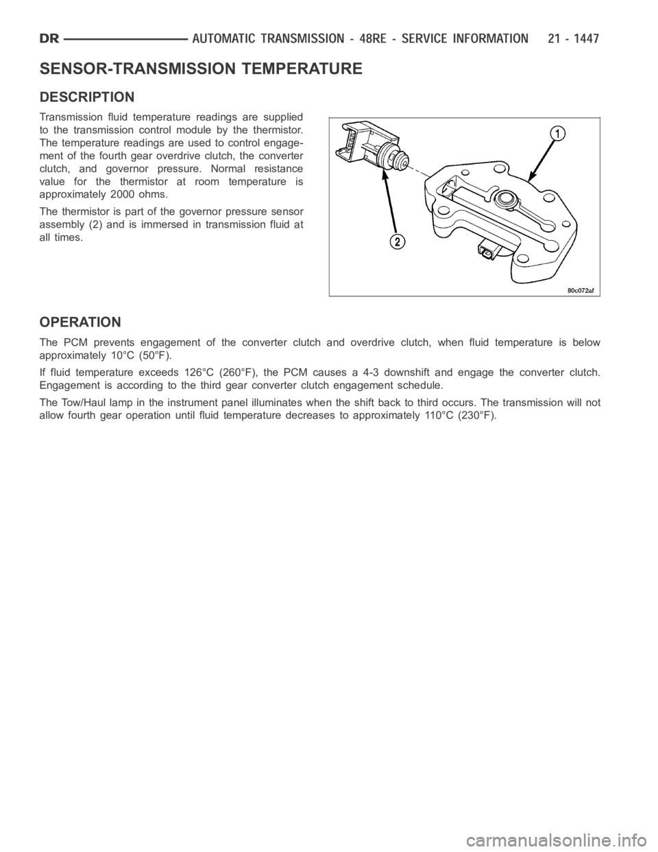
Transmission fluid temperature readings are supplied
to the transmission control module by the thermistor.
The temperature readings are used to control engage-
ment of the fourth gear overdrive clutch, the converter
clutch, and governor pressure. Normal resistance
value for the thermistor at room temperature is
approximately 2000 ohms.
The thermistor is part of the governor pressure sensor
assembly (2) and is immersed in transmission fluid at
all times.
OPERATION
The PCM prevents engagement of the converter clutch and overdrive clutch,when fluid temperature is below
approximately 10°C (50°F).
If fluid temperature exceeds 126°C (260°F), the PCM causes a 4-3 downshiftand engage the converter clutch.
Engagement is according to the third gear converter clutch engagement schedule.
The Tow/Haul lamp in the instrument panel illuminates when the shift back to third occurs. The transmission will not
allow fourth gear operation until fluid temperature decreases to approximately 110°C (230°F).
Page 3969 of 5267
BODY-VALVE
DESCRIPTION
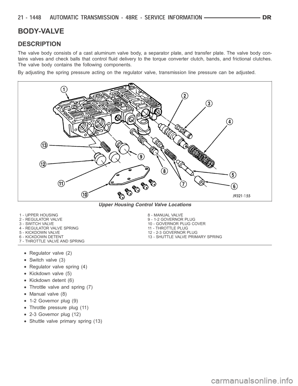
The valve body consists of a cast aluminum valve body, a separator plate, and transfer plate. The valve body con-
tains valves and check balls that control fluid delivery to the torque converter clutch, bands, and frictional clutches.
The valve body contains the following components.
By adjusting the spring pressure acting on the regulator valve, transmission line pressure can be adjusted.
Regulator valve (2)
Switch valve (3)
Regulator valve spring (4)
Kickdown valve (5)
Kickdown detent (6)
Throttle valve and spring (7)
Manual valve (8)
1-2 Governor plug (9)
Throttlepressureplug(11)
2-3 Governor plug (12)
Shuttle valve primary spring (13)
Upper Housing Control Valve Locations
1 - UPPER HOUSING 8 - MANUAL VALVE
2 - REGULATOR VALVE 9 - 1-2 GOVERNOR PLUG
3 - SWITCH VALVE 10 - GOVERNOR PLUG COVER
4 - REGULATOR VALVE SPRING 11 - THROTTLE PLUG
5 - KICKDOWN VALVE 12 - 2-3 GOVERNOR PLUG
6 - KICKDOWN DETENT 13 - SHUTTLE VALVE PRIMARY SPRING
7 - THROTTLE VALVE AND SPRING
Page 3975 of 5267
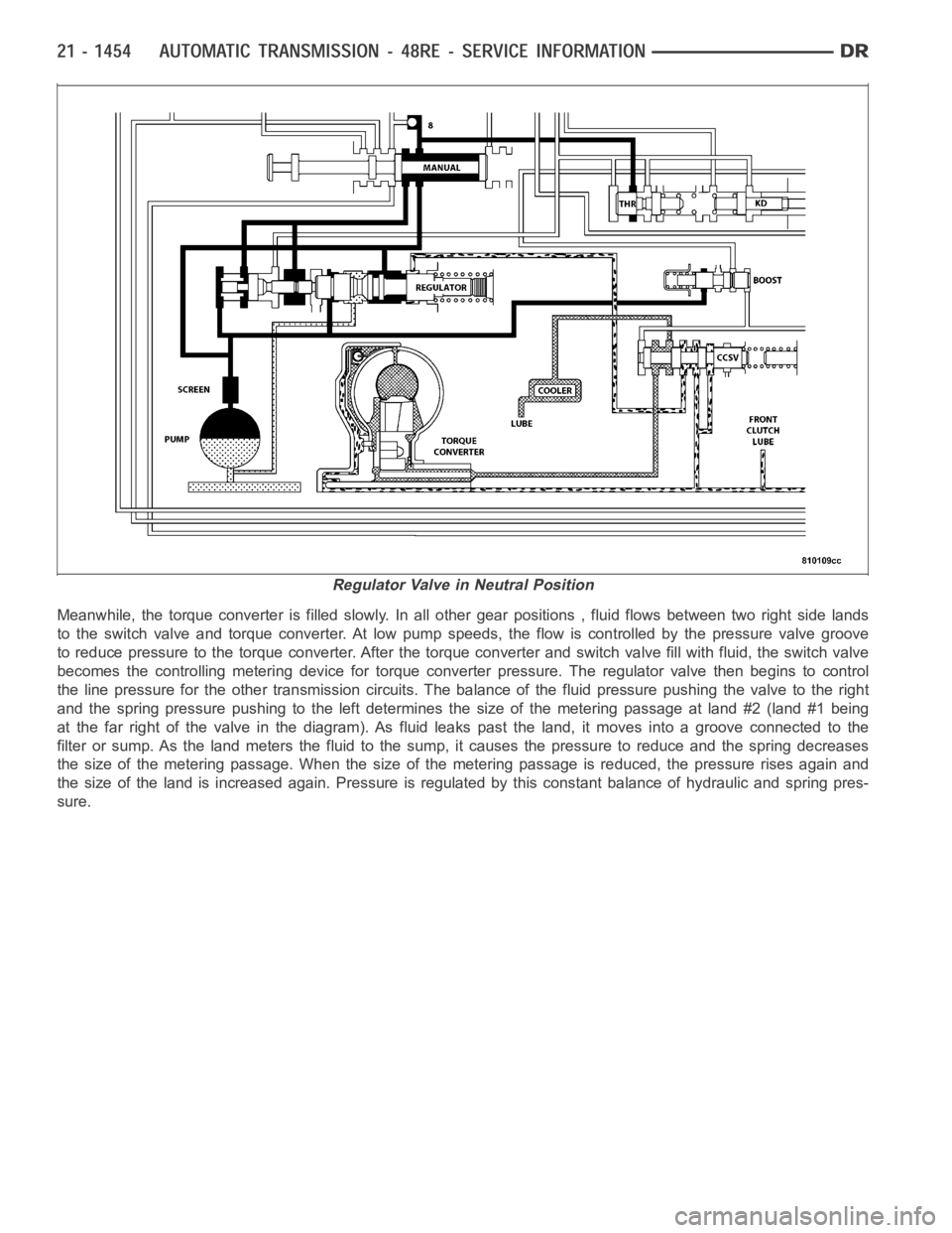
Meanwhile, the torque converter is filled slowly. In all other gear positions , fluid flows between two right side lands
to the switch valve and torque converter. At low pump speeds, the flow is controlled by the pressure valve groove
to reduce pressure to the torque converter. After the torque converter andswitch valve fill with fluid, the switch valve
becomes the controlling metering device for torque converter pressure. The regulator valve then begins to control
the line pressure for the other transmission circuits. The balance of the fluid pressure pushing the valve to the right
and the spring pressure pushing to the left determines the size of the metering passage at land #2 (land #1 being
at the far right of the valve in the diagram). As fluid leaks past the land, itmoves into a groove connected to the
filter or sump. As the land meters the fluid to the sump, it causes the pressure to reduce and the spring decreases
the size of the metering passage. When the size of the metering passage is reduced, the pressure rises again and
the size of the land is increased again. Pressure is regulated by this constant balance of hydraulic and spring pres-
sure.
Regulator Valve in Neutral Position
Page 3989 of 5267
SWITCH VALVE
When the transmission is in Drive Second before the TCC application occurs, the pressure regulator valve is sup-
plying torque converter pressure to the switch valve. The switch valve directs this pressure through the transmission
input shaft, into the converter, through the converter, back out between the input shaft and the reaction shaft, and
back up to the switch valve. From the switch valve, the fluid pressure is directed to the transmission cooler, and
lubrication pressure returns from the cooler to lubricate different portions of the transmission.
Switch Valve - Torque Converter Unlocked
Page 3991 of 5267
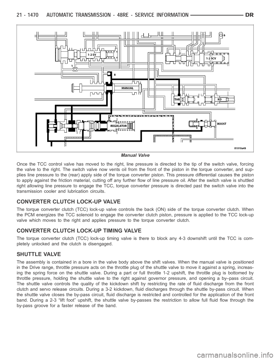
Once the TCC control valve has moved to the right, line pressure is directedto the tip of the switch valve, forcing
the valve to the right. The switch valve now vents oil from the front of the piston in the torque converter, and sup-
plies line pressure to the (rear) apply side of the torque converter piston. This pressure differential causes the piston
to apply against the friction material, cutting off any further flow of line pressure oil. After the switch valve is shuttled
right allowing line pressure to engage the TCC, torque converter pressureis directed past the switch valve into the
transmission cooler and lubrication circuits.
CONVERTER CLUTCH LOCK-UP VALVE
The torque converter clutch (TCC) lock-up valve controls the back (ON) side of the torque converter clutch. When
the PCM energizes the TCC solenoid to engage the converter clutch piston, pressure is applied to the TCC lock-up
valve which moves to the right and applies pressure to the torque converterclutch.
CONVERTER CLUTCH LOCK-UP TIMING VALVE
The torque converter clutch (TCC) lock-up timing valve is there to block any 4-3 downshift until the TCC is com-
pletely unlocked and the clutch is disengaged.
SHUTTLE VALVE
The assembly is contained in a bore in the valve body above the shift valves.When the manual valve is positioned
in the Drive range, throttle pressure acts on the throttle plug of the shuttle valve to move it against a spring, increas-
ing the spring force on the shuttle valve. During a part or full throttle 1-2upshift, the throttle plug is bottomed by
throttle pressure, holding the shuttle valve to the right against governor pressure, and opening a by–pass circuit.
The shuttle valve controls the quality of the kickdown shift by restricting the rate of fluid discharge from the front
clutch and servo release circuits. During a 3-2 kickdown, fluid discharges through the shuttle by-pass circuit. When
the shuttle valve closes the by-pass circuit, fluid discharge is restricted and controlled for the application of the front
band. During a 2-3 “lift foot” upshift, the shuttle valve by-passes the restriction to allow full fluid flow through the
by-pass groove for a faster release of the band.
Manual Valve
Page 3992 of 5267
BOOST VALVE
The boost valve provides increased fluid apply pres-
sure to the overdrive clutch during 3-4 upshifts, and
when accelerating in fourth gear.
Theboostvalvealsoservestoincreaselinepressure
during torque converter lock-up.
REMOVAL
The valve body can be removed for service without having to remove the transmission assembly.
The valve body can be disassembled for cleaning and inspection of the individual components.
The only replaceable valve body components are:
Manual lever.
Manual lever washer, seal, E-clip, and shaft seal.
Boost Valve Before Lock-up
Boost Valve After Lock-up