2006 DODGE RAM SRT-10 transmission fluid
[x] Cancel search: transmission fluidPage 3890 of 5267
PUMP-OIL
DESCRIPTION
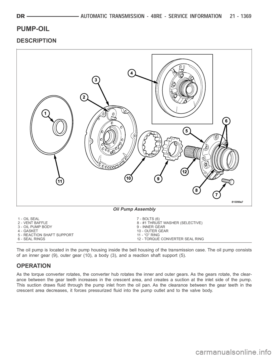
The oil pump is located in the pump housing inside the bell housing of the transmission case. The oil pump consists
of an inner gear (9), outer gear (10), a body (3), and a reaction shaft support(5).
OPERATION
As the torque converter rotates, the converter hub rotates the inner and outer gears. As the gears rotate, the clear-
ance between the gear teeth increases in the crescent area, and creates a suction at the inlet side of the pump.
This suction draws fluid through the pump inlet from the oil pan. As the clearance between the gear teeth in the
crescent area decreases, it forces pressurized fluid into the pump outletand to the valve body.
Oil Pump Assembly
1 - OIL SEAL 7 - BOLTS (6)
2 - VENT BAFFLE 8 - #1 THRUST WASHER (SELECTIVE)
3 - OIL PUMP BODY 9 - INNER GEAR
4 - GASKET 10 - OUTER GEAR
5 - REACTION SHAFT SUPPORT 11 - “O” RING
6 - SEAL RINGS 12 - TORQUE CONVERTER SEAL RING
Page 3894 of 5267
ASSEMBLY
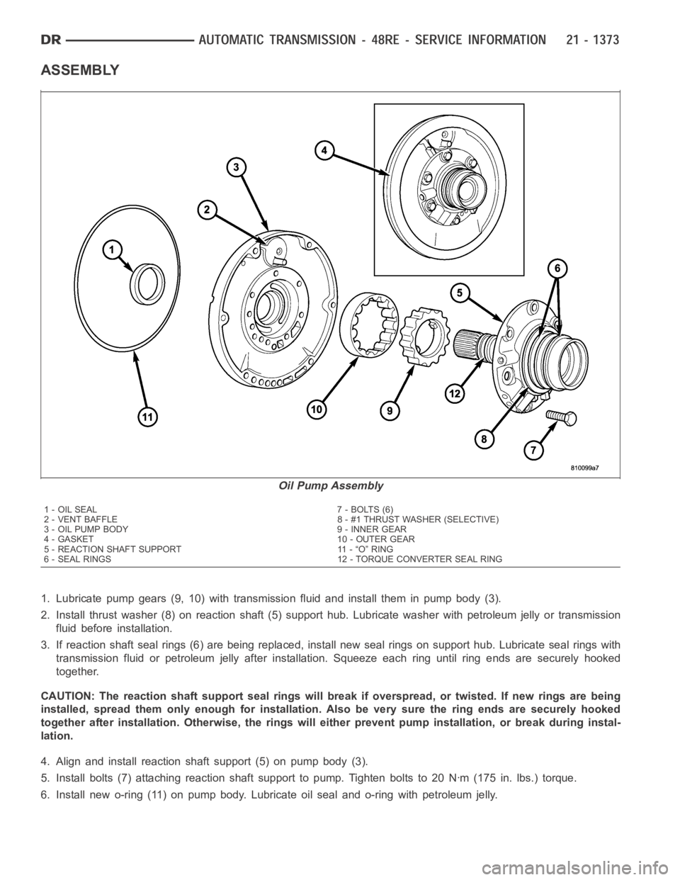
1. Lubricate pump gears (9, 10) with transmission fluid and install them inpump body (3).
2. Install thrust washer (8) on reaction shaft (5) support hub. Lubricate washer with petroleum jelly or transmission
fluid before installation.
3. If reaction shaft seal rings (6) are being replaced, install new seal rings on support hub. Lubricate seal rings with
transmission fluid or petroleum jelly after installation. Squeeze each ring until ring ends are securely hooked
together.
CAUTION: The reaction shaft support seal rings will break if overspread, or twisted. If new rings are being
installed, spread them only enough forinstallation. Also be very sure thering ends are securely hooked
together after installation. Otherwise, the rings will either prevent pump installation, or break during instal-
lation.
4. Align and install reaction shaft support (5) on pump body (3).
5. Install bolts (7) attaching reaction shaft support to pump. Tighten bolts to 20 Nꞏm (175 in. lbs.) torque.
6. Install new o-ring (11) on pump body. Lubricate oil seal and o-ring with petroleum jelly.
Oil Pump Assembly
1 - OIL SEAL 7 - BOLTS (6)
2 - VENT BAFFLE 8 - #1 THRUST WASHER (SELECTIVE)
3 - OIL PUMP BODY 9 - INNER GEAR
4 - GASKET 10 - OUTER GEAR
5 - REACTION SHAFT SUPPORT 11 - “O” RING
6 - SEAL RINGS 12 - TORQUE CONVERTER SEAL RING
Page 3898 of 5267
CLUTCH-OVERDRIVE
DESCRIPTION
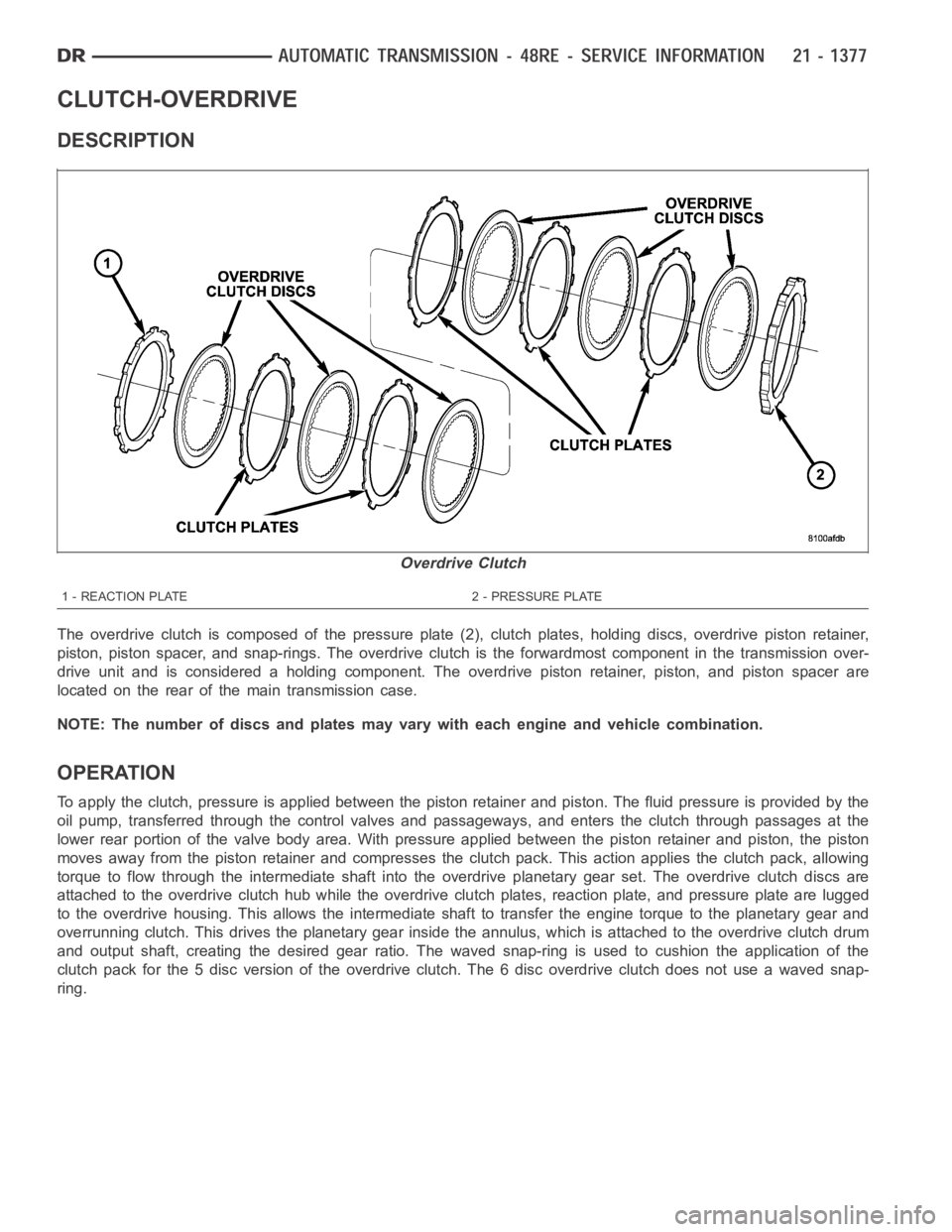
The overdrive clutch is composed of the pressure plate (2), clutch plates,holding discs, overdrive piston retainer,
piston, piston spacer, and snap-rings. The overdrive clutch is the forwardmost component in the transmission over-
drive unit and is considered a holding component. The overdrive piston retainer, piston, and piston spacer are
located on the rear of the main transmission case.
NOTE: The number of discs and plates may vary with each engine and vehicle combination.
OPERATION
To apply the clutch, pressure is applied between the piston retainer and piston. The fluid pressure is provided by the
oil pump, transferred through the control valves and passageways, and enters the clutch through passages at the
lower rear portion of the valve body area. With pressure applied between the piston retainer and piston, the piston
moves away from the piston retainer and compresses the clutch pack. This action applies the clutch pack, allowing
torque to flow through the intermediate shaft into the overdrive planetary gear set. The overdrive clutch discs are
attached to the overdrive clutch hub while the overdrive clutch plates, reaction plate, and pressure plate are lugged
to the overdrive housing. This allows the intermediate shaft to transfer the engine torque to the planetary gear and
overrunning clutch. This drives the planetary gear inside the annulus, which is attached to the overdrive clutch drum
and output shaft, creating the desired gear ratio. The waved snap-ring is used to cushion the application of the
clutch pack for the 5 disc version of the overdrive clutch. The 6 disc overdrive clutch does not use a waved snap-
ring.
Overdrive Clutch
1 - REACTION PLATE 2 - PRESSURE PLATE
Page 3899 of 5267
UNIT-OVERDRIVE
REMOVAL
1. Shift transmission into PARK.
2. Raise vehicle.
3. Remove transfer case, if equipped.
4. Mark propeller shaft universal joint(s) and axle pinion yoke, or the companion flange and flange yoke, for align-
ment reference at installation, if necessary.
5. Disconnect and remove the rear propeller shaft, if necessary. (Refer to3 - DIFFERENTIAL & DRIVELINE/PRO-
PELLER SHAFT/PROPELLER SHAFT - REMOVAL)
6. Remove transmission oil pan, remove gasket, drain oil and reinstall pan.
7. If overdrive unit had malfunctioned, or if fluid is contaminated, remove entire transmission. If diagnosis indicated
overdrive problems only, remove just the overdrive unit.
8. Support transmission with transmission jack.
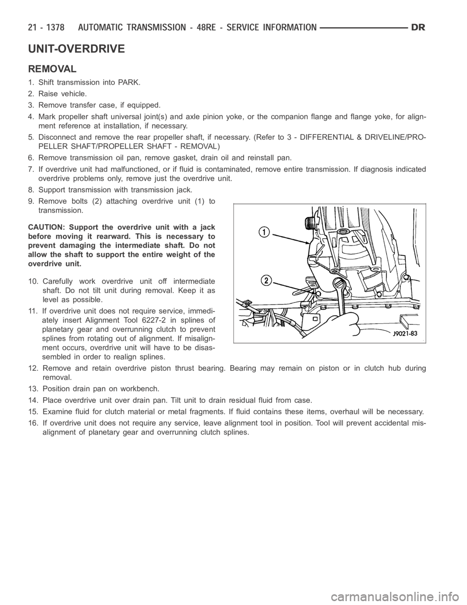
9. Remove bolts (2) attaching overdrive unit (1) to
transmission.
CAUTION: Support the overdrive unit with a jack
before moving it rearward. This is necessary to
prevent damaging the intermediate shaft. Do not
allow the shaft to support the entire weight of the
overdrive unit.
10. Carefully work overdrive unit off intermediate
shaft. Do not tilt unit during removal. Keep it as
level as possible.
11. If overdrive unit does not require service, immedi-
ately insert Alignment Tool 6227-2 in splines of
planetary gear and overrunning clutch to prevent
splines from rotating out of alignment. If misalign-
ment occurs, overdrive unit will have to be disas-
sembled in order to realign splines.
12. Remove and retain overdrive piston thrust bearing. Bearing may remainon piston or in clutch hub during
removal.
13. Position drain pan on workbench.
14. Place overdrive unit over drain pan. Tilt unit to drain residual fluid from case.
15. Examine fluid for clutch material or metal fragments. If fluid contains these items, overhaul will be necessary.
16. If overdrive unit does not require any service, leave alignment tool inposition. Tool will prevent accidental mis-
alignment of planetary gear and overrunning clutch splines.
Page 3910 of 5267
CLEANING
Clean the geartrain and case components with solvent. Dry all parts exceptthebearingswithcompressedair.Allow
bearings to air dry.
Do not use shop towels for wiping parts dry unless the towels are made from a lint-free material. A sufficient quan-
tity of lint (from shop towels, cloths, rags, etc.) could plug the transmission filter and fluid passages.
Discard the old case gasket and seals.Do not attempt to salvage these parts. They are not reusable. Replace any
of the overdrive unit snap-rings if distorted or damaged.
Minor nicks or scratches on components can be smoothed with crocus cloth. However, do not attempt to reduce
severescoringonanycomponentswithabrasive materials. Replace severely scored components; do not try to
salvage them.
INSPECTION
Check condition of the park lock components and the overdrive case.
Check the bushings in the overdrive case. Replace the bushings if severelyscored or worn. Also replace the case
seal if loose, distorted, or damaged.
Examine the overdrive and direct clutch discs and plates. Replace the discs if the facing is worn, severely scored,
or burned and flaking off. Replace the clutch plates if worn, heavily scored, or cracked. Check the lugs on the clutch
plates for wear. The plates should slide freely in the drum. Replace the plates or drum if binding occurs.
Check condition of the annulus gear, direct clutch hub, clutch drum and clutch spring. Replace the gear, hub and
drum if worn or damaged. Replace the spring if collapsed, distorted, or cracked.
Be sure the splines and lugs on the gear, drum and hub are in good condition. The clutch plates and discs should
slide freely in these components.
Inspect the thrust bearings and spring plate. Replace the plate if worn or scored. Replace the bearings if rough,
noisy, brinnelled, or worn.
Inspect the planetary gear assembly and the sun gear and bushings. If either the sun gear or the bushings are
damaged, replace the gear and bushings as an assembly. The gear and bushings are not serviced separately.
The planetary carrier and pinions must be in good condition. Also be sure the pinion pins are secure and in good
condition. Replace the carrier if worn or damaged.
Inspect the overrunning clutch and race. The race surface should be smoothand free of scores. Replace the over-
running clutch assembly or the race if either assembly is worn or damaged inany way.
Replace the shaft pilot bushing and inner bushing if damaged. Replace either shaft bearing if rough or noisy.
Replace the bearing snap-rings if distorted or cracked.
Check the machined surfaces on the output shaft. These surfaces should clean and smooth. Very minor nicks or
scratches can be smoothed with crocus cloth. Replace the shaft if worn, scored or damaged in any way.
Inspect the output shaft bushings. The small bushing is the intermediate shaft pilot bushing. The large bushing is the
overrunning clutch hub bushing. Replace either bushing if scored, pitted, cracked, or worn.
Page 3911 of 5267
ASSEMBLY
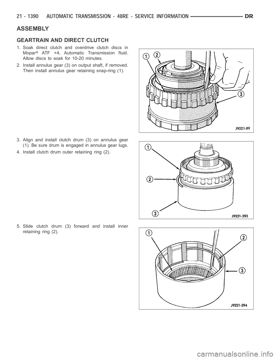
GEARTRAIN AND DIRECT CLUTCH
1. Soak direct clutch and overdrive clutch discs in
Mopar
ATF +4, Automatic Transmission fluid.
Allow discs to soak for 10-20 minutes.
2. Install annulus gear (3) on output shaft, if removed.
Then install annulus gear retaining snap-ring (1).
3. Align and install clutch drum (3) on annulus gear
(1). Be sure drum is engaged in annulus gear lugs.
4. Install clutch drum outer retaining ring (2).
5. Slide clutch drum (3) forward and install inner
retaining ring (2).
Page 3931 of 5267
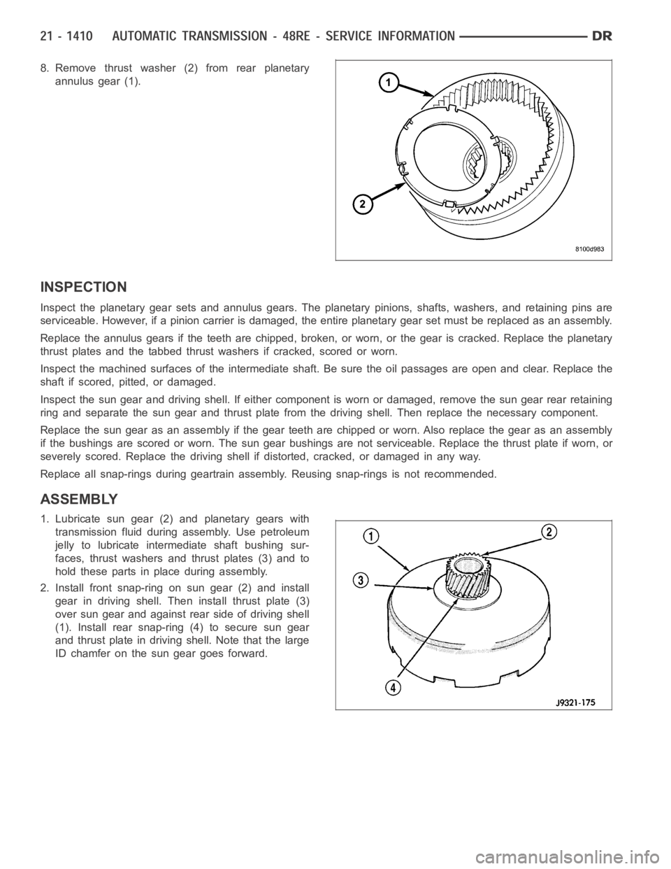
8. Remove thrust washer (2) from rear planetary
annulus gear (1).
INSPECTION
Inspect the planetary gear sets and annulus gears. The planetary pinions,shafts, washers, and retaining pins are
serviceable. However, if a pinion carrier is damaged, the entire planetarygearsetmustbereplacedasanassembly.
Replace the annulus gears if the teeth are chipped, broken, or worn, or the gear is cracked. Replace the planetary
thrust plates and the tabbed thrust washers if cracked, scored or worn.
Inspect the machined surfaces of the intermediate shaft. Be sure the oil passages are open and clear. Replace the
shaft if scored, pitted, or damaged.
Inspect the sun gear and driving shell. If either component is worn or damaged, remove the sun gear rear retaining
ring and separate the sun gear and thrust plate from the driving shell. Thenreplace the necessary component.
Replace the sun gear as an assembly if the gear teeth are chipped or worn. Also replace the gear as an assembly
if the bushings are scored or worn. The sun gear bushings are not serviceable. Replace the thrust plate if worn, or
severely scored. Replace the driving shell if distorted, cracked, or damaged in any way.
Replace all snap-rings during geartrain assembly. Reusing snap-rings isnot recommended.
ASSEMBLY
1. Lubricate sun gear (2) and planetary gears with
transmission fluid during assembly. Use petroleum
jelly to lubricate intermediate shaft bushing sur-
faces, thrust washers and thrust plates (3) and to
hold these parts in place during assembly.
2. Install front snap-ring on sun gear (2) and install
gear in driving shell. Then install thrust plate (3)
over sun gear and against rear side of driving shell
(1). Install rear snap-ring (4) to secure sun gear
and thrust plate in driving shell. Note that the large
ID chamfer on the sun gear goes forward.
Page 3933 of 5267
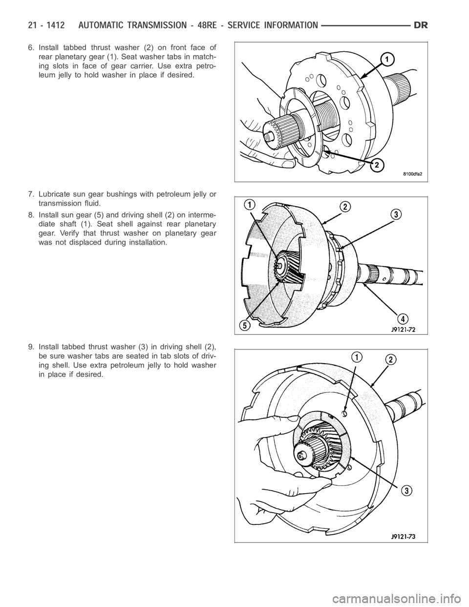
6. Install tabbed thrust washer (2) on front face of
rear planetary gear (1). Seat washer tabs in match-
ing slots in face of gear carrier. Use extra petro-
leum jelly to hold washer in place if desired.
7. Lubricate sun gear bushings with petroleum jelly or
transmission fluid.
8. Install sun gear (5) and driving shell (2) on interme-
diate shaft (1). Seat shell against rear planetary
gear. Verify that thrust washer on planetary gear
was not displaced during installation.
9. Install tabbed thrust washer (3) in driving shell (2),
be sure washer tabs are seated in tab slots of driv-
ing shell. Use extra petroleum jelly to hold washer
in place if desired.