2006 DODGE RAM SRT-10 Compression
[x] Cancel search: CompressionPage 610 of 5267

P0305-CYLINDER # 5 MISFIRE
For a complete wiring diagramRefer to Section 8W.
When Monitored:
While the engine is idling at operating temperature.
Set Condition:
Misfire detected on this cylinder.
Possible Causes
LOW FUEL
OTHER DTC’S
DAMAGED FUEL LINE
VA LV E T R A I N
OBSTRUCTED FUEL INJECTOR SUPPLY LINE
DAMAGED OR OBSTRUCTED HIGH PRESSURE CONNECTOR
EXTERNAL DAMAGED FUEL INJECTOR
INTERNAL DAMAGED FUEL INJECTOR
NO COMPRESSION
EXCESSIVE ENGINE LEAK DOWN
Always perform the Pre-Diagnostic Troubleshooting procedure before proceeding. (Refer to 9 - ENGINE -
DIAGNOSIS AND TESTING)
Diagnostic Test
1.LOW FUEL
Using the scan tool, verify that the fuel level is above 15%.
Is the fuel level above 15%?
Ye s>>
Go To 2
No>>
Addfuelgotostep2.
Perform POWERTRAIN VERIFICATION TEST VER - 1 (DIESEL). (Refer to 8 - ELECTRICAL/ELEC-
TRONIC CONTROL MODULES/ENGINE CONTROL MODULE - DIAGNOSIS AND TESTING)
2.OTHER DTC’S
Read the Freeze frame data.
Is the DTC equal to the freeze frame DTC?
Ye s>>
Go To 3
No>>
Repair any other DTC’s first.
Perform POWERTRAIN VERIFICATION TEST VER - 1 (DIESEL). (Refer to 8 - ELECTRICAL/ELEC-
TRONIC CONTROL MODULES/ENGINE CONTROL MODULE - DIAGNOSIS AND TESTING)
Page 612 of 5267

8.INTERNAL DAMAGED FUEL INJECTOR
With the scan tool, erase DTCs.
Switch the misfiring injector & high pressure connector with an injector &high pressure connector from a cylinder
that is firing properly.
Operate the vehicle.
Did the misfire DTC follow the suspect injector & high pressure connector?
Ye s>>
Replace the internal damaged fuel injector and high pressure connector.
Perform POWERTRAIN VERIFICATION TEST VER - 1 (DIESEL). (Refer to 8 - ELECTRICAL/ELEC-
TRONIC CONTROL MODULES/ENGINE CONTROL MODULE - DIAGNOSIS AND TESTING)
No>>
Go To 9
9.INTERNAL ENGINE DAMAGE
Perform engine compression test
Did the suspect cylinders pass the compression test?
Ye s>>
Go To 10
No>>
Repair the internal damage to the engine.
Perform POWERTRAIN VERIFICATION TEST VER - 1 (DIESEL). (Refer to 8 - ELECTRICAL/ELEC-
TRONIC CONTROL MODULES/ENGINE CONTROL MODULE - DIAGNOSIS AND TESTING)
10.INTERNAL ENGINE DAMAGE
Perform engine leak down test
Did the suspect cylinders pass the leak down test?
Ye s>>
Te s t C o m p l e t e .
No>>
Repair the internal damage to the engine.
Perform POWERTRAIN VERIFICATION TEST VER - 1 (DIESEL). (Refer to 8 - ELECTRICAL/ELEC-
TRONIC CONTROL MODULES/ENGINE CONTROL MODULE - DIAGNOSIS AND TESTING)
Page 613 of 5267

P0306-CYLINDER # 6 MISFIRE
For a complete wiring diagramRefer to Section 8W.
When Monitored:
While the engine is idling at operating temperature.
Set Condition:
Misfire detected on this cylinder.
Possible Causes
LOW FUEL
OTHER DTC’S
DAMAGED FUEL LINE
VA LV E T R A I N
OBSTRUCTED FUEL INJECTOR SUPPLY LINE
DAMAGED OR OBSTRUCTED HIGH PRESSURE CONNECTOR
EXTERNAL DAMAGED FUEL INJECTOR
INTERNAL DAMAGED FUEL INJECTOR
NO COMPRESSION
EXCESSIVE ENGINE LEAK DOWN
Always perform the Pre-Diagnostic Troubleshooting procedure before proceeding. (Refer to 9 - ENGINE -
DIAGNOSIS AND TESTING)
Diagnostic Test
1.LOW FUEL
Using the scan tool, verify that the fuel level is above 15%.
Is the fuel level above 15%?
Ye s>>
Go To 2
No>>
Addfuelgotostep2.
Perform POWERTRAIN VERIFICATION TEST VER - 1 (DIESEL). (Refer to 8 - ELECTRICAL/ELEC-
TRONIC CONTROL MODULES/ENGINE CONTROL MODULE - DIAGNOSIS AND TESTING)
2.OTHER DTC’S
Read the Freeze frame data.
Is the DTC equal to the freeze frame DTC?
Ye s>>
Go To 3
No>>
Repair any other DTC’s first.
Perform POWERTRAIN VERIFICATION TEST VER - 1 (DIESEL). (Refer to 8 - ELECTRICAL/ELEC-
TRONIC CONTROL MODULES/ENGINE CONTROL MODULE - DIAGNOSIS AND TESTING)
Page 615 of 5267

8.INTERNAL DAMAGED FUEL INJECTOR
With the scan tool, erase DTCs.
Switch the misfiring injector & high pressure connector with an injector &high pressure connector from a cylinder
that is firing properly.
Operate the vehicle.
Did the misfire DTC follow the suspect injectors & high pressure connectors?
Ye s>>
Replace the internal damaged fuel injector and high pressure connector.
Perform POWERTRAIN VERIFICATION TEST VER - 1 (DIESEL). (Refer to 8 - ELECTRICAL/ELEC-
TRONIC CONTROL MODULES/ENGINE CONTROL MODULE - DIAGNOSIS AND TESTING)
No>>
Go To 9
9.INTERNAL ENGINE DAMAGE
Perform engine compression test
Did the suspect cylinders pass the compression test?
Ye s>>
Go To 10
No>>
Repair the internal damage to the engine.
Perform POWERTRAIN VERIFICATION TEST VER - 1 (DIESEL). (Refer to 8 - ELECTRICAL/ELEC-
TRONIC CONTROL MODULES/ENGINE CONTROL MODULE - DIAGNOSIS AND TESTING)
10.INTERNAL ENGINE DAMAGE
Perform engine leak down test
Did the suspect cylinders pass the leak down test?
Ye s>>
Te s t C o m p l e t e .
No>>
Repair the internal damage to the engine.
Perform POWERTRAIN VERIFICATION TEST VER - 1 (DIESEL). (Refer to 8 - ELECTRICAL/ELEC-
TRONIC CONTROL MODULES/ENGINE CONTROL MODULE - DIAGNOSIS AND TESTING)
Page 1058 of 5267

12.ENGINE MECHANICAL PROBLEM
Check for any of the following conditions/mechanical problems.
AIR INDUCTION SYSTEM - must be free from leaks.
ENGINE VACUUM - must be at least 13 inches in neutral
ENGINE VALVE TIMING - must be within specifications
ENGINE COMPRESSION - must be within specifications
ENGINE EXHAUST SYSTEM - must be free of any restrictions or leaks.
ENGINE PCV SYSTEM - must flow freely
TORQUE CONVERTER STALL SPEED - must be within specifications
POWER BRAKE BOOSTER - no internal vacuum leaks
FUEL - must be free of contamination
FUEL INJECTOR - plugged or restricted injector; control wire not connectedtocorrectinjector
Are there any engine mechanical problems?
Ye s>>
Repair as necessary.
Perform the POWERTRAIN VERIFICATION TEST. (Refer to 9 - ENGINE - STANDARD PROCEDURE)
No>>
Refer to the INTERMITTENT CONDITIONSymptom (Diagnostic Procedure).
Perform the POWERTRAIN VERIFICATION TEST. (Refer to 9 - ENGINE - STANDARD PROCEDURE)
13.O2 SENSOR
NOTE: Wait a minimum of 10 minutes to allow the O2 Sensor to cool down before continuing the test.
Ignition on, engine not running.
Disconnect the harness connector(s) of the O2 Sensor(s) that had a voltagereading below 4.5 volts in the previous
step.
With the scan tool, monitor the O2 Sensor voltage reading(s).
Is the voltage above 4.5 volts for any of the O2 Sensors?
Ye s>>
Replace the O2 Sensor that had a voltage reading above 4.5 volts.
Perform the POWERTRAIN VERIFICATION TEST. (Refer to 9 - ENGINE - STANDARD PROCEDURE)
No>>
Go To 14
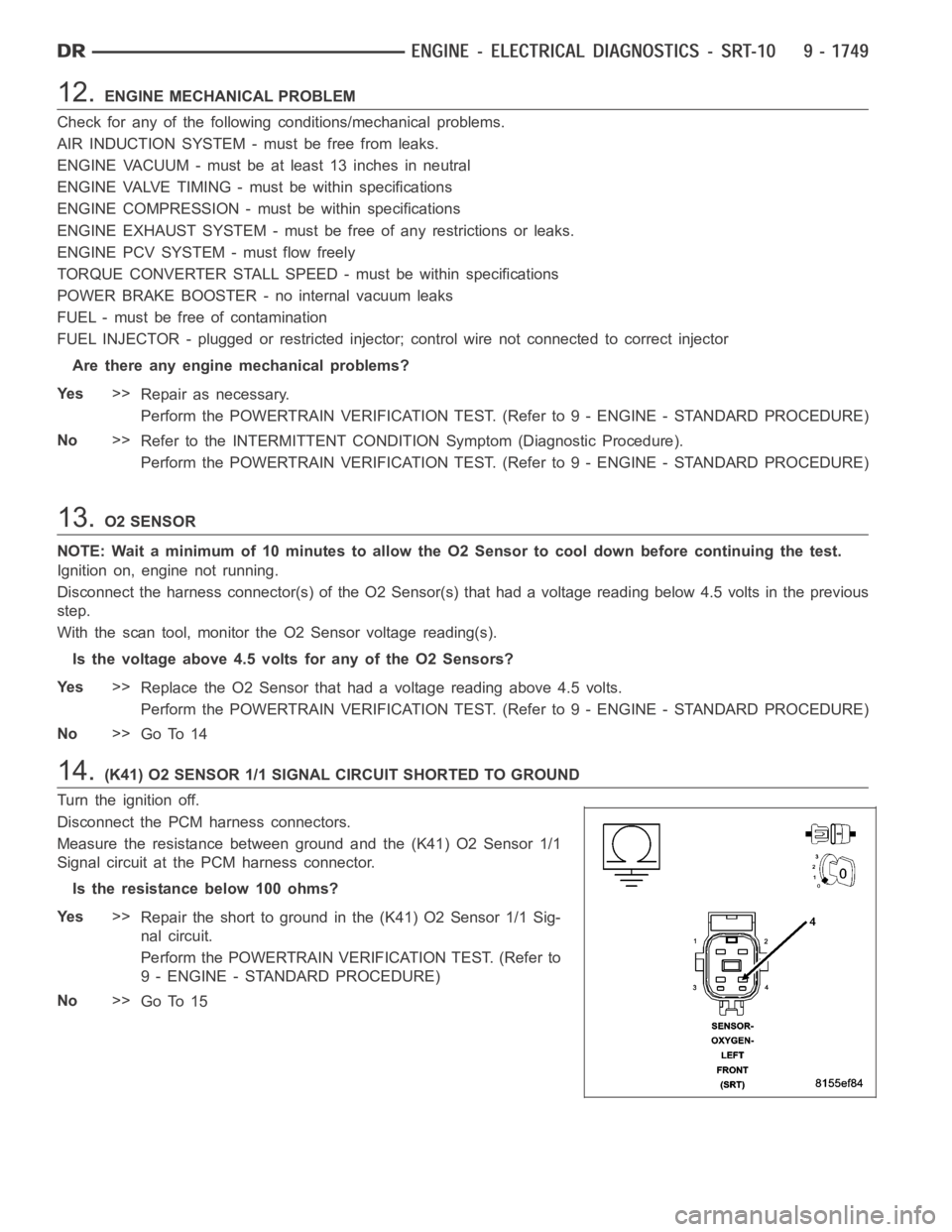
14.(K41) O2 SENSOR 1/1 SIGNAL CIRCUIT SHORTED TO GROUND
Turn the ignition off.
Disconnect the PCM harness connectors.
Measure the resistance between ground and the (K41) O2 Sensor 1/1
Signal circuit at the PCM harness connector.
Istheresistancebelow100ohms?
Ye s>>
Repair the short to ground in the (K41) O2 Sensor 1/1 Sig-
nal circuit.
Perform the POWERTRAIN VERIFICATION TEST. (Refer to
9 - ENGINE - STANDARD PROCEDURE)
No>>
Go To 15
Page 1064 of 5267

9.ECT SENSOR OPERATION
NOTE: For this test to be valid, the thermostat must be operating correctly.
NOTE: This test works best if performed on a cold engine (cold soak)
Ignition on, engine not running.
With the scan tool, read the Engine Coolant Temperature Sensor value. If theenginewasallowedtositovernight
(cold soak), the temperature value should be a sensible value that is somewhere close to the ambient temperature.
NOTE: If engine coolant temperature is above 82°C (180°F), allow the engine to cool until 65°C (150°F) is
reached.
Start the Engine.
During engine warm-up, monitor the Engine Coolant Temperature value. Thetemp value change should be a
smooth transition from start up to normal operating temp 82°C (180°F). Thevalue should reach at least 82°C
(180°F).
Did the Engine Coolant Temperature value increase smoothly and reach at least 82°C?
Ye s>>
Go To 10
No>>
Replace the Engine Coolant Temperature Sensor.
Perform the POWERTRAIN VERIFICATION TEST. (Refer to 9 - ENGINE - STANDARD PROCEDURE)
10.ENGINE MECHANICAL PROBLEM
Check for any of the following conditions/mechanical problems.
AIR INDUCTION SYSTEM - must be free from restrictions.
ENGINE VACUUM - must be at least 13 inches in neutral
ENGINE VALVE TIMING - must be within specifications
ENGINE COMPRESSION - must be within specifications
ENGINE EXHAUST SYSTEM - must be free of any restrictions or leaks.
ENGINE PCV SYSTEM - must flow freely
TORQUE CONVERTER STALL SPEED - must be within specifications
POWER BRAKE BOOSTER - no internal vacuum leaks
FUEL - must be free of contamination
FUEL INJECTOR - plugged or restricted injector; control wire not connectedtocorrectinjector
Are there any engine mechanical problems?
Ye s>>
Repair as necessary.
Perform the POWERTRAIN VERIFICATION TEST. (Refer to 9 - ENGINE - STANDARD PROCEDURE)
No>>
Refer to the INTERMITTENT CONDITION Diagnostic Procedure.
Perform the POWERTRAIN VERIFICATION TEST. (Refer to 9 - ENGINE - STANDARD PROCEDURE)
11 .O2 SENSOR
Disconnect the sensor harness connector of the O2 Sensor(s) that had a voltage value greater than 4.5 volts in the
previous step.
Ignition on, engine not running.
With the scan tool, monitor the O2 Sensor voltage reading(s).
Is the O2 Sensor voltage above 4.5 volts?
Ye s>>
Replace the O2 Sensor.
Perform the POWERTRAIN VERIFICATION TEST. (Refer to 9 - ENGINE - STANDARD PROCEDURE)
No>>
Go To 12
Page 1071 of 5267

12.ENGINE MECHANICAL PROBLEM
Check for any of the following conditions/mechanical problems.
AIR INDUCTION SYSTEM - must be free from leaks.
ENGINE VACUUM - must be at least 13 inches in neutral
ENGINE VALVE TIMING - must be within specifications
ENGINE COMPRESSION - must be within specifications
ENGINE EXHAUST SYSTEM - must be free of any restrictions or leaks.
ENGINE PCV SYSTEM - must flow freely
TORQUE CONVERTER STALL SPEED - must be within specifications
POWER BRAKE BOOSTER - no internal vacuum leaks
FUEL - must be free of contamination
FUEL INJECTOR - plugged or restricted injector; control wire not connectedtocorrectinjector
Are there any engine mechanical problems?
Ye s>>
Repair as necessary.
Perform the POWERTRAIN VERIFICATION TEST. (Refer to 9 - ENGINE - STANDARD PROCEDURE)
No>>
Refer to the INTERMITTENT CONDITIONSymptom (Diagnostic Procedure).
Perform the POWERTRAIN VERIFICATION TEST. (Refer to 9 - ENGINE - STANDARD PROCEDURE)
13.O2 SENSOR
NOTE: Wait a minimum of 10 minutes to allow the O2 Sensor to cool down before continuing the test.
Ignition on, engine not running.
Disconnect the harness connector(s) of the O2 Sensor(s) that had a voltagereading below 4.5 volts in the previous
step.
With the scan tool, monitor the O2 Sensor voltage reading(s).
Is the voltage above 4.5 volts for any of the O2 Sensors?
Ye s>>
Replace the O2 Sensor that had a voltage reading above 4.5 volts.
Perform the POWERTRAIN VERIFICATION TEST. (Refer to 9 - ENGINE - STANDARD PROCEDURE)
No>>
Go To 14
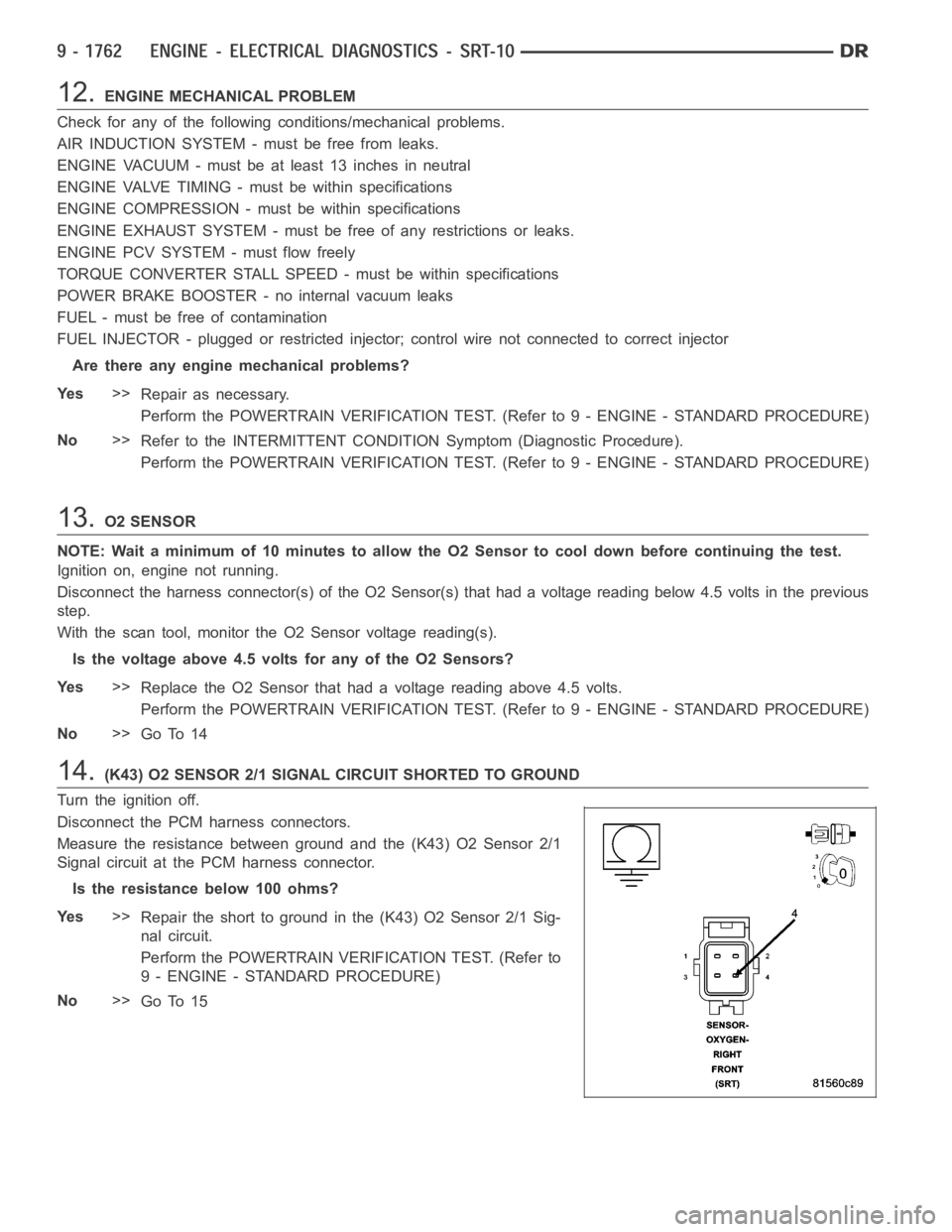
14.(K43) O2 SENSOR 2/1 SIGNAL CIRCUIT SHORTED TO GROUND
Turn the ignition off.
Disconnect the PCM harness connectors.
Measure the resistance between ground and the (K43) O2 Sensor 2/1
Signal circuit at the PCM harness connector.
Istheresistancebelow100ohms?
Ye s>>
Repair the short to ground in the (K43) O2 Sensor 2/1 Sig-
nal circuit.
Perform the POWERTRAIN VERIFICATION TEST. (Refer to
9 - ENGINE - STANDARD PROCEDURE)
No>>
Go To 15
Page 1077 of 5267

9.ECT SENSOR OPERATION
NOTE: For this test to be valid, the thermostat must be operating correctly.
NOTE: This test works best if performed on a cold engine (cold soak)
Ignition on, engine not running.
With the scan tool, read the Engine Coolant Temperature Sensor value. If theenginewasallowedtositovernight
(cold soak), the temperature value should be a sensible value that is somewhere close to the ambient temperature.
NOTE: If engine coolant temperature is above 82°C (180°F), allow the engine to cool until 65°C (150°F) is
reached.
Start the Engine.
During engine warm-up, monitor the Engine Coolant Temperature value. Thetemp value change should be a
smooth transition from start up to normal operating temp 82°C (180°F). Thevalue should reach at least 82°C
(180°F).
Did the Engine Coolant Temperature value increase smoothly and reach at least 82°C?
Ye s>>
Go To 10
No>>
Replace the Engine Coolant Temperature Sensor.
Perform the POWERTRAIN VERIFICATION TEST. (Refer to 9 - ENGINE - STANDARD PROCEDURE)
10.ENGINE MECHANICAL PROBLEM
Check for any of the following conditions/mechanical problems.
AIR INDUCTION SYSTEM - must be free from restrictions.
ENGINE VACUUM - must be at least 13 inches in neutral
ENGINE VALVE TIMING - must be within specifications
ENGINE COMPRESSION - must be within specifications
ENGINE EXHAUST SYSTEM - must be free of any restrictions or leaks.
ENGINE PCV SYSTEM - must flow freely
TORQUE CONVERTER STALL SPEED - must be within specifications
POWER BRAKE BOOSTER - no internal vacuum leaks
FUEL - must be free of contamination
FUEL INJECTOR - plugged or restricted injector; control wire not connectedtocorrectinjector
Are there any engine mechanical problems?
Ye s>>
Repair as necessary.
Perform the POWERTRAIN VERIFICATION TEST. (Refer to 9 - ENGINE - STANDARD PROCEDURE)
No>>
Refer to the INTERMITTENT CONDITION Diagnostic Procedure.
Perform the POWERTRAIN VERIFICATION TEST. (Refer to 9 - ENGINE - STANDARD PROCEDURE)
11 .O2 SENSOR
Disconnect the sensor harness connector of the O2 Sensor(s) that had a voltage value greater than 4.5 volts in the
previous step.
Ignition on, engine not running.
With the scan tool, monitor the O2 Sensor voltage reading(s).
Is the O2 Sensor voltage above 4.5 volts?
Ye s>>
Replace the O2 Sensor.
Perform the POWERTRAIN VERIFICATION TEST. (Refer to 9 - ENGINE - STANDARD PROCEDURE)
No>>
Go To 12