2006 DODGE RAM SRT-10 compression ratio
[x] Cancel search: compression ratioPage 1172 of 5267
8.FUEL INJECTOR OPERATION
WARNING: The fuel system is under a constant pressure (even with the engineoff). Before testing or ser-
vicing any fuel system hose, fitting or line, the fuel system pressure mustbe released. Failure to follow
these instructions can result in personal injury or death.
CAUTION: After each Fuel Injector actuation, start the engine to clean thecylinder of fuel. Failure to do so
could cause engine damage.
Remove special tool #C4390.
Start the engine and allow the fuel pressure to reach maximum pressure.
Ignition on, engine not running.
Using the scan tool, actuate the Fuel Injector.
Monitor the fuel pressure gauge.
Does the fuel pressure gauge indicate a drop in fuel pressure?
Ye s>>
Go To 9
No>>
Go To 10
NOTE: Turn the ignition off, remove the Fuel Pressure gauge, and connect the fuel lines before continuing.
9.ENGINE MECHANICAL
Check for any of the following conditions/mechanical problems.
ENGINE VACUUM - must be at least 13 inches in neutral
ENGINE VALVE TIMING - must be within specifications
ENGINE COMPRESSION - must be within specifications
ENGINE EXHAUST SYSTEM - must be free of any restrictions or leaks.
ENGINE PCV SYSTEM - must flow freely
TORQUE CONVERTER STALL SPEED - must be within specifications
POWER BRAKE BOOSTER - no internal vacuum leaks
FUEL - must be free of contamination
CAM LOBES - must not be worn excessively
CYLINDER LEAKAGE TEST - must be within specifications
VALVE SPRINGS - cannot be weak or broken
Are there any engine mechanical problems?
Ye s>>
Repair as necessary.
Perform the POWERTRAIN VERIFICATION TEST. (Refer to 9 - ENGINE - STANDARD PROCEDURE)
No>>
Go To 17
Page 1181 of 5267
NOTE: The pressure should not fall below 241 KPa (35 psi).
Does the pressure fall below the listed specification?
Ye s>>
Replace the leaking Fuel Injector(s).
Perform the POWERTRAIN VERIFICATION TEST. (Refer to 9 - ENGINE - STANDARD PROCEDURE)
No>>
Go To 8
8.FUEL INJECTOR OPERATION
WARNING: The fuel system is under a constant pressure (even with the engineoff). Before testing or ser-
vicing any fuel system hose, fitting or line, the fuel system pressure mustbe released. Failure to follow
these instructions can result in personal injury or death.
CAUTION: After each Fuel Injector actuation, start the engine to clean thecylinder of fuel. Failure to do so
could cause engine damage.
Remove special tool #C4390.
Start the engine and allow the fuel pressure to reach maximum pressure.
Ignition on, engine not running.
Using the scan tool, actuate the Fuel Injector.
Monitor the fuel pressure gauge.
Does the fuel pressure gauge indicate a drop in fuel pressure?
Ye s>>
Go To 9
No>>
Go To 10
NOTE: Turn the ignition off, remove the Fuel Pressure gauge, and connect the fuel lines before continuing.
9.ENGINE MECHANICAL
Check for any of the following conditions/mechanical problems.
ENGINE VACUUM - must be at least 13 inches in neutral
ENGINE VALVE TIMING - must be within specifications
ENGINE COMPRESSION - must be within specifications
ENGINE EXHAUST SYSTEM - must be free of any restrictions or leaks.
ENGINE PCV SYSTEM - must flow freely
TORQUE CONVERTER STALL SPEED - must be within specifications
POWER BRAKE BOOSTER - no internal vacuum leaks
FUEL - must be free of contamination
CAM LOBES - must not be worn excessively
CYLINDER LEAKAGE TEST - must be within specifications
VALVE SPRINGS - cannot be weak or broken
Are there any engine mechanical problems?
Ye s>>
Repair as necessary.
Perform the POWERTRAIN VERIFICATION TEST. (Refer to 9 - ENGINE - STANDARD PROCEDURE)
No>>
Go To 17
Page 1190 of 5267
NOTE: The pressure should not fall below 241 KPa (35 psi).
Does the pressure fall below the listed specification?
Ye s>>
Replace the leaking Fuel Injector(s).
Perform the POWERTRAIN VERIFICATION TEST. (Refer to 9 - ENGINE - STANDARD PROCEDURE)
No>>
Go To 8
8.FUEL INJECTOR OPERATION
WARNING: The fuel system is under a constant pressure (even with the engineoff). Before testing or ser-
vicing any fuel system hose, fitting or line, the fuel system pressure mustbe released. Failure to follow
these instructions can result in personal injury or death.
CAUTION: After each Fuel Injector actuation, start the engine to clean thecylinder of fuel. Failure to do so
could cause engine damage.
Remove special tool #C4390.
Start the engine and allow the fuel pressure to reach maximum pressure.
Ignition on, engine not running.
Using the scan tool, actuate the Fuel Injector.
Monitor the fuel pressure gauge.
Does the fuel pressure gauge indicate a drop in fuel pressure?
Ye s>>
Go To 9
No>>
Go To 10
NOTE: Turn the ignition off, remove the Fuel Pressure gauge, and connect the fuel lines before continuing.
9.ENGINE MECHANICAL
Check for any of the following conditions/mechanical problems.
ENGINE VACUUM - must be at least 13 inches in neutral
ENGINE VALVE TIMING - must be within specifications
ENGINE COMPRESSION - must be within specifications
ENGINE EXHAUST SYSTEM - must be free of any restrictions or leaks.
ENGINE PCV SYSTEM - must flow freely
TORQUE CONVERTER STALL SPEED - must be within specifications
POWER BRAKE BOOSTER - no internal vacuum leaks
FUEL - must be free of contamination
CAM LOBES - must not be worn excessively
CYLINDER LEAKAGE TEST - must be within specifications
VALVE SPRINGS - cannot be weak or broken
Are there any engine mechanical problems?
Ye s>>
Repair as necessary.
Perform the POWERTRAIN VERIFICATION TEST. (Refer to 9 - ENGINE - STANDARD PROCEDURE)
No>>
Go To 17
Page 1199 of 5267
NOTE: The pressure should not fall below 241 KPa (35 psi).
Does the pressure fall below the listed specification?
Ye s>>
Replace the leaking Fuel Injector(s).
Perform the POWERTRAIN VERIFICATION TEST. (Refer to 9 - ENGINE - STANDARD PROCEDURE)
No>>
Go To 8
8.FUEL INJECTOR OPERATION
WARNING: The fuel system is under a constant pressure (even with the engineoff). Before testing or ser-
vicing any fuel system hose, fitting or line, the fuel system pressure mustbe released. Failure to follow
these instructions can result in personal injury or death.
CAUTION: After each Fuel Injector actuation, start the engine to clean thecylinder of fuel. Failure to do so
could cause engine damage.
Remove special tool #C4390.
Start the engine and allow the fuel pressure to reach maximum pressure.
Ignition on, engine not running.
Using the scan tool, actuate the Fuel Injector.
Monitor the fuel pressure gauge.
Does the fuel pressure gauge indicate a drop in fuel pressure?
Ye s>>
Go To 9
No>>
Go To 10
NOTE: Turn the ignition off, remove the Fuel Pressure gauge, and connect the fuel lines before continuing.
9.ENGINE MECHANICAL
Check for any of the following conditions/mechanical problems.
ENGINE VACUUM - must be at least 13 inches in neutral
ENGINE VALVE TIMING - must be within specifications
ENGINE COMPRESSION - must be within specifications
ENGINE EXHAUST SYSTEM - must be free of any restrictions or leaks.
ENGINE PCV SYSTEM - must flow freely
TORQUE CONVERTER STALL SPEED - must be within specifications
POWER BRAKE BOOSTER - no internal vacuum leaks
FUEL - must be free of contamination
CAM LOBES - must not be worn excessively
CYLINDER LEAKAGE TEST - must be within specifications
VALVE SPRINGS - cannot be weak or broken
Are there any engine mechanical problems?
Ye s>>
Repair as necessary.
Perform the POWERTRAIN VERIFICATION TEST. (Refer to 9 - ENGINE - STANDARD PROCEDURE)
No>>
Go To 17
Page 1208 of 5267
NOTE: The pressure should not fall below 241 KPa (35 psi).
Does the pressure fall below the listed specification?
Ye s>>
Replace the leaking Fuel Injector(s).
Perform the POWERTRAIN VERIFICATION TEST. (Refer to 9 - ENGINE - STANDARD PROCEDURE)
No>>
Go To 8
8.FUEL INJECTOR OPERATION
WARNING: The fuel system is under a constant pressure (even with the engineoff). Before testing or ser-
vicing any fuel system hose, fitting or line, the fuel system pressure mustbe released. Failure to follow
these instructions can result in personal injury or death.
CAUTION: After each Fuel Injector actuation, start the engine to clean thecylinder of fuel. Failure to do so
could cause engine damage.
Remove special tool #C4390.
Start the engine and allow the fuel pressure to reach maximum pressure.
Ignition on, engine not running.
Using the scan tool, actuate the Fuel Injector.
Monitor the fuel pressure gauge.
Does the fuel pressure gauge indicate a drop in fuel pressure?
Ye s>>
Go To 9
No>>
Go To 10
NOTE: Turn the ignition off, remove the Fuel Pressure gauge, and connect the fuel lines before continuing.
9.ENGINE MECHANICAL
Check for any of the following conditions/mechanical problems.
ENGINE VACUUM - must be at least 13 inches in neutral
ENGINE VALVE TIMING - must be within specifications
ENGINE COMPRESSION - must be within specifications
ENGINE EXHAUST SYSTEM - must be free of any restrictions or leaks.
ENGINE PCV SYSTEM - must flow freely
TORQUE CONVERTER STALL SPEED - must be within specifications
POWER BRAKE BOOSTER - no internal vacuum leaks
FUEL - must be free of contamination
CAM LOBES - must not be worn excessively
CYLINDER LEAKAGE TEST - must be within specifications
VALVE SPRINGS - cannot be weak or broken
Are there any engine mechanical problems?
Ye s>>
Repair as necessary.
Perform the POWERTRAIN VERIFICATION TEST. (Refer to 9 - ENGINE - STANDARD PROCEDURE)
No>>
Go To 17
Page 1217 of 5267
8.FUEL INJECTOR OPERATION
WARNING: The fuel system is under a constant pressure (even with the engineoff). Before testing or ser-
vicing any fuel system hose, fitting or line, the fuel system pressure mustbe released. Failure to follow
these instructions can result in personal injury or death.
CAUTION: After each Fuel Injector actuation, start the engine to clean thecylinder of fuel. Failure to do so
could cause engine damage.
Remove special tool #C4390.
Start the engine and allow the fuel pressure to reach maximum pressure.
Ignition on, engine not running.
Using the scan tool, actuate the Fuel Injector.
Monitor the fuel pressure gauge.
Does the fuel pressure gauge indicate a drop in fuel pressure?
Ye s>>
Go To 9
No>>
Go To 10
NOTE: Turn the ignition off, remove the Fuel Pressure gauge, and connect the fuel lines before continuing.
9.ENGINE MECHANICAL
Check for any of the following conditions/mechanical problems.
ENGINE VACUUM - must be at least 13 inches in neutral
ENGINE VALVE TIMING - must be within specifications
ENGINE COMPRESSION - must be within specifications
ENGINE EXHAUST SYSTEM - must be free of any restrictions or leaks.
ENGINE PCV SYSTEM - must flow freely
TORQUE CONVERTER STALL SPEED - must be within specifications
POWER BRAKE BOOSTER - no internal vacuum leaks
FUEL - must be free of contamination
CAM LOBES - must not be worn excessively
CYLINDER LEAKAGE TEST - must be within specifications
VALVE SPRINGS - cannot be weak or broken
Are there any engine mechanical problems?
Ye s>>
Repair as necessary.
Perform the POWERTRAIN VERIFICATION TEST. (Refer to 9 - ENGINE - STANDARD PROCEDURE)
No>>
Go To 17
Page 1487 of 5267
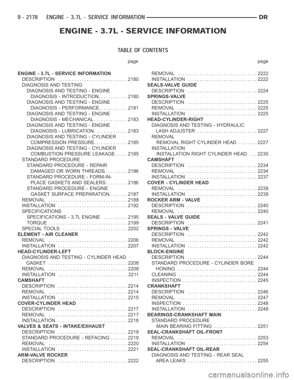
page page
ENGINE - 3.7L - SERVICE INFORMATION
DESCRIPTION ............................. 2180
DIAGNOSIS AND TESTING
DIAGNOSIS AND TESTING - ENGINE
DIAGNOSIS - INTRODUCTION............. 2180
DIAGNOSIS AND TESTING - ENGINE
DIAGNOSIS - PERFORMANCE............. 2181
DIAGNOSIS AND TESTING - ENGINE
DIAGNOSIS - MECHANICAL............... 2183
DIAGNOSIS AND TESTING - ENGINE
DIAGNOSIS - LUBRICATION............... 2183
DIAGNOSIS AND TESTING - CYLINDER
COMPRESSION PRESSURE............... 2185
DIAGNOSIS AND TESTING - CYLINDER
COMBUSTION PRESSURE LEAKAGE...... 2185
STANDARD PROCEDURE
STANDARD PROCEDURE - REPAIR
DAMAGED OR WORN THREADS.......... 2186
STANDARD PROCEDURE - FORM-IN-
PLACE GASKETS AND SEALERS.......... 2186
STANDARD PROCEDURE - ENGINE
GASKET SURFACE PREPARATION........ 2187
REMOVAL ................................. 2188
INSTALLATION ............................. 2192
SPECIFICATIONS
SPECIFICATIONS - 3.7L ENGINE .......... 2195
TORQUE ................................. 2199
SPECIAL TOOLS ........................... 2202
ELEMENT - AIR CLEANER
REMOVAL ................................. 2206
INSTALLATION ............................. 2207
HEAD-CYLINDER-LEFT
DIAGNOSIS AND TESTING - CYLINDER HEAD
GASKET . . ............................... 2208
REMOVAL ................................. 2208
INSTALLATION ............................. 2211
CAMSHAFT
DESCRIPTION ............................. 2214
REMOVAL ................................. 2214
INSTALLATION ............................. 2215
COVER-CYLINDER HEAD
DESCRIPTION ............................. 2217
REMOVAL ................................. 2217
INSTALLATION ............................. 2218
VALVES & SEATS - INTAKE/EXHAUST
DESCRIPTION ............................. 2219
STANDARD PROCEDURE - REFACING ....... 2219
REMOVAL ................................. 2220
INSTALLATION ............................. 2221
ARM-VALVE ROCKER
DESCRIPTION ............................. 2222REMOVAL ................................. 2222
INSTALLATION ............................. 2222
SEALS-VALVE GUIDE
DESCRIPTION ............................. 2224
SPRINGS-VALVE
DESCRIPTION ............................. 2225
REMOVAL ................................. 2225
INSTALLATION ............................. 2225
HEAD-CYLINDER-RIGHT
DIAGNOSIS AND TESTING - HYDRAULIC
LASH ADJUSTER ......................... 2227
REMOVAL
REMOVAL RIGHT CYLINDER HEAD ........ 2227
INSTALLATION
INSTALLATION RIGHT CYLINDER HEAD . . . 2230
CAMSHAFT
DESCRIPTION ............................. 2234
REMOVAL ................................. 2234
INSTALLATION ............................. 2237
COVER - CYLINDER HEAD
REMOVAL ................................. 2239
INSTALLATION ............................. 2239
ROCKER ARM - VALVE
DESCRIPTION ............................. 2240
REMOVAL ................................. 2240
SEALS - VALVE GUIDE
DESCRIPTION ............................. 2241
SPRINGS - VALVE
DESCRIPTION ............................. 2242
REMOVAL ................................. 2242
INSTALLATION ............................. 2242
BLOCK-ENGINE
DESCRIPTION ............................. 2244
STANDARD PROCEDURE - CYLINDER BORE
HONING ................................. 2244
CLEANING ................................. 2244
INSPECTION............................... 2245
CRANKSHAFT
DESCRIPTION ............................. 2246
REMOVAL ................................. 2247
INSPECTION............................... 2248
INSTALLATION ............................. 2248
BEARINGS-CRANKSHAFT MAIN
STANDARD PROCEDURE
MAIN BEARING FITTING.................. 2251
SEAL-CRANKSHAFT OIL-FRONT
REMOVAL ................................. 2253
INSTALLATION ............................. 2254
SEAL-CRANKSHAFT OIL-REAR
DIAGNOSIS AND TESTING - REAR SEAL
AREA LEAKS ............................. 2255
Page 1491 of 5267
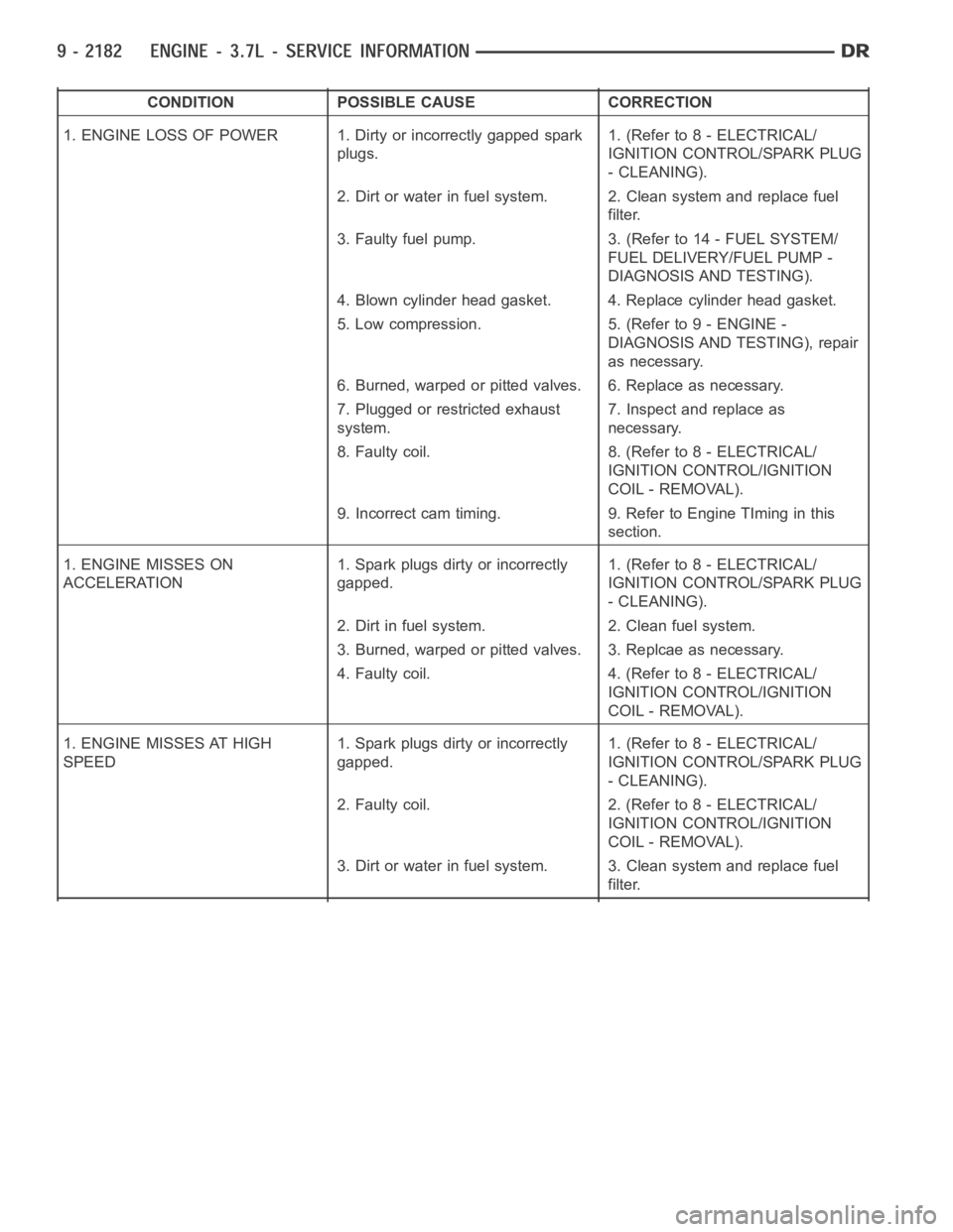
CONDITION POSSIBLE CAUSE CORRECTION
1. ENGINE LOSS OF POWER 1. Dirty or incorrectly gapped spark
plugs.1. (Refer to 8 - ELECTRICAL/
IGNITION CONTROL/SPARK PLUG
- CLEANING).
2. Dirt or water in fuel system. 2. Clean system and replace fuel
filter.
3. Faulty fuel pump. 3. (Refer to 14 - FUEL SYSTEM/
FUEL DELIVERY/FUEL PUMP -
DIAGNOSIS AND TESTING).
4. Blown cylinder head gasket. 4. Replace cylinder head gasket.
5. Low compression. 5. (Refer to 9 - ENGINE -
DIAGNOSIS AND TESTING), repair
as necessary.
6. Burned, warped or pitted valves. 6. Replace as necessary.
7. Plugged or restricted exhaust
system.7. Inspect and replace as
necessary.
8. Faulty coil. 8. (Refer to 8 - ELECTRICAL/
IGNITION CONTROL/IGNITION
COIL - REMOVAL).
9. Incorrect cam timing. 9. Refer to Engine TIming in this
section.
1. ENGINE MISSES ON
ACCELERATION1. Spark plugs dirty or incorrectly
gapped.1. (Refer to 8 - ELECTRICAL/
IGNITION CONTROL/SPARK PLUG
- CLEANING).
2. Dirt in fuel system. 2. Clean fuel system.
3. Burned, warped or pitted valves. 3. Replcae as necessary.
4. Faulty coil. 4. (Refer to 8 - ELECTRICAL/
IGNITION CONTROL/IGNITION
COIL - REMOVAL).
1. ENGINE MISSES AT HIGH
SPEED1. Spark plugs dirty or incorrectly
gapped.1. (Refer to 8 - ELECTRICAL/
IGNITION CONTROL/SPARK PLUG
- CLEANING).
2. Faulty coil. 2. (Refer to 8 - ELECTRICAL/
IGNITION CONTROL/IGNITION
COIL - REMOVAL).
3. Dirt or water in fuel system. 3. Clean system and replace fuel
filter.