2006 DODGE RAM SRT-10 compression ratio
[x] Cancel search: compression ratioPage 1504 of 5267
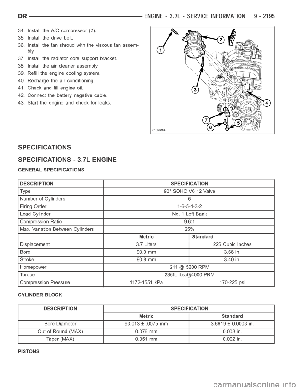
34. Install the A/C compressor (2).
35. Install the drive belt.
36. Install the fan shroud with the viscous fan assem-
bly.
37. Install the radiator core support bracket.
38. Install the air cleaner assembly.
39. Refill the engine cooling system.
40. Recharge the air conditioning.
41. Check and fill engine oil.
42. Connect the battery negative cable.
43. Start the engine and check for leaks.
SPECIFICATIONS
SPECIFICATIONS - 3.7L ENGINE
GENERAL SPECIFICATIONS
DESCRIPTION SPECIFICATION
Type 90°SOHCV612Valve
Number of Cylinders 6
Firing Order 1-6-5-4-3-2
Lead Cylinder No. 1 Left Bank
Compression Ratio 9.6:1
Max. Variation Between Cylinders 25%
Metric Standard
Displacement 3.7 Liters 226 Cubic Inches
Bore 93.0 mm 3.66 in.
Stroke 90.8 mm 3.40 in.
Horsepower 211 @ 5200 RPM
Torque 236ft. lbs.@4000 PRM
Compression Pressure 1172-1551 kPa 170-225 psi
CYLINDER BLOCK
DESCRIPTION SPECIFICATION
Metric Standard
Bore Diameter 93.013 ± .0075 mm 3.6619 ± 0.0003 in.
Out of Round (MAX) 0.076 mm 0.003 in.
Taper (MAX) 0.051 mm 0.002 in.
PISTONS
Page 1517 of 5267
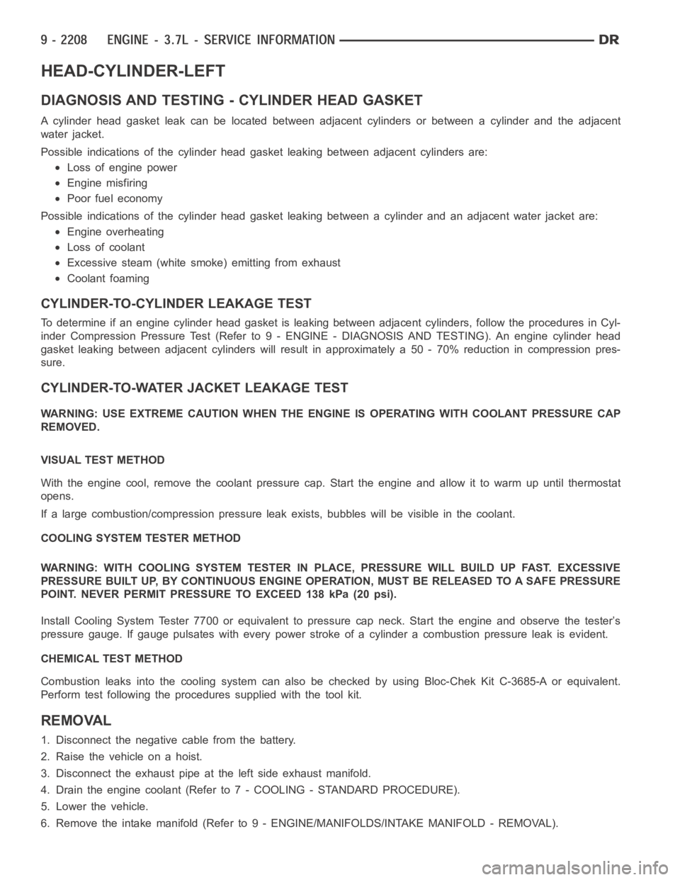
HEAD-CYLINDER-LEFT
DIAGNOSIS AND TESTING - CYLINDER HEAD GASKET
A cylinder head gasket leak can be located between adjacent cylinders or between a cylinder and the adjacent
water jacket.
Possible indications of the cylinder head gasket leaking between adjacent cylinders are:
Loss of engine power
Engine misfiring
Poor fuel economy
Possible indications of the cylinder head gasket leaking between a cylinder and an adjacent water jacket are:
Engine overheating
Loss of coolant
Excessive steam (white smoke) emitting from exhaust
Coolant foaming
CYLINDER-TO-CYLINDER LEAKAGE TEST
To determine if an engine cylinder head gasket is leaking between adjacentcylinders, follow the procedures in Cyl-
inder Compression Pressure Test (Refer to 9 - ENGINE - DIAGNOSIS AND TESTING). An engine cylinder head
gasket leaking between adjacent cylinders will result in approximately a50 - 70% reduction in compression pres-
sure.
CYLINDER-TO-WATER JACKET LEAKAGE TEST
WARNING: USE EXTREME CAUTION WHEN THE ENGINE IS OPERATING WITH COOLANT PRESSURE CAP
REMOVED.
VISUAL TEST METHOD
With the engine cool, remove the coolant pressure cap. Start the engine andallow it to warm up until thermostat
opens.
If a large combustion/compression pressure leak exists, bubbles will be visible in the coolant.
COOLING SYSTEM TESTER METHOD
WARNING: WITH COOLING SYSTEM TESTER IN PLACE, PRESSURE WILL BUILD UP FAST.EXCESSIVE
PRESSURE BUILT UP, BY CONTINUOUS ENGINE OPERATION, MUST BE RELEASED TO A SAFE PRESSURE
POINT. NEVER PERMIT PRESSURE TO EXCEED 138 kPa (20 psi).
Install Cooling System Tester 7700 or equivalent to pressure cap neck. Start the engine and observe the tester’s
pressure gauge. If gauge pulsates with every power stroke of a cylinder a combustion pressure leak is evident.
CHEMICAL TEST METHOD
Combustion leaks into the cooling system can also be checked by using Bloc-Chek Kit C-3685-A or equivalent.
Perform test following the procedures supplied with the tool kit.
REMOVAL
1. Disconnect the negative cable from the battery.
2. Raise the vehicle on a hoist.
3. Disconnect the exhaust pipe at the left side exhaust manifold.
4. Drain the engine coolant (Refer to 7 - COOLING - STANDARD PROCEDURE).
5. Lower the vehicle.
6. Remove the intake manifold (Refer to 9 - ENGINE/MANIFOLDS/INTAKE MANIFOLD - REMOVAL).
Page 1626 of 5267
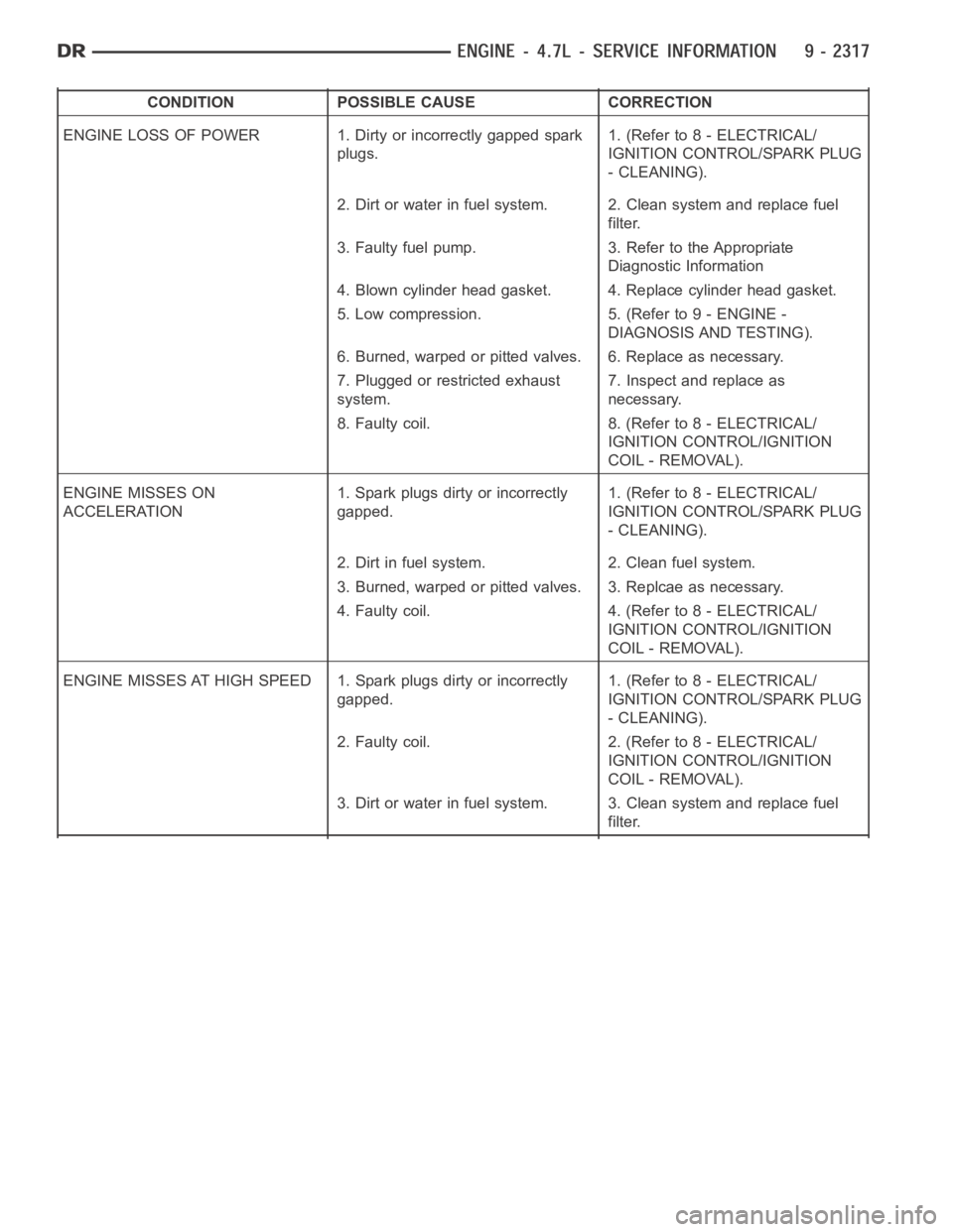
CONDITION POSSIBLE CAUSE CORRECTION
ENGINE LOSS OF POWER 1. Dirty or incorrectly gapped spark
plugs.1. (Refer to 8 - ELECTRICAL/
IGNITION CONTROL/SPARK PLUG
- CLEANING).
2. Dirt or water in fuel system. 2. Clean system and replace fuel
filter.
3. Faulty fuel pump. 3. Refer to the Appropriate
Diagnostic Information
4. Blown cylinder head gasket. 4. Replace cylinder head gasket.
5. Low compression. 5. (Refer to 9 - ENGINE -
DIAGNOSIS AND TESTING).
6. Burned, warped or pitted valves. 6. Replace as necessary.
7. Plugged or restricted exhaust
system.7. Inspect and replace as
necessary.
8. Faulty coil. 8. (Refer to 8 - ELECTRICAL/
IGNITION CONTROL/IGNITION
COIL - REMOVAL).
ENGINE MISSES ON
ACCELERATION1. Spark plugs dirty or incorrectly
gapped.1. (Refer to 8 - ELECTRICAL/
IGNITION CONTROL/SPARK PLUG
- CLEANING).
2. Dirt in fuel system. 2. Clean fuel system.
3. Burned, warped or pitted valves. 3. Replcae as necessary.
4. Faulty coil. 4. (Refer to 8 - ELECTRICAL/
IGNITION CONTROL/IGNITION
COIL - REMOVAL).
ENGINE MISSES AT HIGH SPEED 1. Spark plugs dirty or incorrectly
gapped.1. (Refer to 8 - ELECTRICAL/
IGNITION CONTROL/SPARK PLUG
- CLEANING).
2. Faulty coil. 2. (Refer to 8 - ELECTRICAL/
IGNITION CONTROL/IGNITION
COIL - REMOVAL).
3. Dirt or water in fuel system. 3. Clean system and replace fuel
filter.
Page 1629 of 5267
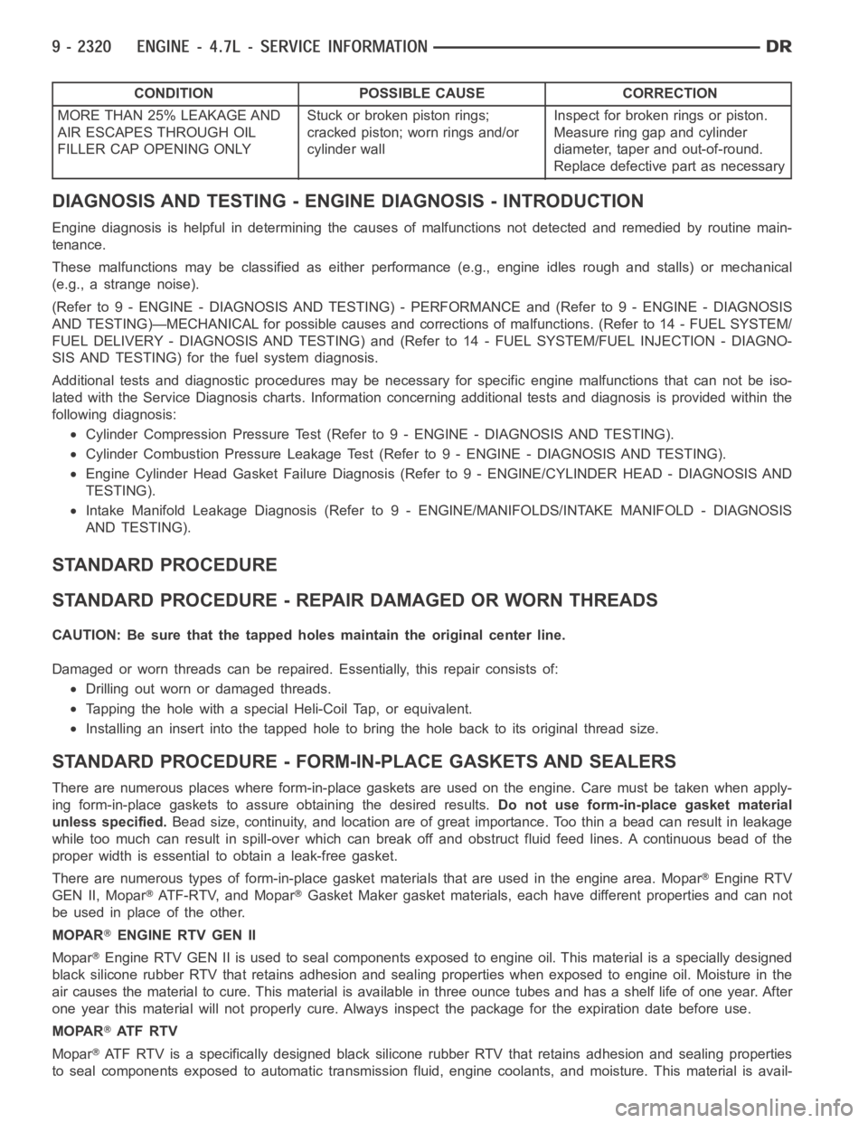
CONDITION POSSIBLE CAUSE CORRECTION
MORE THAN 25% LEAKAGE AND
AIR ESCAPES THROUGH OIL
FILLER CAP OPENING ONLYStuckorbrokenpistonrings;
cracked piston; worn rings and/or
cylinder wallInspect for broken rings or piston.
Measure ring gap and cylinder
diameter, taper and out-of-round.
Replace defective part as necessary
DIAGNOSIS AND TESTING - ENGINE DIAGNOSIS - INTRODUCTION
Engine diagnosis is helpful in determining the causes of malfunctions notdetected and remedied by routine main-
tenance.
These malfunctions may be classified as either performance (e.g., engineidles rough and stalls) or mechanical
(e.g., a strange noise).
(Refer to 9 - ENGINE - DIAGNOSIS AND TESTING) - PERFORMANCE and (Refer to 9 - ENGINE - DIAGNOSIS
AND TESTING)—MECHANICAL for possible causes and corrections of malfunctions. (Refer to 14 - FUEL SYSTEM/
FUEL DELIVERY - DIAGNOSIS AND TESTING) and (Refer to 14 - FUEL SYSTEM/FUEL INJECTION - DIAGNO-
SIS AND TESTING) for the fuel system diagnosis.
Additional tests and diagnostic procedures may be necessary for specificengine malfunctions that can not be iso-
lated with the Service Diagnosis charts. Information concerning additional tests and diagnosis is provided within the
following diagnosis:
Cylinder Compression Pressure Test (Refer to 9 - ENGINE - DIAGNOSIS AND TESTING).
Cylinder Combustion Pressure LeakageTest (Refer to 9 - ENGINE - DIAGNOSISAND TESTING).
Engine Cylinder Head Gasket Failure Diagnosis (Refer to 9 - ENGINE/CYLINDER HEAD - DIAGNOSIS AND
TESTING).
Intake Manifold Leakage Diagnosis (Refer to 9 - ENGINE/MANIFOLDS/INTAKEMANIFOLD - DIAGNOSIS
AND TESTING).
STANDARD PROCEDURE
STANDARD PROCEDURE - REPAIR DAMAGED OR WORN THREADS
CAUTION: Be sure that the tapped holes maintain the original center line.
Damaged or worn threads can be repaired. Essentially, this repair consistsof:
Drilling out worn or damaged threads.
Tapping the hole with a special Heli-Coil Tap, or equivalent.
Installing an insert into the tapped hole to bring the hole back to its original thread size.
STANDARD PROCEDURE - FORM-IN-PLACE GASKETS AND SEALERS
There are numerous places where form-in-place gaskets are used on the engine. Care must be taken when apply-
ing form-in-place gaskets to assure obtaining the desired results.Do not use form-in-place gasket material
unless specified.Bead size, continuity, and location are of great importance. Too thin a bead can result in leakage
while too much can result in spill-overwhich can break off and obstruct fluid feed lines. A continuous bead of the
proper width is essential to obtain a leak-free gasket.
There are numerous types of form-in-place gasket materials that are used in the engine area. Mopar
Engine RTV
GEN II, Mopar
ATF-RTV, and MoparGasket Maker gasket materials, each have different properties and can not
be used in place of the other.
MOPAR
ENGINE RTV GEN II
Mopar
Engine RTV GEN II is used to seal components exposed to engine oil. This material is a specially designed
black silicone rubber RTV that retains adhesion and sealing properties when exposed to engine oil. Moisture in the
air causes the material to cure. This material is available in three ounce tubes and has a shelf life of one year. After
one year this material will not properly cure. Always inspect the package for the expiration date before use.
MOPAR
AT F R T V
Mopar
ATF RTV is a specifically designed black silicone rubber RTV that retains adhesion and sealing properties
to seal components exposed to automatic transmission fluid, engine coolants, and moisture. This material is avail-
Page 1640 of 5267
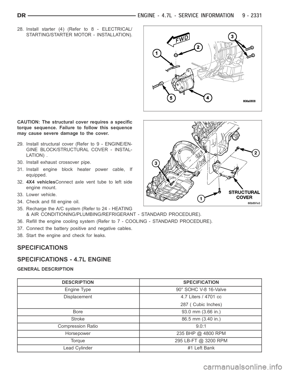
28. Install starter (4) (Refer to 8 - ELECTRICAL/
STARTING/STARTER MOTOR - INSTALLATION).
CAUTION: The structural cover requires a specific
torque sequence. Failure to follow this sequence
may cause severe damage to the cover.
29. Install structural cover (Refer to 9 - ENGINE/EN-
GINE BLOCK/STRUCTURAL COVER - INSTAL-
LATION) .
30. Install exhaust crossover pipe.
31. Install engine block heater power cable, If
equipped.
32.4X4 vehiclesConnect axle vent tube to left side
engine mount.
33. Lower vehicle.
34. Check and fill engine oil.
35. Recharge the A/C system (Refer to 24 - HEATING
& AIR CONDITIONING/PLUMBING/REFRIGERANT - STANDARD PROCEDURE).
36. Refill the engine cooling system (Refer to 7 - COOLING - STANDARD PROCEDURE).
37. Connect the battery positive and negative cables.
38. Start the engine and check for leaks.
SPECIFICATIONS
SPECIFICATIONS - 4.7L ENGINE
GENERAL DESCRIPTION
DESCRIPTION SPECIFICATION
Engine Type 90° SOHC V-8 16-Valve
Displacement 4.7 Liters / 4701 cc
287 ( Cubic Inches)
Bore 93.0 mm (3.66 in.)
Stroke 86.5 mm (3.40 in.)
Compression Ratio 9.0:1
Horsepower 235 BHP @ 4800 RPM
Torque 295 LB-FT @ 3200 RPM
Lead Cylinder #1 Left Bank
Page 1653 of 5267
CYLINDER HEAD
DESCRIPTION
DESCRIPTION - CYLINDER HEAD
The cylinder heads are made of an aluminum alloy. The cylinder head features two valves per cylinder with pressed
in powdered metal valve guides. The cylinder heads also provide enclosures for the timing chain drain, necessitating
unique left and right cylinder heads.
DESCRIPTION - VALVE GUIDES
The valve guides are made of powered metal and are pressed into the cylinderhead. The guides are not replace-
able or serviceable, and valve guide reaming is not recommended. If the guides are worn beyond acceptable limits,
replace the cylinder heads.
DIAGNOSIS AND TESTING
CYLINDER HEAD GASKET
A cylinder head gasket leak can be located between adjacent cylinders or between a cylinder and the adjacent
water jacket.
Possible indications of the cylinder head gasket leaking between adjacent cylinders are:
Loss of engine power
Engine misfiring
Poor fuel economy
Possible indications of the cylinder head gasket leaking between a cylinder and an adjacent water jacket are:
Engine overheating
Loss of coolant
Excessive steam (white smoke) emitting from exhaust
Coolant foaming
CYLINDER-TO-CYLINDER LEAKAGE TEST
To determine if an engine cylinder head gasket is leaking between adjacentcylinders, follow the procedures in Cyl-
inder Compression Pressure Test (Refer to 9 - ENGINE - DIAGNOSIS AND TESTING). An engine cylinder head
gasket leaking between adjacent cylinders will result in approximately a50 - 70% reduction in compression pres-
sure.
CYLINDER-TO-WATER JACKET LEAKAGE TEST
WARNING: USE EXTREME CAUTION WHEN THE ENGINE IS OPERATING WITH COOLANT PRESSURE CAP
REMOVED.
VISUAL TEST METHOD
With the engine cool, remove the coolant pressure cap. Start the engine andallow it to warm up until thermostat
opens.
If a large combustion/compression pressure leak exists, bubbles will be visible in the coolant.
COOLING SYSTEM TESTER METHOD
WARNING: WITH COOLING SYSTEM TESTER IN PLACE, PRESSURE WILL BUILD UP FAST.EXCESSIVE
PRESSURE BUILT UP, BY CONTINUOUS ENGINE OPERATION, MUST BE RELEASED TO A SAFE PRESSURE
POINT. NEVER PERMIT PRESSURE TO EXCEED 138 kPa (20 psi).
Page 1756 of 5267
page page
ENGINE - 5.7L - SERVICE INFORMATION
DESCRIPTION ............................. 2449
DIAGNOSIS AND TESTING
DIAGNOSIS AND TESTING - ENGINE
DIAGNOSIS - INTRODUCTION............. 2449
DIAGNOSIS AND TESTING - ENGINE
DIAGNOSIS - PERFORMANCE............. 2449
DIAGNOSIS AND TESTING - ENGINE
DIAGNOSIS - MECHANICAL............... 2451
DIAGNOSIS AND TESTING - CYLINDER
COMPRESSION PRESSURE............... 2451
DIAGNOSIS AND TESTING - CYLINDER
COMBUSTION PRESSURE LEAKAGE...... 2452
DIAGNOSIS AND TESTING - ENGINE
DIAGNOSIS - LUBRICATION............... 2453
DIAGNOSIS AND TESTING - ENGINE
DIAGNOSIS - MECHANICAL............... 2453
STANDARD PROCEDURE
STANDARD PROCEDURE - REPAIR
DAMAGED OR WORN THREADS.......... 2456
STANDARD PROCEDURE—HYDROSTATIC
LOCK.................................... 2456
REMOVAL ................................. 2457
INSTALLATION ............................. 2462
SPECIFICATIONS
5.7L ENGINE ............................. 2467
TORQUE ................................. 2472
SPECIAL TOOLS
5.7L ENGINE ............................. 2475
ELEMENT - AIR CLEANER
REMOVAL ................................. 2478
INSTALLATION ............................. 2479
CYLINDER HEAD
OPERATION—CYLINDER HEAD ............. 2481
DIAGNOSIS AND TESTING—CYLINDER HEAD
GASKET FAILURE........................ 2481
REMOVAL ................................. 2482
CLEANING ................................. 2484
INSPECTION ............................... 2484
INSTALLATION ............................. 2485
COVER - CYLINDER HEAD
REMOVAL ................................. 2490
INSTALLATION ............................. 2493
VALVES & SEATS - INTAKE/EXHAUST
DESCRIPTION
DESCRIPTION - VALVE GUIDES ........... 2496
DESCRIPTION ........................... 2496
STANDARD PROCEDURE - REFACING ....... 2496
REMOVAL ................................. 2497
INSTALLATION ............................. 2497ROCKER ARM
REMOVAL ................................. 2498
INSTALLATION ............................. 2500
SEALS - VALVE GUIDE
DESCRIPTION ............................. 2503
SPRINGS - VALVE
REMOVAL ................................. 2504
INSTALLATION ............................. 2510
ENGINE BLOCK
CLEANING ................................. 2515
INSPECTION............................... 2515
CAMSHAFT
REMOVAL
REMOVAL - CAMSHAFT CORE HOLE PLUG . 2516
REMOVAL - CAMSHAFT ................... 2516
INSPECTION............................... 2520
INSTALLATION
INSTALLATION - CAMSHAFT CORE HOLE
PLUG.................................... 2520
INSTALLATION - CAMSHAFT .............. 2521
CRANKSHAFT
REMOVAL ................................. 2527
INSTALLATION ............................. 2531
BEARINGS - CRANKSHAFT MAIN
STANDARD PROCEDURE - CRANKSHAFT
MAIN BEARING - FITTING ................. 2536
INSPECTION............................... 2536
SEAL - CRANKSHAFT OIL - FRONT
REMOVAL ................................. 2537
INSTALLATION ............................. 2538
SEAL - CRANKSHAFT OIL - REAR
DIAGNOSIS AND TESTING - REAR SEAL
AREA LEAKS . ............................ 2539
REMOVAL ................................. 2539
INSTALLATION ............................. 2540
RETAINER - CRANK REAR OIL - SEAL
REMOVAL ................................. 2541
INSTALLATION ............................. 2541
FLEX PLATE
REMOVAL ................................. 2542
INSTALLATION ............................. 2542
TAPPETS - HYDRAULIC ROLLER
DIAGNOSIS AND TESTING - HYDRAULIC
TAPPETS ................................ 2543
REMOVAL ................................. 2543
INSTALLATION ............................. 2544
PISTON & CONNECTING ROD
DESCRIPTION ............................. 2546
STANDARD PROCEDURE - PISTON FITTING . 2546
REMOVAL ................................. 2547
CLEANING ................................. 2548
Page 1759 of 5267
CONDITION POSSIBLE CAUSE CORRECTION
ENGINE STALLS OR ROUGH IDLE 1. Idle speed set to low. 1. (Refer to 14 - FUEL SYSTEM/
FUEL INJECTION/IDLE AIR
CONTROL MOTOR - REMOVAL).
2. Idle mixture too lean or too rich. 2. Refer to Powertrain Diagnosis
Information.
3. Vacuum leak. 3. Inspect intake manifold and
vacuum hoses, repair or replace as
necessary.
4. Faulty coil. 4. (Refer to 8 - ELECTRICAL/
IGNITION CONTROL/IGNITION
COIL - REMOVAL).
5. Incorrect engine timing. 5. (Refer to 9 - ENGINE/VALVE
TIMING - STANDARD
PROCEDURE).
ENGINE LOSS OF POWER 1. Dirty or incorrectly gapped spark
plugs.1. (Refer to 8 - ELECTRICAL/
IGNITION CONTROL/SPARK PLUG
- CLEANING).
2. Dirt or water in fuel system. 2. Clean system and replace fuel
filter.
3. Faulty fuel pump. 3. Refer to the Appropriate
Diagnostic Information
4. Blown cylinder head gasket. 4. Replace cylinder head gasket.
5. Low compression. 5. (Refer to 9 - ENGINE -
DIAGNOSIS AND TESTING).
6. Burned, warped or pitted valves. 6. Replace as necessary.
7. Plugged or restricted exhaust
system.7. Inspect and replace as
necessary.
8. Faulty coil. 8. (Refer to 8 - ELECTRICAL/
IGNITION CONTROL/IGNITION
COIL - REMOVAL).
ENGINE MISSES ON
ACCELERATION1. Spark plugs dirty or incorrectly
gapped.1. (Refer to 8 - ELECTRICAL/
IGNITION CONTROL/SPARK PLUG
- CLEANING).
2. Dirt in fuel system. 2. Clean fuel system.
3. Burned, warped or pitted valves. 3. Replcae as necessary.
4. Faulty coil. 4. (Refer to 8 - ELECTRICAL/
IGNITION CONTROL/IGNITION
COIL - REMOVAL).
ENGINE MISSES AT HIGH SPEED 1. Spark plugs dirty or incorrectly
gapped.1. (Refer to 8 - ELECTRICAL/
IGNITION CONTROL/SPARK PLUG
- CLEANING).
2. Faulty coil. 2. (Refer to 8 - ELECTRICAL/
IGNITION CONTROL/IGNITION
COIL - REMOVAL).
3. Dirt or water in fuel system. 3. Clean system and replace fuel
filter.