Page 542 of 5267
P0202-INJECTOR #2 CONTROL CIRCUIT
For a complete wiring diagramRefer to Section 8W.
Page 546 of 5267
P0203-INJECTOR #3 CONTROL CIRCUIT
For a complete wiring diagramRefer to Section 8W.
Page 550 of 5267
P0204-INJECTOR #4 CONTROL CIRCUIT
For a complete wiring diagramRefer to Section 8W.
Page 554 of 5267
P0205-INJECTOR #5 CONTROL CIRCUIT
For a complete wiring diagramRefer to Section 8W.
Page 558 of 5267
P0206-INJECTOR #6 CONTROL CIRCUIT
For a complete wiring diagramRefer to Section 8W.
Page 563 of 5267

For a complete wiring diagramRefer to Section 8W.
When Monitored:
While the engine is running. .
Set Condition:
The engine coolant temperature is above a calibrated value for a calibratedamountoftime.
Possible Causes
ECT SENSOR
OTHER DTC’S
MECHANICAL FAILURE
Always perform the Pre-Diagnostic Troubleshooting procedure before proceeding. (Refer to 9 - ENGINE -
DIAGNOSIS AND TESTING)
Diagnostic Test
1.OTHER DTC’S
With the scan tool, read DTCs.
Are other Cooling system DTC’s present?
Ye s>>
Trouble shoot the other DTC’s first.
Perform POWERTRAIN VERIFICATION TEST VER - 1 (DIESEL). (Refer to 8 - ELECTRICAL/ELEC-
TRONIC CONTROL MODULES/ENGINE CONTROL MODULE - DIAGNOSIS AND TESTING)
No>>
Go To 2
2.ECT SENSOR
Allow the engine to reach normal operating temperature.
Use a temperature probe and measure the engine temperature near the ECT Sensor.
With the scan tool, read the Engine Temperature.
Compare the temperature probe reading with the scan tool reading.
Are the readings within 10° of each other?
Ye s>>
Repair the cause of mechanical failure.
Perform POWERTRAIN VERIFICATION TEST VER - 1 (DIESEL). (Refer to 8 - ELECTRICAL/ELEC-
TRONIC CONTROL MODULES/ENGINE CONTROL MODULE - DIAGNOSIS AND TESTING)
No>>
Replace the coolant temp sensor.
Perform POWERTRAIN VERIFICATION TEST VER - 1 (DIESEL). (Refer to 8 - ELECTRICAL/ELEC-
TRONIC CONTROL MODULES/ENGINE CONTROL MODULE - DIAGNOSIS AND TESTING)
Page 564 of 5267
P0219-CRANKSHAFT POSITION SENSOR OVER SPEED SIGNAL
For a complete wiring diagramRefer to Section 8W.
Page 566 of 5267

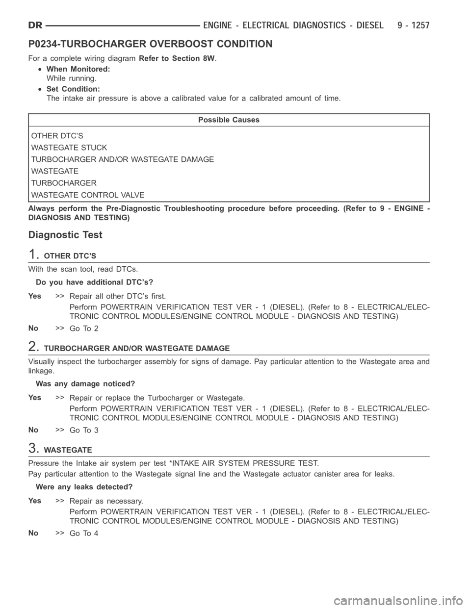
P0234-TURBOCHARGER OVERBOOST CONDITION
For a complete wiring diagramRefer to Section 8W.
When Monitored:
While running.
Set Condition:
The intake air pressure is above a calibrated value for a calibrated amountof time.
Possible Causes
OTHER DTC’S
WASTEGATE STUCK
TURBOCHARGER AND/OR WASTEGATE DAMAGE
WASTEGATE
TURBOCHARGER
WASTEGATE CONTROL VALVE
Always perform the Pre-Diagnostic Troubleshooting procedure before proceeding. (Refer to 9 - ENGINE -
DIAGNOSIS AND TESTING)
Diagnostic Test
1.OTHER DTC’S
With the scan tool, read DTCs.
Do you have additional DTC’s?
Ye s>>
Repair all other DTC’s first.
Perform POWERTRAIN VERIFICATION TEST VER - 1 (DIESEL). (Refer to 8 - ELECTRICAL/ELEC-
TRONIC CONTROL MODULES/ENGINE CONTROL MODULE - DIAGNOSIS AND TESTING)
No>>
Go To 2
2.TURBOCHARGER AND/OR WASTEGATE DAMAGE
Visually inspect the turbocharger assembly for signs of damage. Pay particular attention to the Wastegate area and
linkage.
Was any damage noticed?
Ye s>>
Repair or replace the Turbocharger or Wastegate.
Perform POWERTRAIN VERIFICATION TEST VER - 1 (DIESEL). (Refer to 8 - ELECTRICAL/ELEC-
TRONIC CONTROL MODULES/ENGINE CONTROL MODULE - DIAGNOSIS AND TESTING)
No>>
Go To 3
3.WASTEGATE
Pressure the Intake air system per test *INTAKE AIR SYSTEM PRESSURE TEST.
Pay particular attention to the Wastegate signal line and the Wastegate actuator canister area for leaks.
Were any leaks detected?
Ye s>>
Repair as necessary.
Perform POWERTRAIN VERIFICATION TEST VER - 1 (DIESEL). (Refer to 8 - ELECTRICAL/ELEC-
TRONIC CONTROL MODULES/ENGINE CONTROL MODULE - DIAGNOSIS AND TESTING)
No>>
Go To 4